|
|
Post by angelodp on Jun 13, 2009 20:54:15 GMT -5
Ok I have another body... don't ask!! Its a strat body and I want to do something funky with parts I have.... so, first off, I have an epiphone pickup HB 14.5k .... its has only wire coming out of the armature, that is one outer cover and a ground wire, braided, and a hot black wire. I hesitate to open this up but.... I would like to use this at the neck of my next build and be able to tap one coil or go full HB. Question is, will it be possible to re-wire this pup so that all the inner connecting wires are available for the build?? Its wax potted. 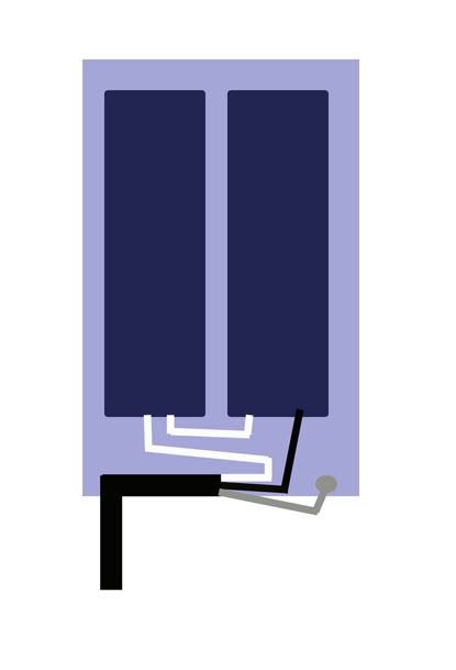 ange PS I can post a pic as well |
|
|
|
Post by JohnH on Jun 13, 2009 21:35:04 GMT -5
|
|
|
|
Post by wolf on Jun 13, 2009 22:01:32 GMT -5
John HGood site and nice graphics. To expand upon what John H already said, yes, it is possible to rewire a 2 wire humbucker into a 4 wire if the humbucker is not one of those chrome-covered, epoxy-filled, sealed for eternity "bricks". And if you'd like a second opinion, here's the information on my website: www.1728.com/guitar1a.htm And, if you're wondering if I have done this, yes I have.
|
|
|
|
Post by angelodp on Jun 13, 2009 22:01:46 GMT -5
There is no case on this pup. Is it best to use the 4 wire method here + ground wire for the armature. So can this mod to this pup be achieved by breaking the jumper and adding two wires?? 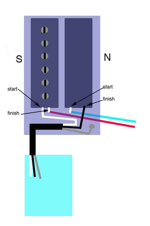 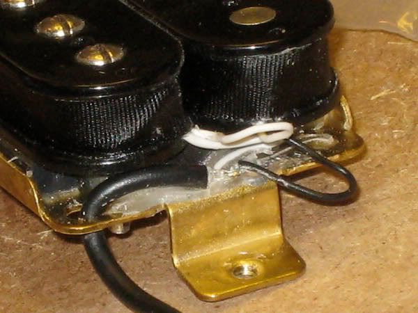 |
|
|
|
Post by wolf on Jun 13, 2009 22:38:27 GMT -5
Hello Angelo, Well, you've been busy posting those graphics. Okay, here's one of my graphics:  I reduced the size of the graphic that was posted originally and then rotated it. I'm not exactly sure about the "start" "finish" positions, but I do know if you cut that center connecting wire, and connect the wires as shown, it will be hooked up correctly. |
|
|
|
Post by angelodp on Jun 13, 2009 22:51:19 GMT -5
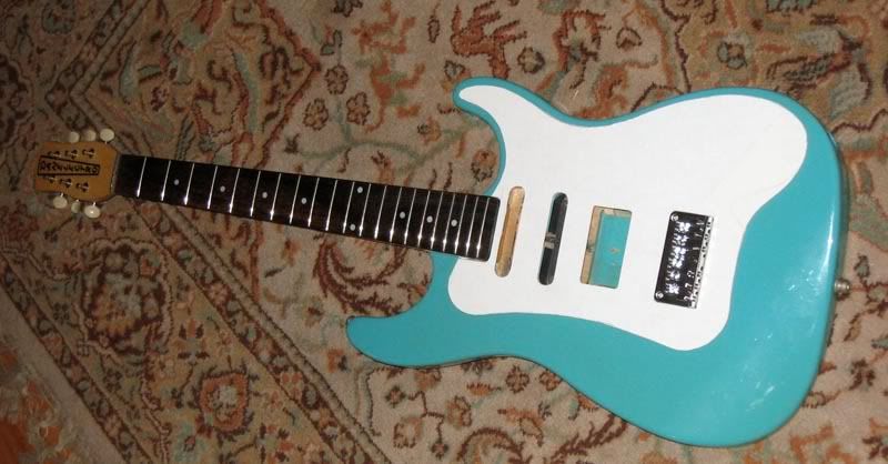
Thanks wolf, ok easy enough. I was trying to avoid cutting off the existing wire and just adding the two leads. I suppose its more tidy to have the four conductor w/ shield to work with. Here is where I am heading with this. i will also be installing tow lipstick pickups on this rig. i am aiming for Master tone & Volume, Split coil on the HB, Standard 5 way settings, various series connections as well as all three ( four ) in series. I have a hardwood plate that will be covered with a custom pick-guard at some point. i wanted to make this reversible so that at some point I may swap necks and go for a vibrato bridge. best Ange 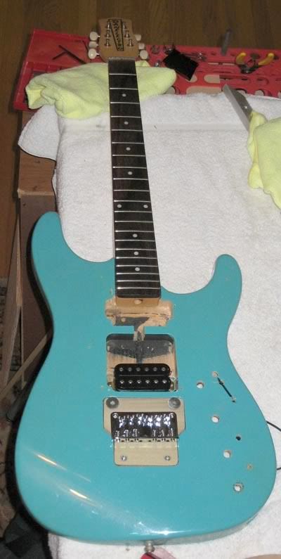 best ange |
|
|
|
Post by sumgai on Jun 13, 2009 23:31:57 GMT -5
ange, That stuff is what we call RTV - Room Temperature Vulcanizing compound. It can be safely peeled off, exposing all your wiring. (Just don't slip, and cut into the coils!) At that point, you can cut both the white and black leads short, cut the jumper (in equal parts), and then secure a new 4-conductor (plus braided shield) to the pickup frame. Using new RTV is OK, if a bit messy. Most folks don't bother, they just tie a knot in the cabling and let go at that. Solder each of the connections using the Western Union splice method, and finish them off with a bit of heat shrink tubing. Use enough heat to fasten the braided shield to the frame quickly, so as not to have heat building up over time, and flowing into the bobbins themselves. This is one case where the older style Weller Gun is a better tool for the job, although most 40 watt irons can get it done, but I'm still leery of the time versus heat flow factor when using any iron - a gun is so much quicker. Finally, be sure to allow yourself plenty of wire length!! No matter how many times you trim a wire, it'll still be too short!   When that's all done, you should double-check your work, and write down your wiring color scheme..... in a safe place - it's embarrassing to forget your own work, and even more so when you didn't make (and keep) a backup.  HTH sumgai |
|
|
|
Post by angelodp on Jun 13, 2009 23:54:45 GMT -5
sumgai, why not avoid the whole business of re-soldering to the frame and the two additional solders to the leads, when simply cutting the jumper and soldering two leads to that is all that is needed. As this is an exposed HB with no cover, I can run the two wires into a jacket and sister them to the already existing wire jacket.... or am I NUTZ!!
ange
|
|
|
|
Post by sumgai on Jun 14, 2009 11:46:42 GMT -5
ange,
You could do that. I was going for the "clean" part of doing the job right, but electrically, your way would work just as well, and be quicker for that.
And yes, as a matter of fact, you are NUTZ! ;D
sumgai
|
|
|
|
Post by angelodp on Jun 14, 2009 12:41:10 GMT -5
Oh good!!!
;D
|
|
|
|
Post by angelodp on Jun 14, 2009 17:01:20 GMT -5
Hi, I have converted the color scheme so that its Seymour Duncan colors, that way i can sk questions that make sense. In the original two wire scheme ( as it come from epiphone ) is this HB wired in series or parallel. In other words what is the standard for wiring with a two wire HB ( + shield wire ). I trust my Seymour Duncan color codes are ok. Oops they were wrong and now corrected. I see on some posts where I can do the HB as series/coilcut/parallel with a DPDT on/on/on switch .... is that right. 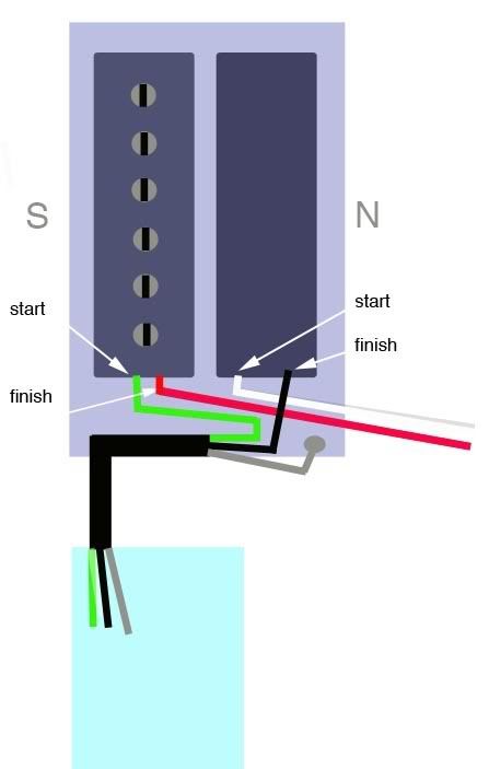 |
|
|
|
Post by newey on Jun 14, 2009 18:03:24 GMT -5
In series, as is standard for HBs. Yes. Our Man Wolf, as usual, is on the job on this one. But you must page back a bit from the diagram to read his discussion of the 2 types of DPDT on-on-on switches. You need to know which type you have. www.1728.com/guitar.htm |
|
|
|
Post by ChrisK on Jun 14, 2009 21:24:33 GMT -5
Before we get carried away here, remember that this circuit does series/single coil/parallel, in this order.
On Wolf's site there is mention of two types of DPDT switches; type "C" which is a DP3T Center-ON (which would be a dual LP-type three-position pickup selector giving one/both/the other) and type "D" which is the regular plain old DP3T Center-ON (ON-ON-ON) switch.
While I am quite familiar with type "D", I have never seen an example of type "C". I have seen DP3T Center-OFF switches everywhere a'planet.
|
|
|
|
Post by angelodp on Jun 15, 2009 7:03:35 GMT -5
Start & Finish versus + & - plus and minus
I have a bit of confusion regarding the use of these conventions with pup nomenclature. I can make more sense of the flow and connection if the start finish approach is used, then I know the actual physical flow. So in wolf's diagram for the switch to use in series/coil-cut/parallel ( Sey Duncan ) he uses + and - for various wires, but it seems to be contrary to the start finish approach. Green is marked as - and this is the start of the coil and as I understand it should be the hot leg of the coil. Should it be + ? I can see that on wolf's site that he is using - for the start convention ... why is that ?
I though hot would be associated with + as in the start of the coil. I understand that the slug coil is rwrp and so the + - flips ...... I just want to be clear on why the green wire ( start of the coil, sey duncan colors ), gets a minus instead of a positive.
Green ( South - Start ) + Red ( South - finish ) - screw coil
Black ( North - Start ) - White ( North - Finish ) + slug coil rwrp
Or does this all go back to Franklin getting the positive negative thing reversed with regard to electron charge?
|
|
|
|
Post by angelodp on Jun 15, 2009 14:02:22 GMT -5
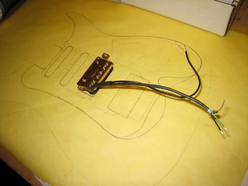
I have decide on this approach for this guitar, and its an open ended experiment for now as I have these pickups and can swap later. I am curious to hear the combos from these disparate types of pickups. I suppose its obvious as to what i am going for here but just in case. The dano pickups have red and white wires and a cover ground. I am told that the rwrp 6k still has the wires as red/ hot and white ground just like the 5k. I simply want to have a coil cut and series parallel function with the HB and also be able to throw the Neck pup on for all three combos as well as the others that would be achieved on the 5 way. Question is - have i got this wiring correct. ange 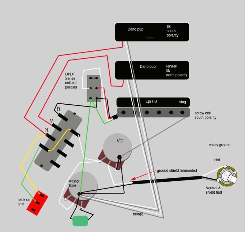 |
|
|
|
Post by ChrisK on Jun 15, 2009 14:26:23 GMT -5
Maybe Wolf didn't use the Duncan color code. No, it's AC my dear Watson, and all relative. A Dissertation on PickupsFirst and foremost, pickups do not have an output signal polarity, since they generate an AC signal, they have phase, which is relative to something else. There are three components to the phase of a pickup output signal; 1. The direction of movement of the string within the magnetic field, usually toward and away from the poles. Side to side movement generates little signal (the magnetic field is the same). The movement is the same over every pickup at the fundamental frequency. It is not the same at the harmonics.  2. The polarity (polarization) of the magnet(s). 3. The direction of winding. This is trivially reversed by reversing the two leads connections to the external circuit. There are those that claim that this is not so, and that there is "something" more to it. I can't see this and no one has been able to offer a rational explanation thereof (as in engineering terms and not just complete sentences), so it remains "fairy dust". Now, if a pickup has one lead grounded, and that lead goes to the layers of windings that are on the outside perimeter of the coil, there will be some shielding effect to this. This is similar to the "outside foil" marking and use on capacitors. Second, keep in mind that pickups do not have "hot" and "ground" leads, but just signal leads that may be subsequently connected to the output or ground (or anywhere else that some nuts might want to connect them). This is slightly complicated, requires folk to understand how things actually work, and is relative only the other pickups, so conventions are used. If the "start" lead (assuming that the winding direction CW or CCW is consistent between all pickups discussed) is connected to the instrument output, the "finish' lead is connected to the instrument ground, and all magnets in all coils have the same polarity (N or S), then the output signals will all be in AC phase with each other. We mark these leads with a "+" or a "-" since these are accurate indications of the instantaneous output voltages at some point in time at the end of a completely undefined period time. We could specify the string position, the winding direction, and the magnet polarity, but the output voltage is proportional to the rate of string position change (velocity) and NOT to the displacement of the string (position). So, we use the "+" and "-" conventions to indicate that, with all things being the same, the relative phase of the output signals will be similar "+" or opposite "-". Ergo (or egads depending on one's "vision"), for a hum-canceling effect to occur between two coils, one of them will have to be wound the opposite direction with respect to the other. We will call that one RW even though both are out of phase with each other (convention is). Since we have reversed the phase of the winding, to keep its output signal in phase with the other coil, we have to reverse its magnetic polarity and call it RP. RWRP means Reverse Wound, Reversed (magnet) Polarity. So for the sake of convention, a "start" lead on one coil with one magnet polarity will be the "hot" output (only because we conventionally call it so "+"), the "finish" lead on the same coil ("-") will be connected to the "finish" lead on the second coil ("+") with the opposite magnet polarity, and the 'start' lead of the second coil ("-") will be connected to 'ground". All things will be in-phase signal-wise and out-of-phase noise-wise. "Start' and "finish" do not indicate the polarity of the output. They indicate the relative winding direction of the coil. This, in conjunction with the magnet polarity and the direction of string movement through the magnetic field determine the relative phase of the output signal. If you rewired a guitar such that all of the coil's two leads were reversed (ignoring the issue with single conductor with shield), the guitar would work exactly the same. If all magnets were reversed, the guitar would work exactly the same. If all of the coil's two leads were reversed and all magnets were reversed, the guitar would work exactly the same. See, it's all relatively simple. And, speaking of relative, we don't know what the winding direction was, nor what the two wires were connected to anyway. At least one can see if the magnets attract between two pickup coils; if they do, the two coils are RP and, as long as no pickup leads are prematurely grounded, The RW part is simple. |
|
|
|
Post by angelodp on Jun 15, 2009 15:10:09 GMT -5
Ok, ah sooooo..... and so how does my little layout look..... is it a green light or gefoooey?
ange
|
|
|
|
Post by D2o on Jun 15, 2009 16:07:07 GMT -5
hmmm ... now which magnets do you mean - the flat one on the bottom or the 6 pole pieces? A week or so ago I asked the question (here) of whether the magnet would have to be rotated when a pickup is installed "backwards" (i.e. spun 180 degrees, so that the front faces the back). I was told that the magnet's polarity is top to bottom and spinning it 180 degrees causes no issues with respect to polarity. Now, I meant the flat magnet on the bottom and I was not sure if the responses I got were referring to the same magnet or if they were referring to the 6 pole pieces, but - if the polarity is top to bottom - why mention the magnets? Unless the polarity is not top to bottom? Can you please elucijudicate? D2o |
|
|
|
Post by ChrisK on Jun 15, 2009 16:19:45 GMT -5
ange,
Aside from the wiring of the Epi pickup, the rest of your wiring looks ok from a quick look. The Epi pickup viewed on my laptop screen seems to have a black wire and a slightly less black wire (but this is a guess).
I wrote the info on pickups since I cannot tell whether the Epi will be in-phase or out-of-phase with the other two pickups, and I wanted to state the theory of operation so that all can derive things.
Looking at the Epi and trying to reconstruct its path to date; I perceive the following;
The left wire to the south screw coil was white.
The right wire from the south screw coil to
the left wire to the north slug coil was a white jumper.
The right wire to the north slug coil was black.
Now,
The left (?start) wire to the south screw coil is green.
The right (?finish) wire from the south screw coil is red.
The left (?finish) wire to the north slug coil is black.
The right (?start) wire to the north slug coil was white.
When in series mode, the red and black wires are connected together. When in parallel mode, the green and black wires are connected together, and the red and white wires are connected together.
|
|
|
|
Post by wolf on Jun 15, 2009 16:22:58 GMT -5
Wow, I stay away for a day or two and there's lots of stuff going on here. As most of you know, I never talk about a pickup's "start" or "finish" or whether the magnet is "north" or "south" polarity. As a matter of fact, here's someone else who agrees with me: www.neighborhost.com/scrapbook/pickup-id.htmlYes, I just use those '+' and '-' signs because it is a lot simpler than saying "connect the 'finish' of the 'south' polarity coil ..." And ChrisK, I was surprised too that I could not find a DPDT center on switch that works like Diagram 'C'. Perhaps it is a difference in our ages. (I'm 57 - a rather advanced age for an electric guitar player). I know that they used to make those. Guess I'll have to pay a visit to the Edison Electric Company and see if they have any. ;D |
|
|
|
Post by ChrisK on Jun 15, 2009 16:40:02 GMT -5
I wasn't surprised, too.  That's likely the reason, after all I was born in 1952, so I have the advantage. (I don't.)  |
|
|
|
Post by angelodp on Jun 15, 2009 17:07:21 GMT -5
damn, I just realized that I screwed up on the SD color coding, the black and white wires should be reversed, that will affect my other diagram. I will make the changes.
|
|
|
|
Post by ChrisK on Jun 15, 2009 17:39:47 GMT -5
This seems clear enough. The output phase of all signals would be reversed, but it's AC so all is still relative and hence, the same. Reversed, as in reversed by interchanging all north poles with all south poles and conversely. Not rotated about their axis of magnetization. Ergo! Or do you mean the single coil pickups with flat magnet on the bottom and the 6 pole pieces? I reread this a number of times and cannot figure out what you're saying. Especially about the clock with the magnet on the bottom.  The magnet under a coil predominantly presents a single magnetic polarity through each coil. If a magnet is rotated about its axis of magnetization (which would be the center of the cylinder that is a Fender single coil slug magnet), everything is the same. If the single coil Fender-style pickup is rotated about its pole piece's axis of magnetization, the coil winding phase remains the same and the magnetic polarity remains the same, so everything is the same. What I believe that you mean(t) is the flat bar magnet located on the bottom of a pickup type that is occasionally referred to as a humbucker, or more properly, a side-by-side coil humbucker. This type of pickup usually has ferrous material extending through each coil in the form of screws, slugs, or blades. The resulting structure is similar to side-by-side single coil pickups, with the exception of differing magnetic polarities and field structure. Since rotating a side-by-side coil humbucker results in the coil winding phases remaining the same, and the magnetic polarity through each coil remains the same, everything is the same. However'ski, if you rotate the flat bar magnet under a side-by-side coil humbucker such that the opposite magnetic polarity is now predominantly presented through each coil, the output signal will be of the opposite phase compared to what it was. There are the three things that contribute to a pickups output phase; if you change an odd number of them (1 or 3), the output phase is reversed. If you change an even number of them (0 or 2), things remain the same. This is relative to another pickup. If you change any set of things on every pickup, things are the same. If you change any set of things on a subset of all pickups, you may (oddly) or may not (evenly) change phasing. Can you actually use elucijudicate in a sentence? |
|
|
|
Post by angelodp on Jun 15, 2009 17:50:30 GMT -5
Wolf, that was a great site and now I understand why you are using the + and - nomenclature. I followed the sites test procedure and now have a translation of my pickup colors for the SD colors and can proceed. I am still trying to deal with the 4 conductor wire as I do not have any at the moment. I tried to make one by pulling out a shielded pair that has foil and a drain-wire form a multi conductor wire i have and then putting a piece of shrink tube over the whole deal. I cannot quite get that additional wire threw the existing armature hole so that I can sister that shielded wire to the other. This will require that the extra shield is also soldered to the armature and then to ground on the other end.... workin on it.
ange
|
|
|
|
Post by ChrisK on Jun 15, 2009 17:52:58 GMT -5
See! Oh, my bad, I meant a'ha, glad to help! This link that wolf posted is a really good procedure to follow. I like the ordered approach to it. It should be done for all pickups and kept in a logbook. Artie's Guitar ScrapbookYou end up with working info, you can record the magnet polarity as (it does come in handy), and you can stick the start/finish stuff in some other wazoo. Speaking of magnet polarity; have you given thought to which coil will be in use with the middle pickup (for hum cancellation)? |
|
|
|
Post by angelodp on Jun 15, 2009 19:23:52 GMT -5
Yes, the neck pickup should work and the bridge pickup in coil cut should work. At least I hope so. I believe that the single coil on the HB is the same wind and polarity as the Neck and the middle is the rwrp. Unless you see something I am missing.
thanks ange
|
|
|
|
Post by angelodp on Jun 15, 2009 23:41:38 GMT -5
|
|
|
|
Post by angelodp on Jun 16, 2009 0:46:53 GMT -5
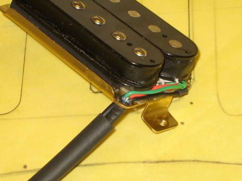
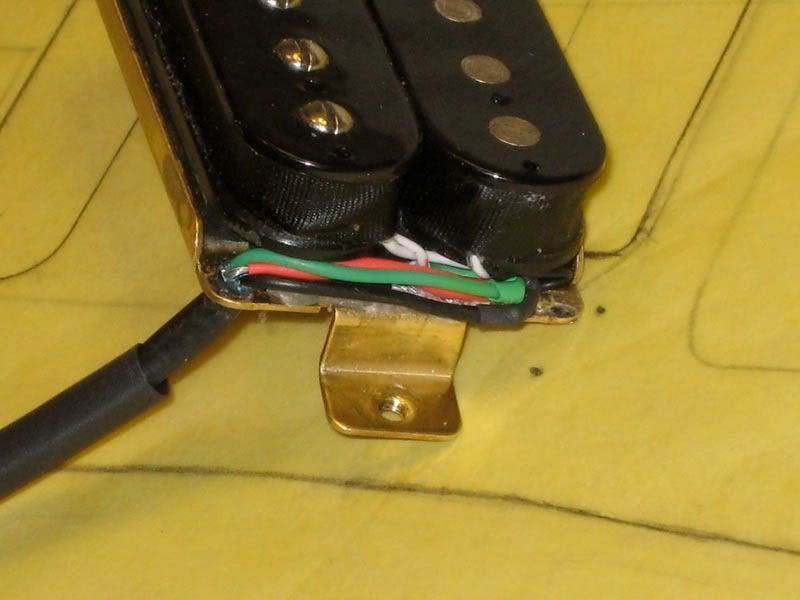
Oh well, you live and learn, should woulda coulda..... In the original graphic of what my HB was wired like, I failed to clarify that the right hand black wire was actually soldered to the ground ( armature ground ) wire and did not work its way forward in the sleeve as I showed it. See the first graphic for the corrected version. So when I made up the Sey Duncan color code graphic I failed to clarify that point and ended up with that black wire still soldered to the plate ground but showed it incorrectly ..... it should be as in the second drawing. The Grey wire representing the Black wire and the ground still conjoined, and is the braided wire carrying the black wire. In the picture you can see the white jumper and the white hot and the black end of the coil which is soldered to the plate braided wire ( shield ). So the question is can I leave that as is, now that I have the jumper wire cut and a new shielded pair coming out. Essentially the Black/Grey wire can be the ground now to the series/coil-cut/parallel switch ( bottom lug left side ) and the green wire becomes the hot to the switch. I would have to switch the red and white wires on the lipstick pups to maintain phase and rwrp set-up. Does that make sense or do i have to separate the black wire from the plate ground and run that wire out on its own. I know, would have been simpler to do the 4 conductor wire from the start. But here i am and perhaps this is a test of what I have or have not learned in this build. 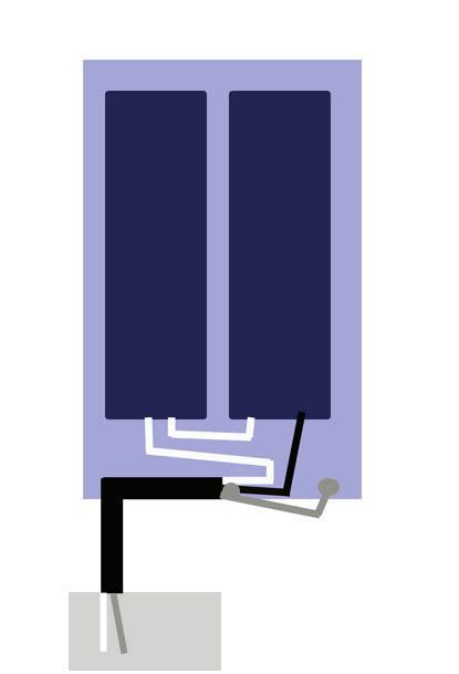 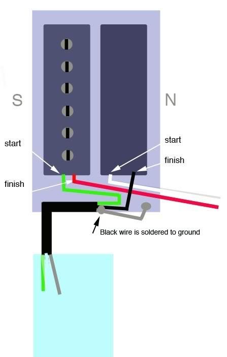 |
|
|
|
Post by ChrisK on Jun 16, 2009 12:14:56 GMT -5
Well, having one wire connected to the system ground at the pickup isn't the end of the world. It does predetermine the coil phasing and hence humbucker pickup phasing. Depending on the phasing of the other pickups with this fixation, you may need to swap the connections into your circuit for the leads coming from them.
I'm not going to try to follow your post, it's making my phase hurt (relatively, that is). ;D ;D
summary
You have one lead to one coil permanently grounded. That sets the phasing for the rest of the guitar.
You can still bring out the other three leads and do the series/single/parallel switching.
You can still do the 5-way lever switching as well. You may have to reverse the lead wiring connections for the middle and neck pickups to correct phasing, but having two wires plus shield enables this easily.
Done is.
/summary
|
|
|
|
Post by ChrisK on Jun 16, 2009 12:23:16 GMT -5
I don't know, I wasn't there as I had a meeting in Boston that week and ended up on my back in a pub with a wenched neck.
Besides, although I've asked him about this, he isn't talking.
Interestingly though, the term "battery" came from his thinking that an array of Leyden jars looked like a battery of artillery (hence a battery of cells/jars).
|
|