chille51
Rookie Solder Flinger

Posts: 16
Likes: 0
|
Post by chille51 on May 15, 2011 22:51:29 GMT -5
Hey all. Just found this site today while doing some research, and figured this would be a good place to post my question. I've searched through the forum, and haven't found this specific scenario. In any event, I've got a LP with two four wire humbuckers, and a couple of push-pull pots for the tone controls. I've never done any of these kinds of mods though, and haven't been able to dig up the diagram for exactly what I have in mind (if it's even possible). Any comments, drawings or links appreciated. The three mods I'd like to integrate are: 1) A spin-a-split for the neck pickup. Basically you sacrifice one tone control (making the other one a master tone), and turn it into a variable coil split. So instead of just being split or not split, you can turn the knob and dial in a varying balance between the coils. www.smitspickups.com/coiltapping.htm About halfway down the page. 2) Use the push/pull on this same knob to put the pickups in either parallel , or series to eachother. www.1728.com/guitar10.htm The second, single switch option 3) Use the other push/pull to put the pickups in our out of phase from one another www.1728.com/guitar.htm near the bottom of the page. I've found links and diagrams for each of these mods individually, just not sure if there is any consideration I'm missing or reasons I can't do all three, as noted above? |
|
|
|
Post by JohnH on May 16, 2011 0:46:53 GMT -5
hello and welcome to GN2. What you suggest is perfectly possible, and those mods can work well together. Id suggest looking at one of the ' Jimmy Page' mods, of which we have several in the schematics section, and use that as a reference. Just omit the switched coil-cuts, and change the tone pots as you suggest. BTW my own favorite LP wiring uses essentially the same switches as you have, being two dpdt switches. Yours are on push/pull pots while I have them as sliders at the back of the switch cavity. It has series/parallel and phase, and coil cut combined with tone control on each tone pot. LP modular wiring design cheers John |
|
|
|
Post by ChristoMephisto on May 16, 2011 8:34:06 GMT -5
The first and second requests sounds like the Series/Parallel Blend Pot w/ DPDT switch. guitarnuts2.proboards.com/index.cgi?board=modules&action=display&thread=3863Some ppl have problems with blend pot due to the taper, and some don't, you may want to go with one of the various JP LP mods instead. You won't hear much of a difference between the two coils on the neck pup also depending if it's in combo with the bridge pup. |
|
chille51
Rookie Solder Flinger
Posts: 16
Likes: 0
|
Post by chille51 on May 16, 2011 10:53:29 GMT -5
Thanks guys,
Christo… I must admit that I’m not that great at reading schematics. Is there a wiring diagram of that one that you’re aware of? What exactly does it do? John… I did look at the JP wiring, but it seems like it might be more than I need. Plus it is well documented, and part of this exercise is for me to learn a little more about guitar wiring. That’s the reason I’ve tried to limit it to two push pulls, and a handful of mods out of all of the options. From what I’ve read, these are the ones that appeal to me the most… and I like the idea of “hacking” a few different schematics together into one circuit myself. Like I said, as much for the learning process as the end result.
Maybe what I’ll do is try writing up my own wiring diagram based on the all of the stuff above, and then post it here for you guys to tell me where I screwed it up and how I can fix it?
Cheers!
|
|
chille51
Rookie Solder Flinger
Posts: 16
Likes: 0
|
Post by chille51 on May 16, 2011 11:00:15 GMT -5
John,
I must admit that I just had a closer look at the link you posted, and it looks pretty close to what I’m trying to achieve. I may borrow from it a fair bit! A couple questions from your description:
1) When you say series/parallel, that is between the two pickups correct? Not between the coils in a single pickup?
2) How do you have coil cut and tone control on the same pot?
Thanks for entertaining a newby. I can read the diagram as far as what is connected to what… but I’m not really experienced enough yet to figure out how it translates into the functionality you describe.
|
|
|
|
Post by JohnH on May 16, 2011 15:29:20 GMT -5
1 - yes, series/parallel is between the two pickups.
2 - it uses the third, outer lug, which is usually disconnected, to go to the central connection between the coils of the pickup. At 10, this point is grounded, so its single coil. At 9 and below, its humbucker, gradually turning down the tone as normal, down to 0. Its not a standard arrangement, but I have come to like it very much and you can set hb/sc mixes between the two pickups. Also, both sc's, then in overall series is a nice tone - so lots of options.
But the setup that you described is also very good, and practical to play
John
|
|
chille51
Rookie Solder Flinger
Posts: 16
Likes: 0
|
Post by chille51 on May 16, 2011 15:59:54 GMT -5
Very cool. So this might be a dumb question, but could you do one spin-a-split, say on the neck tone control, and then do what you've described to split the bridge coils with the other tone control, but still have it act as a master tone control as well? Or am I just getting rediculous now? Basically a hybrid of what I originally said, and your design.
|
|
|
|
Post by JohnH on May 17, 2011 5:16:43 GMT -5
Ok, in principal, yes all that could work. Id suggest planning out your wiring so you can test a few options. All your switching could be settled, but then with a couple of moves on the tone pots you could check out:
two spin-a splits
two tone/splits - as my design
one of each as you describe above
your original suggestion
You might find a preference for one over the others.
How's the overall tone of your guitar, in terms of brightness? If you are always looking for more edge, your brightest option out of all of those is two spin splits, which puts less load on the coils. The most muted tone will be with series mode and a master tone, or same with combined with the coil cut per my version.
My version as posted works pretty well with the medium output Classic 57 pups that I have. i actually tried wiring with spin a splits, on both and it does work well but I found i was also wanted full split or HB but thats just my findings.
John
|
|
chille51
Rookie Solder Flinger
Posts: 16
Likes: 0
|
Post by chille51 on May 17, 2011 14:46:53 GMT -5
Ok... so I did do a very rough sketch up. As it is my first time ever doing a pickup wiring design, I'm sure it is riddled with errors. That's where you guys come in! Please let me know if anything is unclear... I know it is a pretty rough drawing. 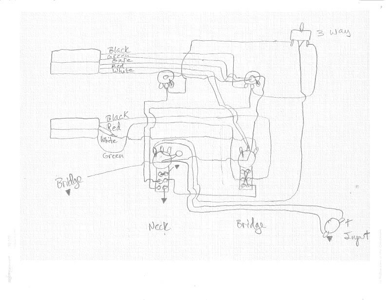 I started with the Seymour Duncan 2 humbuckers, 3 way, 2 volume 1 tone diagram as the base, and attempted to wedge in the following mods from other drawings: 1) Spin a slit on neck tone 2) Tone split (as per JohnH) on bridge tone 3) Phase switch on bridge push/pull 4) Master series/parallel switch on neck push/pull On review just now I see that I took the red/white coil leads for the neck PUP to the wrong tone pot... probably should have just went to bed last night instead of pushing to finish this. Please factore those as connected to the centre lug on the NECK tone control. This is based on Seymour Duncan colors. My actual pickups are GFS, and the colours are the same. Only difference is their wiring diagram shows the North start (black) connected to ground, and the South start (green) connected to hot. SD seems to have it the opposite... but my understanding is since the coils are in series it doesn't really matter which direction the signal flows through them. Please correct me if I'm wrong. That's about it. Thanks for the help so far, and for helping me sort this mess that I've created above out! |
|
chille51
Rookie Solder Flinger
Posts: 16
Likes: 0
|
Post by chille51 on May 17, 2011 14:49:20 GMT -5
Actually... it looks like with all my confusion trying to sort out the phase/series switches, I managed to royally botch the split controls all together... I'll probably just have to redraw this.
|
|
|
|
Post by Yew on May 22, 2011 14:28:50 GMT -5
If you feel like getting another Push/pull pot, here is a way to make your variale coil tap also function as a variable broadbucker.  ust as a note the phase switch is optional, however variable out of phaseness, and out of phase highs through the broadbucker could be an intresting sound |
|
chille51
Rookie Solder Flinger
Posts: 16
Likes: 0
|
Post by chille51 on May 23, 2011 18:39:07 GMT -5
Ok guys... I think I got pretty close this time. Can someone check this for me and make sure I'm not doing anything wrong: Intent is: Two volumes, 1 master tone, 3 way Spin a split on bridge tone JohnH tone split on neck/master tone Series/parallel switch on bridge push pull Phase switch on neck push pull 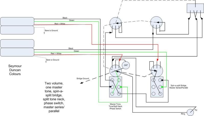 |
|
|
|
Post by newey on May 24, 2011 5:05:47 GMT -5
chille51-
With the phase switch "up" (IOW, connecting the top lugs as shown on the diagram), and with the series/parallel switch set to series (also "up") both pickups get connected to the neck volume pot "hot" lead. This defeats the series connection between the two.
|
|
chille51
Rookie Solder Flinger
Posts: 16
Likes: 0
|
Post by chille51 on May 24, 2011 8:51:42 GMT -5
Thanks Newey! Any suggestions how to fix that? I'll also go back and look at the design I copped the series phase switches from and make sure I haven't missed anything.
|
|
chille51
Rookie Solder Flinger
Posts: 16
Likes: 0
|
Post by chille51 on May 24, 2011 21:39:41 GMT -5
Wow... I really am smashing my head against the wall here. How DO I have both out of phase and series at the same time?
|
|
|
|
Post by newey on May 24, 2011 22:44:15 GMT -5
Take a look at the diagram from JohnH's JP. This is similar to what you're doing, except on the bridge instead of the neck (relabel accordingly . . .), and you don't use a switch to split the coils. But the basic idea is the same- wire the phase switch right after the pickup, then wire in the V and T, then the series/parallel switch after that. Anyway, I think that's the way to do it. Let's get some help from others on this first. |
|
chille51
Rookie Solder Flinger
Posts: 16
Likes: 0
|
Post by chille51 on May 25, 2011 21:14:57 GMT -5
Thanks Newey. I did go and look at JohnH's JP mod, and it did help, as did your description. Still not sure I got it right, but I think I'm headed in the right direction. I don't have Visio on my home PC to alter the drawing (did it at work), but these are the changes I have in mind:
- Delete the connection between lug F on phase switch and lug D on series switch
- Instead of going from centre lug on the neck volume to the 3 way, take that connection to lug D on the series switch instead
- Connect lug D through to 3 way
I think this works... but I'm probably still wrong. Anyone want to verify? It is basically what you said Newey, going from Pickup to phase switch to volume control to series switch to toggle. I think. LOL.
|
|
|
|
Post by newey on May 25, 2011 22:48:45 GMT -5
Well, I've been playing around with this for a couple of hours and I can't seem to get it, either. I'm pretty sure it can be done, I'm just not seeing it.  Lemme stare at it a bit more . . . |
|
chille51
Rookie Solder Flinger
Posts: 16
Likes: 0
|
Post by chille51 on May 26, 2011 10:49:46 GMT -5
Yeah, I’m having a hard time with it myself. Are you sure the connection to the volume pot defeats the series setting? Because I was just thinking about it abstractly, and I’m not sure how you would have a series connection WITHOUT connecting to the volume pot. If the idea of the pickups being in series is that the negative lead on PUP 1 connects to the hot lead on PUP 2, thereby forcing the signal of PUP 1 to travel through PUP 2 before it gets to ground… well presumably that second hot lead is always going to be connected to a volume pot at some point, no? How else would you have volume control?
Maybe I’m missing something fundamental here? Not doubting you Newey, just trying to understand what I might be overlooking in my theory.
|
|
|
|
Post by newey on May 26, 2011 15:23:32 GMT -5
No, you're right to doubt me. I'm doubting myself, that's why I wanted someone else's opinion.
In series, one can (again, AFAIK . . . ) use a master volume pot after the series connection, and right before the output jack. This is how it's usually done.
With individual volume in series, these are problematic since turning one knob down affects both pickups. But if one is going to do it, I've only seen it done where the volume is wired in between the 2 coils, in from one and out to the other.
As I see your diagram, with the pickup selector switch in the center, with the phase switch "up" as stated, and with the S/P switch set to series, it looks like the 2 pickups are connected in both series and parallel at the same time.
Your suggested revision leaves lug "F" of the phase switch unconnected to anything in one position, so I see that as a problem.
But again, I'd like some backup on this as I admit to being unsure.
|
|
|
|
Post by JohnH on May 26, 2011 15:35:03 GMT -5
I think you are on the right lines with neweys post 15, but what's the problem?
J
|
|
|
|
Post by newey on May 26, 2011 18:24:37 GMT -5
Thanks, John!
Well, Question #1 is whether chille51's original diagram will work as intended, or is the series wiring indeed a problem?
My specific problem comes about trying to directly replace the coil split switches with the Spin-A-Split.
I figured that you've got Pickup---Phase switch---Coil split switches----V & T pots------System series/parallel----Pickup selector switch----Output.
Chille wants Pickup----Phase switch----Spin-A-Split---Volume Pot---System Series/Parallel----Pickup Selector switch----Output.
I had drawn something up just directly substituting the Spin-A-Split "module" in place of the Coil Cut switches. But I just can't seem to figure it, I'm pretty convinced that my first attempt is gefooey.
|
|
chille51
Rookie Solder Flinger
Posts: 16
Likes: 0
|
Post by chille51 on May 26, 2011 18:57:10 GMT -5
I guess I have one question that might help me sort it out in my head a bit. I'm not sure which pickup I should be aiming to put first in the series. I've tried to draw it out both ways. In this case, I have the neck pickup being flipped out of phase on the phase switch. Do I then want the neck pickup first in the series, or last? Does it matter? Is one easier to achieve then the other?
|
|
|
|
Post by newey on May 26, 2011 22:23:03 GMT -5
The series order doesn't matter, and it makes no difference what pickup has the phase switch.
|
|
|
|
Post by JohnH on May 27, 2011 17:00:15 GMT -5
I think this schematic sketch is probably what you want:  The bridge gets the spin a split instead of a tone pot, so 0 is fully split and 10 is full Hb. When I tried this I found most of the tone change happens between 0 and about 4, and it is nice to keep a bit of weight in a split bridge humbucker, by setting at about 1 or so. So it's a good option. Each pup gets a volume control, which work to control mixes in both series and parallel modes. They should be 500k log taper, as should the other pots. The master tone VR4 will split the neck when set at 10. S1 is the standard toggle and S3 does series/parallel, overriding the main toggle when in series mode S2 is neck phase and works in all modes, also changing which neck coil is split. I've put SD colours so that if you have two identical SD pups, you get hum cancelling in all modes where both pups are split, in and out of phase. Confirm this by checking if both screw coils have the same magnetic polarity (ie do they repel each other when placed together - or similarly repel the same end of another magnet?) Treble bleed circuits are added to the volume pots, highly recommended but optional. I think all that will work fine, but there are a couple of niggling concerns about the master tone arrangement: 1. Having the master tone after the volume pots will mean that the tone control works differently when the volumes are reduced,since it is then not directly connected to the pickup coils. Its not unknown though, and Explorers are wired this way, so see what you think 2. A master tone across the output, when in series mode, will take the edge off the tone as compared to having it just for one pickup. But I wouldn't worry too much, I think this is well worth a try. But you might like to make provision when wiring, to try changing the master tone to a neck-only tone, still with the neck split function. All you need to do is to move the output end on the tone cap to the top end of the neck volume pot ('10' on VR2 above) cheers John |
|
|
|
Post by newey on May 27, 2011 17:45:20 GMT -5
Thanks, John, that looks good!
So, the Spin-A-Split can just be dropped in there, apparently. I was worried unnecessarily.
Chille51-
If you can't read JohnH's schematic, I can translate it into a diagram for you (halfway done already), but I'm leaving town for Memorial Day and may not get to it until next week.
|
|
chille51
Rookie Solder Flinger
Posts: 16
Likes: 0
|
Post by chille51 on May 30, 2011 15:53:20 GMT -5
Wow, thanks guys. Sorry it took me a while to get back to you, I was out of town this weekend. Thanks for the schematic John! And Newey, thanks for translating it into a wiring diagram if you ever get to it. I'm much better at reading those!
|
|
|
|
Post by newey on May 30, 2011 18:28:31 GMT -5
OK, chille51, but let's have someone else check this before you start wiring it, I'm not totally sure it's right. 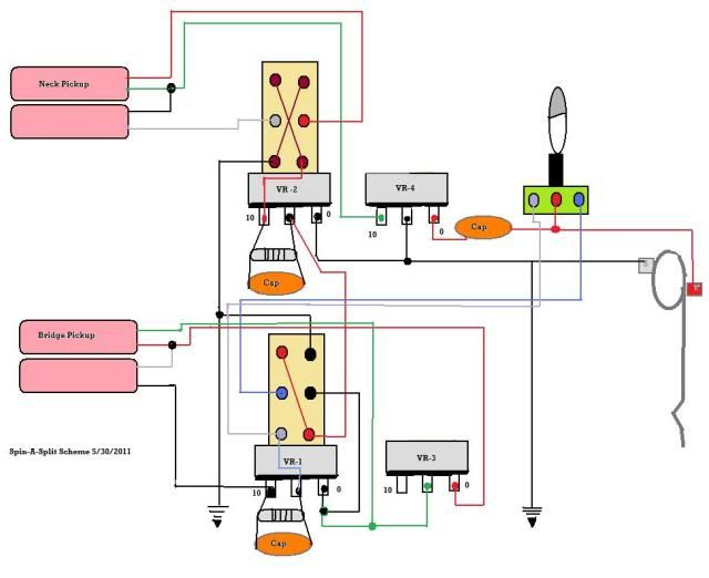 Wires that cross are not connected unless there's a dot. |
|
|
|
Post by JohnH on May 31, 2011 6:34:35 GMT -5
Seems basicly good. Just swap the red and white wires from the neck pickup where they connect to the phase switch, so the switch pushed in is in-phase.
Also, note the the pots are drawn assuming the shafts point downwards on the diagram, and the three main lugs on each pot are nearest the viewer, not on the far side.
cheers
John
|
|
|
|
Post by sumgai on May 31, 2011 16:50:54 GMT -5
newey,
That's a pretty nice diagram there, pardner. Certainly better than what you were doing this time last year! ;D
I'd ask, very politely, that you see if you can make the text a bit larger, but other than that, it's easily as good as anything else posted here in The NutzHouse.
I'm gonna go ask The Real Boss if I can +1 ya, but first I gotta wait 'til he wakes up from his early afternoon catnap.....
sumgai
|
|


