|
|
Post by JohnH on Apr 18, 2024 19:07:36 GMT -5
That on-on-on is a usefully thing! A Gibson-style toggle is good to use, and other than that, most on-on-on's are the mini toggles which are great for tone tweaking but too fiddly for changes while playing.
|
|
gdw3
Rookie Solder Flinger
 [Insert clever comment here]
Posts: 4
Likes: 0
|
Post by gdw3 on Apr 18, 2024 8:11:33 GMT -5
Yogi B Can I ask you kind of a noob question? I'm looking at the switch you linked to. Is the ground connection the small squat terminal in the middle?
|
|
gdw3
Rookie Solder Flinger
[Insert clever comment here]
Posts: 4
Likes: 0
|
Post by gdw3 on Apr 18, 2024 7:56:21 GMT -5
Ah, that's very clever. I'll have to measure the cavity, but it's fairly deep. Thank you Yogi B! |
|
|
|
Post by stevewf on Apr 17, 2024 22:46:23 GMT -5
It needn't be a DP3T, a DPDT ON/ON/ON (such as this) can work too: And thanks for finding that, Yogi B. I've been harboring a couple half-cooked schemes for that switch, and have now ordered two! |
|
|
|
Post by stevewf on Apr 17, 2024 20:10:41 GMT -5
Does the guitar have a cavity large (wide) enough for this switch? It's pretty big. It's a toggle switch meant for a two-neck Gibson-style guitar; it's a three position DPDT. Edit: Ooops, I got it confused with another switch I got a long time ago. This is not a DPDT.
Now I remember. It's this Switchcraft Lever Switch. It's a whopping 4PDT. I's also physically whopping, which is why I haven't used it, not to mention the unconventional knob. There's up to 8PDT version available if your guitar is to be built for taking over the world. Yogi's find looks like the way to go. |
|
|
|
Post by Yogi B on Apr 17, 2024 18:41:27 GMT -5
Also, if you can change to a different type of 3-way such as a Telecaster switch. It needn't be a DP3T, a DPDT ON/ON/ON (such as this) can work too: gdw3, note the switch linked above has 6 terminals (7 including chassis ground), one more than is strictly necessary for Gibson's traditional 3-pickup wiring. Therefore, it's not certain that all toggle switches billed as being for 3-pickup guitars are suitable — something to be aware of. |
|
gdw3
Rookie Solder Flinger
[Insert clever comment here]
Posts: 4
Likes: 0
|
Post by gdw3 on Apr 17, 2024 16:49:36 GMT -5
That's what I figured. I realized it after I opened up the guitar and started looking at the wiring. The whole idea was to simplify things, so adding another switch would be the opposite of that! Thanks.
|
|
|
|
Post by JohnH on Apr 17, 2024 16:04:47 GMT -5
hi gdw3 and welcome to GN2. Most probably the switch on your guitar is a simple toggle, with three lugs, as would be used on other HH guitars such as LP's etc? If so, then I think you are right. It's not feasible to add the blender in a simple way without affecting the outer positions. It could likely be done if you could add another switch to engage or disengage the blender, switching between blended and toggle switching. Also, if you can change to a different type of 3-way such as a Telecaster switch. But it's a very different mounting arrangement on the guitar though. The blending pot may be different too. Do those options sound like more than you'd want to change? |
|
gerinski
Apprentice Shielder

Posts: 41
Likes: 10
|
Post by gerinski on Apr 17, 2024 13:03:41 GMT -5
|
|
gdw3
Rookie Solder Flinger
[Insert clever comment here]
Posts: 4
Likes: 0
|
Post by gdw3 on Apr 17, 2024 12:54:05 GMT -5
I have a 2 humbucker guitar, with 2 volumes and 1 tone. I would like to make the front volume a master, and replace the 2nd volume with a blender control to blend the 2 pickups, BUT ONLY when the 3-way toggle switch is in the middle. Is this possible? At first I thought it would be, but the more I think about it, the more I'm concerned that the blender would effect the volume of the pickups no matter where the position of the switch is. What do y'all think? Blender? |
|
|
|
Post by stevewf on Apr 16, 2024 17:56:30 GMT -5
Oh yeah, and here's the underside of the wired pickguard 
It's the first time I've wired with CTS pots, including the push-pull. Personally, I find these push-pull soldering eyelets a bit of a pain when you need to attach more than one wire there. Dismantling an earlier version, I broke an eyelet, so I had to scrap the whole pot for a new one. I've had less tragedy with Bourns push-pulls. |
|
|
|
Post by stevewf on Apr 16, 2024 15:07:10 GMT -5
An update for the curious. Reminder of the guitar in question, which is now up & playing:  Reworked Yogi B's schematic:  It helps me understand it better when I rework others' diagrams. Wiring diagram based on the above:  [Edit: corrected the pictogram, #5/Up] Here I used colors of wires that I actually have on hand for guitaring. Opinion: I love this guitar. It makes sounds ranging from sparkling chimes to meaty humbucker, and forays well out into OoP. The humbucker sound is quickly available at one end of the 5-way, regardless of the Phase push-pull position. All of its two-coil combos are hum-reducing. It does Series and Parallel combos of Neck & Bridge. OoP of those combos, too. Because the pickups are fairly well separated by distance, the POoP combo is not terribly thin, so I didn't feel the need to strangle either of the coils. With the Tone knob at 10, the series combos are brightened by the "Broadbucker" cap; turn the knob to 9, and you get a more traditional sound (Parallel combos take the BB cap out of the circuit). There are 10 different pickup combos -- no repeats, no dead spots. Yes, even the two Bridge humbucker sounds are slightly different from each other, because the BB cap is applied to one or the other coil, depending on the Phase switch (up is a slightly heavier sound, down is brighter). It has an unusual three-coil OoP combo that works, albeit with some hum. Even though it's from a kit, it plays very well. I upgraded most all of the hardware and electricals. Stainless frets, bone nut, massive trem block, carved neck joint, Tru-Oil finish. I've been able to get the action pretty low without buzz or fret-out on bends. I call it a success. Thanks to Guitarnuts2 for the invaluable help. Note: although it physically resembles the famous Jag-stang, its inspiration did not come from there; I had, in fact, never even seen that guitar until after I'd built this one! Also, its wiring is very different from that guitar, and it makes many more sounds. |
|
|
|
Post by unreg on Apr 15, 2024 17:51:43 GMT -5
Closure of the control cavity with a grounded conductive cover, produces what is termed a 'Faraday cage' that effectively isolates everything inside the control cavity from external capacitively coupled electrical interference. However, in your case, it would appear that the lining of the control cavity is now non-conducting, and therefore, the 'cage' cannot be 'closed'. Under these conditions your backplate is acting, not as a shield, but as an aerial! If this is indeed the case, you have two 'ways to go', you can re-coat the cavity with 'Aquadag', and here's a link: www.amazon.co.uk/Conductive-Graphite-Paint-Electroplating-Electroforming/dp/B07X66HVBL/ref=asc_df_B07X66HVBL?tag=bingshoppinga-21&linkCode=df0&hvadid=80195721622954&hvnetw=o&hvqmt=e&hvbmt=be&hvdev=c&hvlocint=&hvlocphy=&hvtargid=pla-4583795267134962&psc=1Or you can line the cavity with sticky back copper foil, making sure that all pieces are soldered together, and here's another link: www.amazon.co.uk/Qrity-Conductive-Shielding-Induction-Electrical/dp/B0BT9M5FGV/ref=sr_1_5?crid=1N7JWFITZ9A6M&dib=eyJ2IjoiMSJ9.PLaKlG40JjABoHUESbJpQjNj4rGrUky4xgG8R0u8BlRKSf0CSDgwhYoWMUG-0TE9hRM8s4gQPCpsZe-s-3ZveQ_WTQv0gbDhyAl1aENJcAARaiylSB7iIbCNc00jCpyJadBKRh-Kzw0ZJZzz08bQwszAqPM96QgpVJaqvRpt6MjowyapjsXM9lfbeIcfs7_kKWMA-9pjyK1zZYRKti7XZPXTlDb0sTjU3kqQ_pRcaIc.Q1LZYrF3SgS0o-aUT0h46ww0cfs43fpQocr6GwZPOks&dib_tag=se&keywords=copper+foil&qid=1713134753&s=diy&sprefix=copper+foil%2Cdiy%2C119&sr=1-5This seems to be a great explanation of the problem.  Now I remember “Faraday cage”; thank you mikecg!  OP, you may also create your own shielding paint, with frets’ recipe, in my post, above, as a third option; just create that Faraday cage (which will eliminate your backplate from being an aerial); it truly helps tons! |
|
bigez
Rookie Solder Flinger
Posts: 5
Likes: 0
|
Post by bigez on Apr 15, 2024 16:37:34 GMT -5
did you try asking in the music man forums? those guys really know these guitars well and can probably troubleshoot quickly.
|
|
|
|
Post by bubbaleeevilgenious on Apr 15, 2024 16:26:45 GMT -5
I have wired my Rogue Generic Pbass this PTB system. I used a 100K pot for the volume, a 250K pot with 1000uF Cap for the treble cut, and a 1 meg pot with a 2200uF Cap for the bass cut. I should have my generic Pbass sounding amazing. While the highs stay were they're supposed to be, and the lows. Will definitely rattle the house next door 😁.
|
|
nonost
Rookie Solder Flinger
Posts: 5
Likes: 0
|
Post by nonost on Apr 15, 2024 12:10:14 GMT -5
Hi! I'm looking for a diagram for a HSH wiring for Start. I think it needs a super switch and I'm a bit lost. Positions will be like that:
1) Bridge (series)
2) Bridge + Neck (parallel)
3) Middle
4) Neck (parallel)
5) Neck (series)
I guess that the 4 position calls for a super switch...
I will use 500k pots and I would like to put resistors in parallel to volume & tone pots for the middle position, so it sees a 250k load.
Any like that around?
Cheers!
|
|
|
|
Post by mikecg on Apr 14, 2024 17:59:51 GMT -5
Hello again guitarnerdswe, A few additional queries: 1. You say that you are using a battery powered amp, and so there will be no connection to a domestic ground or earth. What effect on noise, if any, does a connection between the guitar ground and the domestic ground, produce? 2. Have you checked for continuity between the guitar ground - i.e. the circuit board ground, and the conductive paint lining the control cavity? 3. Check for continuity between the ground connection of the jack at the amp end, and the guitar circuit board ground. Hi! Sorry for the late reply. 1. I A/B:d recorded clips with the whole signal chain connected to domestic ground, vs the domestic ground disconnected. The grounded clips have less overall noise, but the backplate still adds about the same amount of noise when it gets close to the guitar.
2. I tried to, but I couldn't get a reading on it since it's a underneath a clear coat layer. I have another Music Man that has a patch where bare black paint is accessible, and there is no continuity even within the paint itself, so I'm not sure if it's even conductive paint to begin with it? It doesn't even cover the entire control cavity, and on the newer guitars they've skipped it entirely.
3. Yes, there is continuity all the way from the circuit board (and backplate) to domestic ground at the power outlets. I also tried swapping cables, batteries, lifting the domestic ground on just the guitar rig, and lifting audio ground, no change in the noise.
Hello again, guitarnerdswe, "Curiouser, and curiouser", said Alice! A few more questions, if I may: Did you buy this guitar from new, and if not, was it sold to you with clear-coat inside the control cavity, or did you add this clear-coat yourself, during a renovation? The reason I ask, is that the standard conductive graphite loaded paint (it used to be called 'Aquadag', and was developed for coating the external surfaces of cathode ray tubes - remember those?), was (is) a mixture of colloidal graphite in distilled water with an acrylic binder. This paint film is not particular stable, and in its original application was not designed to be over-coated. It is quite possible that the clear coat has, over time, created micro-cracking of the graphite paint, and effectively destroyed its conductive properties. Normally, the conductive paint would make contact with the the pot bushings as they pass through the guitar body, and the pot bushings would be connected to the circuit board and guitar ground. Closure of the control cavity with a grounded conductive cover, produces what is termed a 'Faraday cage' that effectively isolates everything inside the control cavity from external capacitively coupled electrical interference. However, in your case, it would appear that the lining of the control cavity is now non-conducting, and therefore, the 'cage' cannot be 'closed'. Under these conditions your backplate is acting, not as a shield, but as an aerial! If this is indeed the case, you have two 'ways to go', you can re-coat the cavity with 'Aquadag', and here's a link: www.amazon.co.uk/Conductive-Graphite-Paint-Electroplating-Electroforming/dp/B07X66HVBL/ref=asc_df_B07X66HVBL?tag=bingshoppinga-21&linkCode=df0&hvadid=80195721622954&hvnetw=o&hvqmt=e&hvbmt=be&hvdev=c&hvlocint=&hvlocphy=&hvtargid=pla-4583795267134962&psc=1Or you can line the cavity with sticky back copper foil, making sure that all pieces are soldered together, and here's another link: www.amazon.co.uk/Qrity-Conductive-Shielding-Induction-Electrical/dp/B0BT9M5FGV/ref=sr_1_5?crid=1N7JWFITZ9A6M&dib=eyJ2IjoiMSJ9.PLaKlG40JjABoHUESbJpQjNj4rGrUky4xgG8R0u8BlRKSf0CSDgwhYoWMUG-0TE9hRM8s4gQPCpsZe-s-3ZveQ_WTQv0gbDhyAl1aENJcAARaiylSB7iIbCNc00jCpyJadBKRh-Kzw0ZJZzz08bQwszAqPM96QgpVJaqvRpt6MjowyapjsXM9lfbeIcfs7_kKWMA-9pjyK1zZYRKti7XZPXTlDb0sTjU3kqQ_pRcaIc.Q1LZYrF3SgS0o-aUT0h46ww0cfs43fpQocr6GwZPOks&dib_tag=se&keywords=copper+foil&qid=1713134753&s=diy&sprefix=copper+foil%2Cdiy%2C119&sr=1-5 |
|
|
|
Post by sumgai on Apr 14, 2024 12:22:15 GMT -5
thunderroad, Hi, and  to The NutzHouse! Essentially, the best way to look at the bog-standard tone pot is to call it by its correct name, a treble cut. Some of your response just previous is correct, and some is, err, a little off-course. Which is which, doesn't matter. The fact is, basic electronics tells us that a capacitor wants to pass through higher frequencies, and reject the passage of lower frequencies. The point where the 'switch-over' occurs is dependent on the cap's value. Hint: it's a gentle curve between the two regions, not a sharp corner. What a guitar does is place a cap between the pickup and ground. Given what I just said, we now know that the cap will conduct some of the signal, meaning the higher frequencies, straight to ground. That's all well and good to say, but now you're asking, what does that mean for the final tone that comes out of our axe? Well, it means that electricity will always seek the easiest path back to the source. In this case, the source is our pickup, and we use the term "ground" to indicate a common point where several signals might be attempting to return to the source. Hint: that 'return to source' is usually denoted on the pickup by the negative symbol, or the minus symbol, take your choice. Since the higher frequencies that got through the cap have already been returned to the source (via ground), there's nothing left to travel further on towards the output jack, and thence on to the amp (or pedals). This describes the action of "cutting the treble frequencies", they're no longer available for us to work hear. That's the very basic way that the guitar's tone control has been working since the 1930's, and still how it works today. All that's left to say is something about the variable resistor, or the Tone Control itself. This works not on the frequencies themselves, but on the level of the signal passing through. The higher the resistance, the smaller the overall signal is fed to the cap, and thus the smaller amount of 'cut' that we notice. As we twist the control further (usually counterclockwise), the resistance becomes less and less, and that means that a greater level of the signal gets through to the cap. From there, it should now be obvious that we can vary the overall tone of the guitar from sharp and clear to muddy and/or muffled, simply by rotating the tone control, or the treble-cut control. You have other questions, but this was your first and foremost (in my judgment). Let's make sure that you've got the concept down, even if you don't know exactly how a capacitor works at this point in time. I've also not looked at the linked video above, but if kitwn says it looks like a good place to start, then I'll go along with him on that score. One final thought on that learning bit..... take it easy, don't force it. None of us here was born knowing all this stuff, we had learn it from other folks, just like you will, here in The NutzHouse. The real key is curiosity. You're gonna fly off in several (many!) directions, and that's not just OK, that's great. We'll keep you focused when and where you need to concentrate, and we'll let you blather all over the place when that's needful too.  Your final take-away from all this is to have fun! HTH sumgai |
|
Deleted
Deleted Member
Posts: 0
Likes:
|
Post by Deleted on Apr 14, 2024 11:05:21 GMT -5
Thanks Kit, I do have a very basic understanding, but I don't quite understand how the tone pot works in the signal circuit. Let me use the image below as I understand it. The input signal from the pickup, via the switch, goes the the input lug (sweeper) of the tone pot. This will control how much of the signal is sent to the cap, which filters some of the signal to ground. The tone pot is grounded to the volume pot which closes the circuit. I don't understand that there is no output from the tone pot. Is it that the tone pot in play because it "grabs" the signal via the common on the 5-way switch?  |
|
col
format tables
Posts: 468
Likes: 25
|
Post by col on Apr 14, 2024 4:22:48 GMT -5
guitarnerdswe A thought: are you certain that the back plate is not making contact with any of the components? I just wonder if there is an intermittent dry joint or some other faulty component being activated by pressure from the plate.
|
|
|
|
Post by unreg on Apr 13, 2024 20:12:23 GMT -5
Hello again guitarnerdswe, A few additional queries: 2. Have you checked for continuity between the guitar ground - i.e. the circuit board ground, and the conductive paint lining the control cavity? Hi! Sorry for the late reply.
2. I tried to, but I couldn't get a reading on it since it's a underneath a clear coat layer. I have another Music Man that has a patch where bare black paint is accessible, and there is no continuity even within the paint itself, so I'm not sure if it's even conductive paint to begin with it? It doesn't even cover the entire control cavity, and on the newer guitars they've skipped it entirely. Hi again, This somewhat happened to me too. While my guitar is an ESP LTD M-155, it met life on a Korean assembly line and so isn’t the same ?quality as yours, mine had similar paint issues. Similarly, its electronic cavity had only a few spots painted AND it also did not return any signs of continuity. A member here, frets, guided me to make my own conductive paint. Maybe she’ll visit and help here too; I don’t quite remember the ingredients specifically. EDIT: Ok, I just looked it up. She used: Hi Unreg , First, I’m sorry your having trouble with it. You’ve followed the recipe perfectly. 3 teaspoons of graphite powder to one ounce of Acrylic paint. The only thing I can offer is that I use a particular brand of graphite powder, AGS. Here’s a pic. 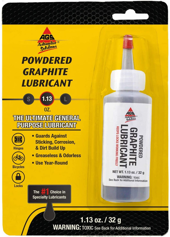 But I would not think other brands would cause a problem. I don’t k ow about the quartz. I haven’t been too helpful, all I can say is using the AGS graphite, my cavities are quite conductive. That’s from this frets thread: guitarnuts2.proboards.com/thread/9306/make-own-shielding-paint?page=1Sorry, I hid my terrible remembrance in this spoiler: (There was black paint, probably black nail polish, and some small canister of iron flakes/powder from Ace Hardware; I mixed those two together, removed most of the hardware, painted, and now have an electronics cavity where the paint completely lining the walls IS conductive.)
Though, remember… my problem had a major relation to the external ground loop I had created in my room; but, after the painting and reassembly, my guitar was at a somewhat quieter state, you know bc my external ground loop still existed! |
|
kitwn
Meter Reader 1st Class

Posts: 95
Likes: 23
|
Post by kitwn on Apr 13, 2024 19:00:10 GMT -5
Thunderoad,
Welcome aboard, you're in the right place if you want to experiment with guitar electrics.
If you're so new to the subject that you're not even sure what 'series' means then I strongly advise you to learn a few basics of electrical/electronic circuit theory before you start wielding the soldering iron. A quick search for electronics 101 brought up a pile of links including the YT video linked below. I haven't watched the whole thing but it looks like a good enough place to start.
Having some basic knowledge in your head will help you understand what you want to do and why. A few hours study will save you many hours of fruitless experimenting inside your guitar and possibly save some components being damaged by the repeated heating from a more experimental approach. If you watch/read something you need clarification on then there are plenty of willing helpers on this forum.
Learning some basic electronics will not give you all the answers to the ultimate guitar tone, but it will help you to work out the right questions.
Kit
|
|
|
|
Post by guitarnerdswe on Apr 13, 2024 11:22:13 GMT -5
In the video clip, I'm using a battery powered amp, with the mains power cut off in the entire apartment except for that room, plus everything in that room disconnected from the wall sockets. Hello again guitarnerdswe, A few additional queries: 1. You say that you are using a battery powered amp, and so there will be no connection to a domestic ground or earth. What effect on noise, if any, does a connection between the guitar ground and the domestic ground, produce? 2. Have you checked for continuity between the guitar ground - i.e. the circuit board ground, and the conductive paint lining the control cavity? 3. Check for continuity between the ground connection of the jack at the amp end, and the guitar circuit board ground. Hi! Sorry for the late reply.
1. I A/B:d recorded clips with the whole signal chain connected to domestic ground, vs the domestic ground disconnected. The grounded clips have less overall noise, but the backplate still adds about the same amount of noise when it gets close to the guitar.
2. I tried to, but I couldn't get a reading on it since it's a underneath a clear coat layer. I have another Music Man that has a patch where bare black paint is accessible, and there is no continuity even within the paint itself, so I'm not sure if it's even conductive paint to begin with it? It doesn't even cover the entire control cavity, and on the newer guitars they've skipped it entirely.
3. Yes, there is continuity all the way from the circuit board (and backplate) to domestic ground at the power outlets.
I also tried swapping cables, batteries, lifting the domestic ground on just the guitar rig, and lifting audio ground, no change in the noise.
|
|
|
|
Post by stateofepicicity on Apr 13, 2024 9:31:14 GMT -5
reTrEaD The compass I used to test polarity was sitting out on my work table, when I noticed a peculiar thing, the needle was pointing south! I hadn't even considered my compass might have had its polarity reversed at some point. So that means my outer coils are actually South. This doesn't change my last diagram other than the labelling of the polarity, but it's interesting to know that the neck pickup's color codes are as one would expect, with Schecter using Duncan's codes, but it's the bridge which is reversed.
|
|
|
|
Post by cynical1 on Apr 13, 2024 6:38:59 GMT -5
 Logical . . . but frightening. Logical . . . but frightening.This kid appears to exhibit conspicuous political aspirations... HTC1 |
|
|
|
Post by antigua on Apr 13, 2024 2:40:00 GMT -5
I like the sweep I get with a higher value tone cap. I sometimes even use .1uF caps. The lower peak is very bass-y, but the sweep range itself feels very usable. More recently I wired in a push pull with a 1nF to 3nF parallel cap in order to simply drop the resonant peak by some amount to get a more "humbucker" like cut-off. The main problem is mostly my forgetting to ever use that feature. I try lots of tone options but then find myself forgetting they exist, so I leave them out of future rewiring projects.
|
|
|
|
Post by JohnH on Apr 12, 2024 18:49:59 GMT -5
That sounds right. So it's a one-lane path from volume pot through the tone pot , through the tone cap, to ground. Break the path anywhere eg by removing the cap and no treble can bleed away. The no-load pot does this by breaking the circuit as the pot gets to 10, then below 10 its like a normal pot.
My HSS has a single master tone pot which is 250k no-load, and I also have some interesting blending features using what was the second tone pot. I have a 250k volume pot. I find that the 250k no-load is fine, and it gives the full bright disconnected no-load sound the same as a 500k no-load would. As it goes from no load to 250k, it's a very small tone step so I don't feel I need to subdivide it with a 500k. If you found with your cap/no-cap test that it was just a small (but useful) step, then you might conclude the same.
|
|
Deleted
Deleted Member
Posts: 0
Likes:
|
Post by Deleted on Apr 12, 2024 16:56:44 GMT -5
Thank you.
I think I understand. So, when one lead of the cap is soldered onto one of the lugs of the pot, and the other lead is grounded to the case of the pot, is that considered "in series?" I thought the pot itself could bleed off treble, but you are saying that it's the cap the does it, with variability of the pot. Correct?
I liked the uncapped sound of the humbucker, but it wasn't a huge difference from with the cap. I will look into the no load pot, as it seems like something I could like. With a humbucker, do you use a 500k no load pot?
|
|
|
|
Post by JohnH on Apr 12, 2024 16:19:51 GMT -5
Hi @thunderroad and welcome to GN2
The usual tone circuits on guitars work by the pot joined end-to-end in series with the cap. This bleeds some treble to ground, reducing the brightness, through the cap and controlled by the pot. So if you remove the cap, the whole thing becomes ineffective.
I like HSS guitars, I think they can be a perfect mixture of tones. There's no right or wrong way to wire them (so long as it works!), but there's always a choice between keeping the brightness in the thick-toned humbucker, vs taming the treble of the singles.
I quite like using no-load pots for treble, that cut out at 10. If you tried without the cap with your bridge tone, apart from the fact thst the pot didn't work, what did you think of the slightly brighter tone? There are ways to have that with no-load pots and still have tone control.
|
|
Deleted
Deleted Member
Posts: 0
Likes:
|
Post by Deleted on Apr 12, 2024 14:05:36 GMT -5
I bought an inexpensive HSS strat the had tone1 wired to the neck pu and tone2 wired to the middle pu. I decided to learn hands on about guitar wiring and wire tone2 to the bridge/humbucker and tone 1 for both neck and middle. That was fairly easy, but all three pots are 250k and each tone pot has a wired .047 cap on it. That works OK for the single coils but the combination seemed restrictive on the humbucker. So, I thought lets remove the cap on tone2 for the humbucker. My logic (ignorance) was less resistance = more tone for the humbucker. After removing the cap, the tone control for the humbucker did absolutely nothing. I soldered it back onto tone2 and it's working again. So does this mean that the pot is not working? Or, have I misunderstood how this all plays together? I'm trying to understand all this.
Thanks
|
|


 Now I remember “Faraday cage”; thank you


 to The NutzHouse!