|
|
Post by wolf on Sept 2, 2010 23:58:11 GMT -5
I think it is time to mention what this person's website has to say about this: www.neighborhost.com/scrapbook/pickup-id.htmlI tend to agree with that opinion and it might be worth looking over that page. I've rewired a lot of guitars and I never had to determine magnetic polarities, coil winding direction or starts or finishes in order for the wiring to be done correctly. |
|
|
|
Post by JohnH on Sept 3, 2010 3:21:01 GMT -5
Wolf – I would normlly agree. But in this case Im still stuck. This desgn needs the coils to be switched in a particular sequence, and the coil poles have to be placed alternately north/south/north etc. The latter has been worked out, and it doesn’t really matter whether is NSNSN or SNSNS. But we also have pickups that have similar looking poles, so if we want to engage, say the coil nearest the bridge, we don’t know if it is a north or a south, and nor do we know if it would be wired as a slug or a screw coil, for the purposes of picking the right pair of Dimarzio wires. One more piece of info is needed to make it all fall into place.
So, as you suggested mclord, how about getting a compass, and hold it against the top of the middle pup, to see whether it says the the middle pup is a north or a south? Then I think we know all we need.
John
|
|
mclord
Meter Reader 1st Class

Posts: 71
Likes: 0
|
Post by mclord on Sept 3, 2010 6:37:06 GMT -5
OK, I will get a compass today and test. But I want to understand the problem of whether to choose Slug or Screw pole. I thought as Wolf exactly. How does it matter ? Also, what do you mean by wiring it as Slug or Screw ? I am sorry, but my knowledge about guitar pickups is below needed  EDIT: EDIT:Does this mean that my D-activator X has 2 slug coils ? May the above paragraph help with something ? However, I feel he is wrong with the slug coil and signal delivery. |
|
|
|
Post by JohnH on Sept 3, 2010 7:43:57 GMT -5
Theres nothing really significant about the slug and screw coil thing. Its just that screw coils are adjutable and slug coils arent. In this case, the only significance is that it is a means by which manufactueres describe which colours of wire connects to which coil, and that is what we are now working out. If tyou happened to have pickups with one adjustable and one non-adjustable coil, we would know directly which wires to use for esch.
Its more sugnificant to make sure we have pairs of coils selected that are of opposite north/south polarity.
With those, we wire one coil in the opposite direction to the other, to cancell hum, but if that coils has an opposte magnetic field through it, the sound phase is not reversed when we reverse the coil. So hum cancells out, and the sound signal does not. - which so far is looking good on this design.
|
|
mclord
Meter Reader 1st Class
Posts: 71
Likes: 0
|
Post by mclord on Sept 3, 2010 10:37:22 GMT -5
I see, so the whole matter now is to know which pair connects to which coil, Right ?
I think since we know that Red/Black are connected to Northern Coil and White/Green is connected to Southern coil. This will make stuff easier. All we need to know now is where is the North and where is South ? Am I following right ?
|
|
|
|
Post by JohnH on Sept 3, 2010 15:35:25 GMT -5
yes, thats all its about. Nearly there!
J
|
|
mclord
Meter Reader 1st Class
Posts: 71
Likes: 0
|
Post by mclord on Sept 4, 2010 15:07:21 GMT -5
Well, I am confused. how placing the compass over the middle pickup help ? I didn't get it actually.. Can you illustrate for me please ? Sorry for questioning a lot |
|
|
|
Post by JohnH on Sept 4, 2010 16:17:19 GMT -5
Well, I am confused. how placing the compass over the middle pickup help ? I didn't get it actually.. Can you illustrate for me please ? Sorry for questioning a lot I think like this would work:  and as shown there, that would be a 'north' coil John |
|
mclord
Meter Reader 1st Class
Posts: 71
Likes: 0
|
Post by mclord on Sept 4, 2010 18:05:29 GMT -5
According to your sketching - which is very neat. I like they way of your sketching  Here we go ...  So what is the next step ? |
|
|
|
Post by JohnH on Sept 4, 2010 18:17:02 GMT -5
Right then! - with that finally worked out, we now know how to place the humbuckers (ie, as your diagram), and since we know the polarities of each coil, we can know which colour wires go to each coil, based on DiMarzio data.
The base design is at post 40, but realtive to that, all the colours need to swap. Ill do that soon.
Any further thoughts on the switching (given that I couldnt make the out/out be all off as you asked)?
John
|
|
mclord
Meter Reader 1st Class
Posts: 71
Likes: 0
|
Post by mclord on Sept 4, 2010 18:51:46 GMT -5
No there is no more thoughts, however about the out/out setting. Is it possible to ground all pickups so signal is sucked for example therefore no output ?
Something more, while wiring I may fall into a problem, Out of Phase problem because of the Coil Winding. We have Reverse Polarity but I can not guarantee Reverse Wound. I know this could be fixed by swapping Hot with ground and vice verse. Am I correct ?
|
|
|
|
Post by JohnH on Sept 4, 2010 19:50:36 GMT -5
No there is no more thoughts, however about the out/out setting. Is it possible to ground all pickups so signal is sucked for example therefore no output ? That's what I was trying to do, but we have no spare switch poles to do it. I think, having sorted out the magnet directions, we can trust DiMarzio that the wire colours corespond to their standards. So the Hb wiring should be OK The middle pickup, we can now expect will either be correctly in-phase and humcancelling with the other coils, or it will be out of phase and non-hum cancelling. This can be corrected just by swapping its wires if needed, without affecting anything else. If you want to, you could try to test for this first however, like this: guitarnuts2.proboards.com/index.cgi?board=reference&action=display&thread=4938' Or just try the build, and allow to swap the middle pickup wires if needed. And here's the diagram:  cheers John |
|
mclord
Meter Reader 1st Class
Posts: 71
Likes: 0
|
Post by mclord on Sept 5, 2010 1:03:58 GMT -5
Thanks a lot John. You really worked hard on this. I will implement it this weekend. Just a question, what are the another possibilities you may have in Out/Out without need to extra poles or switches ? I mean different combination but without effect on the other 3 configurations.. Also this wire  |
|
|
|
Post by JohnH on Sept 5, 2010 1:08:07 GMT -5
Just a question, what are the another possibilities you may have in Out/Out without need to extra poles or switches ? I mean different combination but without effect on the other 3 configurations.. Theres nothing else I can suggest with those switches, without messing with the other settings! Good luck with the build John |
|
mclord
Meter Reader 1st Class
Posts: 71
Likes: 0
|
Post by mclord on Sept 5, 2010 1:15:53 GMT -5
I see, so it is like a a garbage of the other combination. No problem, although it annoys me  I just edited my post ... Please recheck it Thank you |
|
|
|
Post by JohnH on Sept 5, 2010 1:58:06 GMT -5
the highlighted green wire goes just as shown - from a lug on the 5-way to a lug on the push/pull. maybe I dont understand your question?
EDIT - i see there is a tiny gap at the end of the wire, but yes it should go to the switch lug.
Grounded wires to be soldered to the pots are shown at the top of the switches. In this position, you will see that a push/pull pot has a lug that is part of the case to solder to.
J
|
|
|
|
Post by JohnH on Sept 5, 2010 2:33:16 GMT -5
hhmmmmm.....maybe there is a way to get that dead setting if you pull both out (damn!)
See the blue wire that goes from one p/p switch to the other? just move the left end from top right lug to centre right lug!
I think it does it - see if you agree
John
|
|
|
|
Post by JohnH on Sept 5, 2010 3:15:09 GMT -5
like this..... 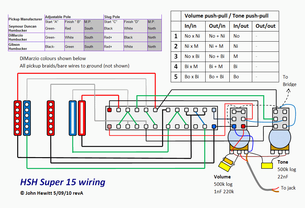 |
|
mclord
Meter Reader 1st Class
Posts: 71
Likes: 0
|
Post by mclord on Sept 5, 2010 13:44:36 GMT -5
I hope this works, but even if it doesn't I won't be annoyed that much All I care about is the other 3 configurations. You have done a lot of effort on that scheme and I will provide feedback as soon as this diagram is got applied  Thanks a lot John |
|
mclord
Meter Reader 1st Class
Posts: 71
Likes: 0
|
Post by mclord on Sept 14, 2010 16:40:53 GMT -5
I just started today to wire and solder, but I have a problem with soldering on the top of the pot. There is no pins to insert the end of the wire into and solder.. I am just soldering on a plain plate. So do you have any suggestions about this problem ? EDIT: I found that the back of the pot needed to be clean using a sandpaper to remove a coating at the back. Well 6 seconds max. using a 40W Soldering Iron but as I felt it began to become to hot, I moved it away... Is there a chance of my pot being damaged .. Since it is a P/P pot, I think the plastic wiper and the brass resistance wire are far from the back or am I wrong ? Also, Do I solder the bare wire for Neck and Bridge pickups on the back of the Volume pot -The Middle pickup has no bare wires - ? Thank you |
|
|
|
Post by newey on Sept 14, 2010 19:28:57 GMT -5
You can certainly damage a pot with excess heat. If you have any question, check it with a multimeter before trying again.
Most p/p pots have a little nub or tab sticking out at the rear end for soldering ground wires onto. Otherwise, roughing up the surface is the way to go, as you discovered.
Any pot is fine to use, so long as all the grounds you have are collected in one place, or at least somehow connected together.
|
|
mclord
Meter Reader 1st Class
Posts: 71
Likes: 0
|
Post by mclord on Sept 14, 2010 19:59:24 GMT -5
Excuse me, How can I check ? Connect one lead to the first lug and the other lead to the middle lug and turn left or right the knob, so it should have decreasing or increasing resistance with no dead spots in the middle as I turn left or right ?
EDIT: One more question, should be all wires at the back of the pot soldered in one joint or can I make 2 or 3 joints assuming that the back is made of metal which is a conductor of electricity ?!
|
|
|
|
Post by newey on Sept 14, 2010 20:34:05 GMT -5
Multiple connections are fine.
Basically, yes. At one extreme of rotation, you should get a value close to the rated value, at least within the tolerances (usually ±20%). At the other extreme, it should be a very low resistance, just a bit above 0Ω. In between, it should vary between the two, keeping in mind that a log taper will behave differently than a linear one.
|
|
mclord
Meter Reader 1st Class
Posts: 71
Likes: 0
|
Post by mclord on Sept 14, 2010 20:44:20 GMT -5
Yea, sure, in 50% position I won't get 250K because it is logarithmic.. I will check it tomorrow and I will inform you.. I hope no damage occurred EDIT: I opened the back of the pot, I can see the Push/Pull pins fitting in a black plastic box. I see at the other face of where I have soldered a greasy yellowish substance - Internal face -? What is that ? |
|
|
|
Post by JohnH on Sept 15, 2010 15:41:07 GMT -5
Ive never opened a p/p pot. can you get it back together?
For soldering to it, the diagram shows wires soldered to the case at the top of the switch section - ie, not near the actual pot. as newey said, there should bea small projection of metal case to solder to. 'Tin' it first by applying solder to it, then tin the wire ends themsleves, then put them on the metal tab in contact and melt them all together, adding a bit more solder. It should not matter that there is no hole to put wires through, a good contact solder joint sholdbe stronger than the wires themselves.
John
|
|
mclord
Meter Reader 1st Class
Posts: 71
Likes: 0
|
Post by mclord on Sept 15, 2010 16:43:15 GMT -5
No.. The pot itself has something like a door at the back.. I can disassemble a pot, but surely, I won't be able to get it back again. Do you mean I solder here ? I have already roughened the surface and soldered in this place. (This is not my pot. Just an Image from the internet but exact same p/p pot)
 The Volume pot looks like a bomb right now.. It has too may wires and the space between P/P contact pins is too small.. I hope that design works, because de-soldering and soldering in another place would be near impossible. Thanks |
|
|
|
Post by JohnH on Sept 15, 2010 19:15:30 GMT -5
Electrically, you could solder your grounds to any matal part of the pot case. On your photo above, just above the patch that you point to, it looks like there is a small projecting lug coming off the case? If so, that would be what Id suggest.
Sometimes, as an alternative. I put a washer around the shaft of the pot, with a bare wire presoldered to it. Then the bare wire goes to a nearby point on the switch or pot lugs that needs to getget grounded, then other grounded wires can be soldered along that bare wire.
|
|
mclord
Meter Reader 1st Class
Posts: 71
Likes: 0
|
Post by mclord on Sept 15, 2010 20:01:59 GMT -5
I see have that lug too.. So you recommend soldering to it. Alright. I think soldering to that lug is my option Do you think that soldering to this lug is more better than the point I have soldered too ? I am not satisfied with the solder, so I will remove it and solder again at this point. Thank you. I will inform you with more details as I advance in soldering.. |
|
|
|
Post by JohnH on Sept 15, 2010 20:22:53 GMT -5
I see have that lug too.. So you recommend soldering to it. Alright. I think soldering to that lug is my option Do you think that soldering to this lug is more better than the point I have soldered too ? I am not satisfied with the solder, so I will remove it and solder again at this point. Thank you. I will inform you with more details as I advance in soldering.. All you need is a good liquid-looking joint. Its easier to make a good joint to a lug like that beacuse being fairly small, you can heat it up easily so its hot enough to melt the solder, and less heat spreads to the rest of the case. BTW - for a good solder joint, the solder should melt on the metal of the components, not just on the iron. So, pre-tin the parts, a bit of solder on the iron to help contact, iron heats the work, and a bit more solder melted on the work and it all flows like a liquid pool without beading. Then pull off and hold steady while it sets. |
|
mclord
Meter Reader 1st Class
Posts: 71
Likes: 0
|
Post by mclord on Sept 15, 2010 20:41:21 GMT -5
Yeah.. I get that look of a metal liquid ball then the solder melts on the metal of the pot and the wires. Well, I have not tinned the wires before... All what I do is wait for the pencil to heat.. then expose some of solder to see it reached the melting point (is that tinning the solder iron ??!).. then I put the solder close to the wire and begin to melt some solder getting that liquid metal ball over the wires and it solders pretty well.. But I will pre-tin the next solders I hope all the previous solders are fine and no cold joints.. or what ? Thanks for the advice. I always learn new stuff from every post of yours and newey's . Thanks a lot |
|


