|
|
Post by Mini-Strat_Maine on Jun 13, 2006 12:50:32 GMT -5
I'm about ready to stop messing around with the cheeseball plastic input jack on my stepson's Danelectro "Nifty Fifty" amp. As several reviewers of Dano amps have said, a plastic jack with a metal nut is not a real swift idea. Even if I could find the right-size nut for that ( 29/ 64" i.d., I think), I don't think it would hold up for very long.  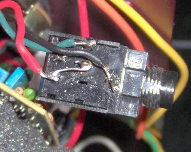 I had hoped a Radio Shack 274-312B (three-conductor, mostly metal) stereo jack could replace the stock part, but the five terminals on the plastic one kinda complicate things. (One jumper between two terminals is visible in the pic, another goes from the terminal where the green wire is soldered, to a terminal hidden by the black wire.) The jacks in the pic between items 8 and 9 on this page www.angela.com/catalog/guitar-amp-parts/INPUT_JACKS.html look a little more reliable than the Dano part, but they have either four or nine "blades" for terminals, and that's more than I want to mess with. There may be something suitable in the Mouser catalog, but getting the wires soldered to the right places (and rigging any required jumpers) could be more fun than I could stand. Other than epoxying it to the chassis, anyone got any ideas? And if a three-conductor jack will work, any suggestions for where red, green, and black would go, meaning tip-ring-sleeve? |
|
|
|
Post by UnklMickey on Jun 13, 2006 13:24:17 GMT -5
Doug,
it's hard to know what's up with that jack without seeing a schematic.
normally an input to an amp has 2 wires, and the jack is switched (shorted when no plug inserted). but i'm not sure what's going on with that one.
from what i've heard, it isn't likely you'll find a schematic for anything Danelectro either.
so if you're real lucky someone will have some info regarding that jack.
otherwise, you might do some careful physical examination/ electrical measurement of that jack, and determine exactly how it functions.
unk
|
|
|
|
Post by Mini-Strat_Maine on Jun 13, 2006 14:28:00 GMT -5
from what i've heard, it isn't likely you'll find a schematic for anything Danelectro either. Nope; been down that road already. I dunno about "careful," but I think I could open its case. (That part would be easier if it was transparent, like the ones on the Angela page.) I do have a short stereo cable around (the foot controller for a Uni-Vibe needs one to work right), and I'm guessing that'd be my best bet for electrical measurements. I was gonna ask how to go about that, but I'm gonna just go ahead with what I think is the right procedure, and check back later. Thanks for the idea. |
|
|
|
Post by UnklMickey on Jun 13, 2006 14:32:27 GMT -5
but I'm gonna just go ahead with what I think is the right procedure, and check back later
that's what we like to see, initiative.
just don't slice and dice, until you come up with a suitable replacement.
|
|
|
|
Post by Mini-Strat_Maine on Jun 13, 2006 15:31:06 GMT -5
just don't slice and dice, until you come up with a suitable replacement. Right; kinda like the old "measure twice, cut once" thing.  Well, with the stereo cable in the jack, multimeter sez {DING!}: the red wire appears to be tip. The green one and the black one each appear to be both ring and sleeve. (Assuming I put the test clip on all the right places on the "free end" plug.) I'm starting to suspect that Danelectro used the same parts for both input and headphone jacks, and maybe the jumpers set up whether the jack would be NO or NC. (The headphone jack has its "blades" inserted into a PC board.) Would it be a good guess that the headphone jack is NC, opening the connection to the speaker when the 'phones are plugged in? |
|
|
|
Post by UnklMickey on Jun 13, 2006 15:43:15 GMT -5
that all seems to make sense so far.
when the plug is removed, is there continuity between the red and/or the black / green ?
|
|
|
|
Post by Mini-Strat_Maine on Jun 13, 2006 16:04:53 GMT -5
that all seems to make sense so far. Now, that's kinda scary.  Yep, with both. Black and green also seem to be connected. Plugging in a "plain" (T/S) cable, black and green still seem to be connected, but red is isolated from either of the others. |
|
|
|
Post by UnklMickey on Jun 13, 2006 16:24:04 GMT -5
scary is.
(i think i'm chanelling Chris today)
for what it's worth, i'd replace it with a simple mono switched jack.
join the black and green at the jack. BOTH connect to the sleeve and the switch that shorts the tip.
red connects to the tip.
if it mounts on a plastic panel, good enough.
but if it mounts to a metal chassis, i'd probably add an insulated shoulder washer and insulated flat washer, to avoid a ground loop.
unk
|
|
|
|
Post by UnklMickey on Jun 13, 2006 16:35:14 GMT -5
.... Black and green also seem to be connected.... i think that's because black and green are connected at the other end. either locally, or at different points on the ground circuit. unk |
|
|
|
Post by Mini-Strat_Maine on Jun 13, 2006 16:51:49 GMT -5
for what it's worth, i'd replace it with a simple mono switched jack. join the black and green at the jack. BOTH connect to the sleeve and the switch that shorts the tip. red connects to the tip. Okay, thanks. I'll give that a shot tomorrow, after I get all the parts. It's on metal; probably the one good thing about their cheeseball plastic jack. I wondered about a problem with that, but I'd never have come up with "ground loop" on my own. I had been using a rubber washer over it, one that was kind of a press fit, and was going to try one on either side of the hole. (The RadShack jacks have a more generous threaded section than the originals do.) If the shoulder washer is what I think it is, that might help keep it from slopping around in the hole, and maybe making unwanted contact through the threaded section. I'll go with those suggestions for "long-term performance and reliability."   |
|


