masterluke
Rookie Solder Flinger

Posts: 8
Likes: 0
|
Post by masterluke on Nov 10, 2006 0:11:03 GMT -5
Hi all, Long time reader, first time writer. Great site. I have a problem that I hope could be solved by you folks. I recently completed building an electric guitar with Fender Telecaster Vintage Noiseless pickups. The pickups have one black wire and one yellow wire each. It has a 3-way switch, a volume knob and a tone knob. The problem i am having is that i can select either of the two pickups using the switch just fine, but when I put the switch in the middle position, the sound is so faint that you would hardly think it's plugged in. Definitely a wiring problem, but I followed the wiring diagram supplied perfectly and still it virtually cuts out all sound when i try to select both pickups on the middle position. Here is the wiring diagram that came with the pickups. s136.photobucket.com/albums/q176/mamaindia/?action=view¤t=televintagenoiselesswiring.jpg&refPage=&imgAnch=imgAnch1Thanx stacks! Luke. |
|
|
|
Post by UnklMickey on Nov 10, 2006 17:57:02 GMT -5
hi Masterluke,
welcome to GuitarNuts2
use the force Luke your eyes. if you wired as shown, only the hot leads are being switched. so it might not be exactly a wiring error. it could be the one of commutators of the switch is rubbing against something grounded when you get to the middle position.
cheers,
unk
|
|
masterluke
Rookie Solder Flinger
Posts: 8
Likes: 0
|
Post by masterluke on Nov 11, 2006 17:07:59 GMT -5
Thanks unklmickey, I agree that the wiring is probably ok as so many versions of telecasters have similar wiring. As for the possibility of the switch or other components touching the shielding, i tried taping around the susceptible areas to avoid any contact, but the problem is still there. I have wired and rewired the guitar about 6 times in the past 2 days and have come to a final wiring outcome. Now when the neck pickup is selected the sound is great and the volume and tone work fine. When I select both pickups the very faint sound output remains. When I select the bridge pickup the volume is ok but the tone also acts as a volume. It seems that no matter which way i wire the guitar i cannot get both pickups working properly, or together. The pickups are only about 6 months old and have never been cranked. All the components are virtually new. Sorry for the lengthy message but any further help would be really appreciated. I have attached some more pictures of the internals. 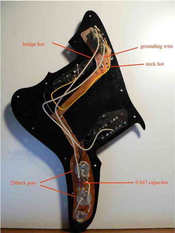 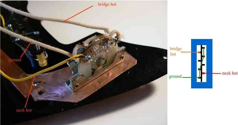 ![]()  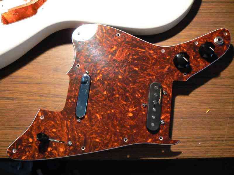 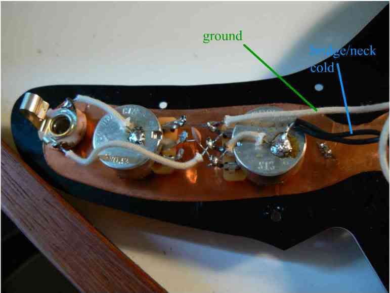  Thanks. Luke. |
|
|
|
Post by JohnH on Nov 11, 2006 20:13:40 GMT -5
|
|
Channelman
Meter Reader 1st Class

Posts: 62
Likes: 0
|
Post by Channelman on Nov 12, 2006 14:14:14 GMT -5
Looks OK to me as well. Only thing is, on 3 of the photos
you have labeled a wire as 'ground'....it isn't. A more appropriate
name would be 'switched hot'.
You could try this....
With the unit out of the guitar, connect it to an amp
and test neck/bridge/both positions by touching the PU poles
with a screwdriver. This would eliminate any 'shorting to the
shielding' from the equation if the 'click' level is similar in all
three switch positions.
|
|
|
|
Post by ChrisK on Nov 13, 2006 12:54:39 GMT -5
Also, the pots are 250Kilo Ohms and not 250 mA (milliAmperes).
John H's suggestion of a multimeter is the way to go. Any guitar wiring work or troubleshooting REQUIRES one. Not using one is akin to driving while looking the rear view mirror only. You won't know where you're heading, only where you've been.
I would compare the readings for each pickup selected alone (one DID measure the coils of each pickup prior to starting to ascertain their continuity?) to the expect/measured for each pickup "out of body/circuit". This should be done at the output jack with all pots set to full CW
The bridge nominally is 8.6 K ohms (8,600 Ohms, 8K6 fer you Europeans oot there).
The neck nominally is 12 K Ohms.
The middle position (both pickups selected in parallel) should read aboot 5 K Ohms.
I notice what appears to be a glob of solder on the top cover of the neck pickup (?). Also, from what I can discern from the pics, your solder joints appear to be somewhat cold. There also appears to have been a lot of heat applied to the solder joints.
If all else checks out, you may want to clean the solder joints (and switch contacts). Depending on where one resides on this planet some solder has fairly crappy flux within (one DID use electronic solder with a flux core and NOT a solid plumbing solder with external [highly corrosive] paste flux?). Such flux can be electrically conductive.
I use rubbing alcohol for this (but rarely for rubbing). ;D
Also, you didn't use RoHS solder which has no lead within, I hope. This will cause "wetting" issues with tin/lead plated parts.
(RoHS, or the European MANDATE for Reduction of Hazardous Substances [i.e. lead] from all things, is thought to possibly be causing more pollution issues than it was believed to correct.)
|
|
masterluke
Rookie Solder Flinger
Posts: 8
Likes: 0
|
Post by masterluke on Nov 13, 2006 17:24:07 GMT -5
Thanks ChrisK for the reply. Firstly, there is no solder on the cover of the neck pickup  - camera trick. And the solder I did use was some quality stuff. And to Channelman, I don't know where that "grounding wire" came from. Thanks for pointing that out. Secondly, I am no expert in checking the resistance values. You say check the resistance from... the hot wire of the neck pickup to the hot part of the output jack?? or from the one of the poles of the pickup to the hot output jack? Also how would you check for both pickups selected? Where would you put the +ve and -ve terminals of the multimeter?  Sorry for the elementary questions, evidently electronics is not my strong suit. Thanks again. Luke |
|
|
|
Post by ChrisK on Nov 13, 2006 17:48:34 GMT -5
would be the way to check the continuity of that connection.
I would measure directly across the output jack or from the volume pot ground terminal to its wiper.
Put all pots at full ClockWise.
Select the bridge pickup on the selector switch.
Measure resistance and compare to my earlier post.
Select the neck pickup on the selector switch.
Measure resistance and compare to my earlier post.
Select the bridge and neck pickup (both) on the selector switch.
Measure resistance and compare to my earlier post.
Results are. Posting is.
|
|
masterluke
Rookie Solder Flinger
Posts: 8
Likes: 0
|
Post by masterluke on Nov 13, 2006 19:52:21 GMT -5
Hi guys, I have tested the wiring with my multimeter by checking the resistance from the hot wire on the pickups to the hot output jack, with the pots turned clockwise fully. These are the results: With the Neck Pickup selected I get 10.35K Ohms With the Bridge Pickup selected I get no response. However I get a resistance reading of 10.8K Ohms from the neck pickup. With both pickups selected, the neck will give me 10.8K Ohms again, and the bridge will give me nothing. Hope I have done this right.  Luke. |
|
|
|
Post by ChrisK on Nov 13, 2006 22:22:29 GMT -5
I don't understand this statement. You're NOT doing what I said.
Ok.
I don't understand this statement. What does it mean to get "no response from the bridge and 10.8K from the neck"? How can you tell what is what? Does "no response" mean 0 Ohms (a short) or infinite Ohms (an open)?
I don't understand this statement. What does it mean to get "no response from the bridge and 10.8K from the neck"? Again, what does no response mean?
OK, here we go.
With one lead of the Ohm meter connected to/touching the mounting nut on the output jack (circuit ground/common) and the other lead connected to/touching the hot lead on the output jack, and all pots fully CW, what do you read (sans any inferences or deductions) on the following:
Bridge selected _____ K Ohms (between 0 and infinite)
Both selected _____ K Ohms (between 0 and infinite)
Neck selected _____ K Ohms (between 0 and infinite)
I must have just this exact information. Raw data please.
(BTW, a reading of 10.35 K and 10.8 K does indicate a parallel resistance of 250 K across a 10.8 K resistance in the 10.35 K instance.)
|
|
masterluke
Rookie Solder Flinger
Posts: 8
Likes: 0
|
Post by masterluke on Nov 14, 2006 2:34:00 GMT -5
ChrisK,
Sorry i misread your previous reply.
Neck: 10.5KOhms
Bridge: Infinite at full volume.
~19.6 at 1/2 volume (this number jumped around a bit)
0 at no volume.
Both: Infinite at full volume.
~19.6 at 1/2 volume (this number jumped around a bit)
0 at no volume.
Is this any help?
|
|
masterluke
Rookie Solder Flinger
Posts: 8
Likes: 0
|
Post by masterluke on Nov 14, 2006 17:10:23 GMT -5
Another thing, after removing the bridge pickup and testing its continuity. See image below. 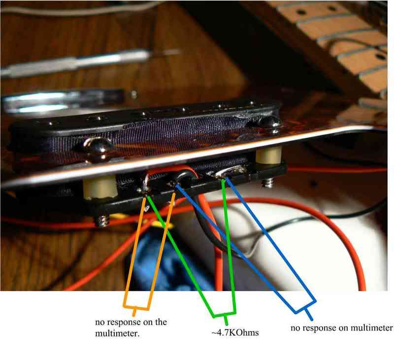 The neck pickup gives me a reading of 10.8KOhms on the leads. Luke. |
|
|
|
Post by ChrisK on Nov 14, 2006 23:24:22 GMT -5
Ok, the neck switching and pickup is working.
Are you sure that you're not reading 250K Ohms?
You're reading the volume pot at half on.
You're reading the volume pot at off.
You're not switching in the neck pickup in this position.
Analysis:
1. Your latest photo confirms that the bridge pickup is damaged. The surgical rubber tubing (I a$$ume that what you used are rubber) for bridge pickup mounting touches the very fine winding wire on the pickup at each mounting position. I used a nylon shoulder washer on each screw specifically to avoid any touching of the fine wire when I installed one in a Tele. I'm surprised to see a red wire on a Fender Tele Noiseless pickup. Your earlier photo showed a white wire on the bridge pickup. Mine had a yellow and black wire. Did you solder any wires to the pickup? It is very easy to damage a solder joint connecting to the fine coil wire. This is why pickups come with wire leads.
Anyway, it's dead.
2. In the "both selected" position you're not connecting the neck pickup into the circuit. I don't know if you're connecting to the bridge also since it has an open coil. Your switching circuit is either wired incorrectly or the repeated re-soldering has damaged at least the switch.
3. I wonder what wattage soldering iron that you used. I use a 40 watt one that also has a 20 watt setting. The selector switch looks cooked in your photo. Many of the solder joints appear to be cold, and may have questionable continuity. Did you pre-tin the wires (if not silver colored) with solder? Are you using rosen core electronics solder and not plumbing solder and corrosive flux?
I'd start over, plan thrice and solder once.
|
|
|
|
Post by UnklMickey on Nov 15, 2006 1:24:30 GMT -5
hey guys,
i'll let y'all figure out what's up with the heath of the pickups.
the selector does look mighty stuffed, but did you notice the picture of the wiring is a mirror image of the Fender drawing ?
|
|
masterluke
Rookie Solder Flinger
Posts: 8
Likes: 0
|
Post by masterluke on Nov 15, 2006 8:17:53 GMT -5
hey unk, do you mean the my selector switch is a mirror image of the drawing? This is because they are opposite. If I had soldered the wires in a sequence that matches the drawing, there shouldn't be a problem right? As for the selector switch itself, I don't think it is affected at all. The photo was taken under poor lighting. All the contacts operate well. And to answer ChrisK's question, yes I am using decent electronics solder, and not plumbers solder. Also using a 20watt soldering iron. Ordering a DiMarzio bridge pickup to replace the noiseless tele. Regards. L. |
|
|
|
Post by UnklMickey on Nov 15, 2006 13:10:13 GMT -5
hey unk,
do you mean the my selector switch is a mirror image of the drawing? This is because they are opposite. If I had soldered the wires in a sequence that matches the drawing, there shouldn't be a problem right? ... i really can't tell from the photos, how the switch itself should be connected. i can only tell that the wiring is a mirror of the wiring in the Fender drawing. |
|
|
|
Post by ChrisK on Nov 15, 2006 19:00:31 GMT -5
It indeed looks like your switch wipers are the upper right and lower left terminals.
The Fender drawings presume that they are the upper right and lower left.
You have mirror-image wired the switch (thanks unk, yer eyes are much better than mine.) You have the neck hot going to the upper left and the bridge hot going to the lower right.
This might have occurred due to your being located in Australia. ;D
BTW Take a look at the damaged bridge pickup. If your gifted in micro-soldering surgery, you might be able to rescue it. Or, you could use it as a single coil. The Fender Noiseless pickups are stacked humbuckers wired in reversed series (the coil signals subtract) and either coil alone is hotter that both together, but not noise-canceling.
|
|
masterluke
Rookie Solder Flinger
Posts: 8
Likes: 0
|
Post by masterluke on Nov 15, 2006 20:24:32 GMT -5
to turn the pickup into a single coil would i need to just add a lead to the terminal on the other side of the pickup? (see pic) Since the spot where the black lead used to be is useless, but I still get a reading of 4.5KOhms from the red lead to the double terminal on the other side. 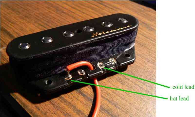 |
|
|
|
Post by ChrisK on Nov 15, 2006 20:30:19 GMT -5
Yeppers! Use minimal heat and attach a small gauge insulated tinned solid wire (#22AWG or smaller). I wouldn't try to remove the jumper, just lay the stripped end (1/4") alongside it and solder. I can't comment on the common and hot phasing that will result in comparison with the other pickup. Wire it up and if the "both" switch position sound weak and "tinny" sounding, reverse the bridge pickup wires AT THE SWITCH AND POT BACK. I've converted the same pickup to 4 wire, but I'm skilled in micro-soldering and I was vewwy, vewwy careful. 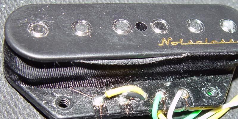 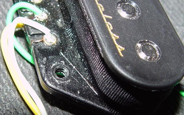 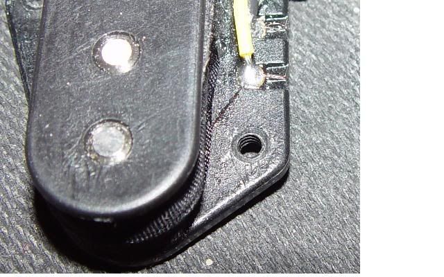 |
|
monradon
Meter Reader 1st Class
Posts: 52
Likes: 0
|
Post by monradon on Dec 5, 2006 22:28:57 GMT -5
This is not your question but I thought the highest number was by the bridge , less on the middle and the lowest number usually by neck when using three pickups ?? |
|
|
|
Post by UnklMickey on Dec 6, 2006 9:39:10 GMT -5
highest number at the bridge? you mean the resistance measurements that were discussed earlier?
if that's what you're saying, you have the right idea.
here's more info, so you can understand when that doesn't apply.
the deflection of the string as it vibrates, is smaller at the end (near the bridge, and near the nut or fretted end.)
so normally, all things being equal, the signal produced at the bridge is weaker.
how to compensate for this?
move the bridge pickup much closer, and the neck pickup much farther away.
but there is another way. many pickup sets have much of the compensation designed-in. they put more turns on the bridge, as compared with the neck. if there is a middle pickup, some wind it the same as the neck, others wind it somewhere between the number of turns on the neck and the number of turns on the bridge.
since more turns on a coil of a given size, with the same wire, will result in more resistance, you would assume that more resistance = more turns.
there are 2 other reasons why the resistance could be higher.
1 - if the size of the bobbin is larger, the resistance will be greater. same number of turns, but more length per turn.
2 - if the diameter of the wire is smaller, this increases the resistance for the same length of wire. same number of turns, about the same length per turn, but more resistance per turn.
my guess is these factors are both in play for the pickups we have been discussing. the neck coil is smaller, so that causes a decrease in resistance per turn. but the wire is a smaller diameter, so that means more resistance per turn. the bobbin size is having a small effect in this case, and the wire size a much larger effect.
also it is possible there are also MORE turns on the neck pickup than the bridge. the neck magnet might be weaker. i don't know this to be true, but it is another possible explanation.
so in a nutshell:
if all other things are equal, more turns = more resistance...........but sometimes, all other things are NOT equal.
cheers,
unk
|
|


 - camera trick. And the solder I did use was some quality stuff.

