dmt
Rookie Solder Flinger

Posts: 11
Likes: 0
|
Post by dmt on Sept 14, 2007 1:56:44 GMT -5
Anyone know how I can wire a guitar with 3 Humbuckers? I was searching for the "Gibson Black Beauty" wiring but i can find it.
I want to have 3 Humbuckers in parallel, possibly with the middle pickup out of phase, and with a separate volume control for each pickup. No tone. Doesn't need it any way. I am basically going to make a new pickguard for my strat and drop in 3 humbuckers. Its already routed for it so all i have to to do is make a pickguard and wire it. Not too hard. And i have a pair of Gibson Custom pickups (2 wire) and a Ibanez Axis (3wire) humbucker for the middle pick up.
Neck: Gibson Neck PUP
Mid: Ibanez Axis PUP
Bridge: Gibson Bridge PUP
3 volume pots.
Possibly a phase switch. All pups in series i think. Maybe a phase reversal switch. Any ideas?
Also a template for a pickguard would help.
|
|
|
|
Post by Runewalker on Sept 14, 2007 12:58:02 GMT -5
Not to dissuade you from your vision of 3 -hums in a Strat, but something to consider is an issue Unk usally raises in this type approach. 3 -Hums take up a lot of geography under the strings where the "picking channels" are. Typically I raise -Hums higher than single coils because the magnetic window seems more diffuse, and the single coils easily move into the dreaded "Stratitus" syndrome. With 3 -hums up close to the strings, you will have very narrow picking channels. Certainly with 3 -hums producing 6 single coils you could go GuitarNutz Nuttzy with options. However, your approach just mentions some simple arrays, so that does not appear the motivation. If it is just look you are interested in you may have to lower the mid pup to be able to pick, and that might compromise the sound produced by it. Consider one or more of the designs in the Schematics sections that use 2 -Hums, but are configured to allow inner-inner coil-cut combos, because that does a pretty good job of emmulating a phantom mid-humbucker. Risking being accused of shilling my own collaborative design (props to JH), this one does that and can be adapted to a Strat by useing a Tele 3 way lever switch: guitarnuts2.proboards45.com/index.cgi?board=schem&action=display&thread=1181507361also Unk's big ugly will do the inner/inners but with a 5 way specialty switch: guitarnuts2.proboards45.com/index.cgi?board=schem&action=display&thread=1139268111The 2 above go far beyond the options you describe, but are mythical in their tone options. There are probably others, including the PRS wiring scheme that do this (inner/Inner). But if it has to be 3 then Guitar Electronics has this one and at least one more: www.guitarelectronics.com/product/WDUHHH3T2201Probably SDuncan does as well but I did not look. Members here frequently caution that these stock designs leave something to be desire in terms of elegance. |
|
dmt
Rookie Solder Flinger
Posts: 11
Likes: 0
|
Post by dmt on Sept 14, 2007 17:24:55 GMT -5
You're saying that it may be hard to pick if i have to have the humbuckers closer to the strings? You may be right, but I want to give it a try anway. I dont think itll be a big problem. As far as coiltapping i cant do it with these pickups. The Gibson Custom pickups were taken from a Les Paul and were factory installs 2 wire pickups. There is no real way to make that work. I am sort of going for a non-traditional approach as an experiment.
|
|
|
|
Post by ChrisK on Sept 14, 2007 20:51:49 GMT -5
It's hard to pick 'cuz the humbuckers are wiiiiide and leave very narrrrrow vertical picking lanes. If you look at this body, you'll see that these are aboot 3/8" wide and only betwixt the humbuckers. Things ain't much better at the bridge or neck. They'll be no drifting aboot in search of finger tone (as in). 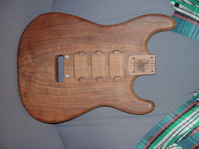 |
|
dmt
Rookie Solder Flinger
Posts: 11
Likes: 0
|
Post by dmt on Sept 14, 2007 23:15:59 GMT -5
A sacrifice to be made in the name of science. I can alwats switch the picguard and pickup assembly easily out and change it around if i dont like it. I plan to make two pickgaurds anyway, one ofr the three HB's one with just HH.
So any takers on a wiring diagram?
|
|
dmt
Rookie Solder Flinger
Posts: 11
Likes: 0
|
Post by dmt on Sept 15, 2007 18:05:29 GMT -5
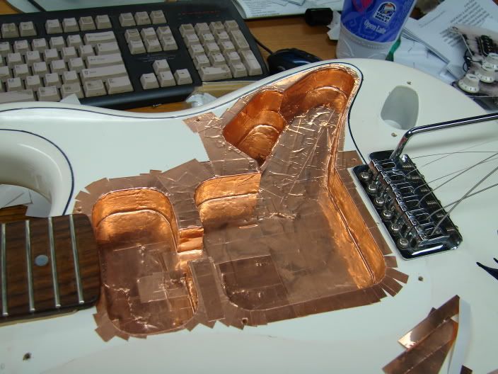
I just realized that I will need to route deeper holes to accomodate the longer humbucker supports. Its either that or modifing the pickups' supports. Not about to ruin a nice pair of gibson humbuckers...
|
|
dmt
Rookie Solder Flinger
Posts: 11
Likes: 0
|
Post by dmt on Sept 16, 2007 16:36:12 GMT -5
|
|
|
|
Post by ChrisK on Sept 17, 2007 17:19:02 GMT -5
Is a phase switch different from an electrical phase reversal switch?
Does "All pups in series" mean that the coils in EACH pickup are internally in phase?
Oops and uh-oh.
Deconstruction in process
Two wire pickups infer a single conductor with SHIELD (which is electrically connected to the case).
The Ibanez has three wires, so I presume that one is a coil tap, if you're lucky. You'd be really lucky if two wires were the coil ends and the third was a shield.
Pickups that have a single conductor with SHIELD do not lend themselves to external series wiring or electrical out of phase connections.
More data is needed.
|
|
dmt
Rookie Solder Flinger
Posts: 11
Likes: 0
|
Post by dmt on Sept 17, 2007 20:41:54 GMT -5
That is correct.
These two Gibson pickups came from a Les Paul Studio Gothic. I have not opened them up to check if an additional wire can be run to facilitate tapping. They are A 490R and a 498T, both with a woven metal braid soldered to the case with a single conductor on the inside.
You are probably right, The wires in the Ibanez pickup are Red, White, Bare.
No. And Yes, all pickups would be internally in phase.
The jist of this whole thing is that I have 3 or 4 extra humbuckers and a Strat Squier that I can freely modify. It can fit three humbuckers and I have three humbuckers to put in it. I want to make a beast of a guitar with an original (experimental) tone. I realize that there are some issues in modification, but I want to try it anyway. I had several ideas,
1) Wire all pickups together somehow to make one giant-butt pickup(probably in series for highoutput)
2) Wire akin to a 3PUP Black Beauty (I read that they had the middle pickup out of phase, this leads me to having a switch to throw the middle pickup between in/out of phase presumably with the rest of the circuit)
3) Wire with seperate Volume controls to mix pickups and eliminate switching
4) Same as #1 but with switch to change from series/parallel
5) Same as #3 but with switch to change from series/parallel
6) Something else thats just as crazybut just may work.
7) wire pickups direct to an analog preamp circuit that would handle switching/tone filtering and allow pickups to operate at full capacity (similar to going form the pickup direct to the jack)
|
|
dmt
Rookie Solder Flinger
Posts: 11
Likes: 0
|
Post by dmt on Sept 17, 2007 21:14:40 GMT -5
I opened the Ibanez AH1 to take a look and it seems that there is a possibility of re-wiring it to four wire(?)
Both Black Leads from each coil are wired together and to the Red Lead(HOT)
The white lead from the north coil is soldered to ground (bare lead)
The South Coil White lead is soldered to the White Lead (Split)
Can anything be done here?
|
|
|
|
Post by ChrisK on Sept 18, 2007 21:27:10 GMT -5
Since this is really the coil interconnect node (the tapping point between the two coils), it would make this wire the tap or split lead. This coil wire could be (carefully) soldered to an insulated wire and the bare lead left connected to the pickup frame, making it only a ground(ing) connection. Since the other end of the other coil was connected to ground (bare lead) that would make this wire the HOT lead. It is normal for both black wires to be connected together as the tap point, and the white wires to be a ground/common point and the HOT output since both coils are electrically out of phase with each other (what makes a humbucker a humbucker). This is especially true if two identical coils are configured into a humbucker. With the bare wire left connected to the pickup frame (a true grounding only lead), and a new wire added to the white wire formerly connected to the bare, this new wire and the existing white wire can be used to reverse the phase of the middle pickup. You only need to add the fourth wire if you separate the two black wires to enable a parallel internal configuration for this pickup. Any series structures with the other two pickups where their braided shield is raised above signal ground will have noise conduction issues. If one of these pickups is electrically "above" another connected to ground, touching the metal pickup cover enables you to essentially "stick your finger into the circuit" and induce all noise resident in/on your body. Since the voltage is low (assuming a properly grounded and working amp), the risk is low, but the noise may be mighty. "BuzzTone" anyone? If you still feel the need for series topologies, consider using either of the single conductor pickups with their shield grounded and the new modified 4 (or at least 3) wire middle elevated above. I've always felt that three side-by-side humbuckers in series would be " brutally mellow" anyway. (This was an exercise in uniform topology with two coils at a time.) guitarnuts2.proboards45.com/index.cgi?board=schem&action=display&thread=1155775716 |
|
dmt
Rookie Solder Flinger
Posts: 11
Likes: 0
|
Post by dmt on Sept 18, 2007 21:43:48 GMT -5
What do you mean by brutally mellow? I am looking to do the opposite, making it plain brutal.
Also what do you mean by "elevated above"? I plan on having the Gibson 490R @ the neck, the Ibanez (3 wire) AH2 in the middle, and then the Gibson 498T @ the Bridge.
|
|
|
|
Post by sumgai on Sept 19, 2007 3:25:11 GMT -5
dmt,
Putting three pickups in series will raise the inductance so high that the upper frequencies will be very much reduced - as if you had rolled off your tone control quite a bit. Your final tone will be brutal, all right.... brutally weak when it comes to cutting through the mix.
The lower frequencies will seem to be stronger, because the upper end is almost silent by comparison. You may need to tweak the tone controls down the line (on the amp, or in a processor) in order to make the signal usable. Or you can take up playing in the Wes Montgomery style. ;D
HTH
sumgai
|
|
|
|
Post by sumgai on Sept 19, 2007 3:38:22 GMT -5
.................
Also what do you mean by "elevated above"? Zero volts is another way of saying ground, right? If a voltage is positive, you could say that it's now 'elevated' above ground. 'Above' ground also works here, as does 'below' ground when speaking of negative voltages. When the pickup lead marked 'negative' is hooked to ground, it's at zero volts. When it's hooked to another pickup, it's no longer at zero volts, it's been elevated above ground. In fact, it's at the exact same value as the lead of that other pickup...... presuming that the opposite end of that coil is hooked to ground. (Note that this is true no matter which lead is used, thus we can reverse one of the two coils to get an out-of-phase tone.) HTH sumgai |
|
|
|
Post by ChrisK on Sept 19, 2007 11:51:12 GMT -5
Pickups in series create a larger meta-pickup where the inductances add, the output (internal wire) resistance adds, and the signals add. Three in series, assuming that each is 6 Henry's, 8K Ohms, and 300 mVAC creates an effective pickup of 9 Henry's, 24K Ohms, and 900 mVAC of output. Pickups in parallel create a larger meta-pickup where the inductances act like resistors in parallel, the output (internal wire) resistance act like resistors in parallel, and the signals average. Three in parallel, assuming that each is 6 Henry's, 8K Ohms, and 300 mVAC creates an effective pickup of 2 Henry's, 2K66 Ohms, and 300 mVAC of output. The three in parallel will sound brighter since the effective inductance is reduced by 3 and the resonant/band pass frequency will be increased by 1.732 (hmmm, the square root of three in this case). It won't drive an amp any harder, but it will be affected less by stray leakages and such. The three in series will sound darker since the effective inductance is increased by 3 and the resonant/band pass frequency will be reduced by 1.732. It will drive an amp harder, but it will be affected more by stray leakages and such. Three "normal" humbuckers in series would be like two Tone Zones in series and would be brutal in drive (think active level drive here) and mellow due to the much lowered frequency response curve. Elevated refers to the combined pickup structure. Since the neck and bridge are single conductor with shield, leaving these shields connected to signal ground (to avoid noise induction/injection issues) and connecting the bottom wire of the middle pickup to the output of either the neck or bridge, and taking the output to the amp from the top wire of the middle pickup would effect a series inter-pickup structure with the sum of the individual pickup drive levels and a lower, "middy/mellow" response curve. It may not be brutal, but it's heading there. (accidentally modified, then restored..... sorry 'bout that!  ) |
|
|
|
Post by sumgai on Sept 19, 2007 12:41:10 GMT -5
Chris Even I had to work to decipher that one!  Come on, draw the guy a simple diagram, will ya? Please?  sumgai |
|
dmt
Rookie Solder Flinger
Posts: 11
Likes: 0
|
Post by dmt on Sept 19, 2007 20:48:29 GMT -5
Well which is it?
|
|
|
|
Post by sumgai on Sept 19, 2007 21:43:25 GMT -5
Major faux pas on the innerweb! <announcer voice>"Clean up on the Wiring Help Isle, please!"
</announcer voice>Inductance increases in series, and decreases in parallel, just as does impedance and straight resistance.* In series, the increased inductance tends to knock out the highs more easily, making the resultant tone darker. In parallel, it's the opposite effect. That latter effect can be easily memorized by simply envisioning a Telecaster in Bridge and Neck position. On a stock unit, that's a parallel connection, and you know how the sound is almost like a shimmering or chiming tone, right? If they're in series, it's much less bell-like. The same is true for stock-wired Gibsons, but they start with a handicap of humbuckers that have the two internal coils wired in series. Connecting the two pups in parallel does sound fairly clear, but it's never gonna sound like two single coil units in parallel. And wiring two humbuckers in series (that are otherwise stock) will definitely take a bite out of the upper end of the frequency band. HTH sumgai * Just to complete the picture, in basic electronics (where we Nutz usually dabble), capacitors are the opposite - in parallel they add together, and in series, the capacitance is reduced. The same simple algebraic formula works for both resistors in parallel and capacitors in series: A * B / A + B If all the units connected together are the same value, then simply divide the value of one unit by the number of units, there's your answer.  |
|
|
|
Post by ChrisK on Sept 20, 2007 17:29:12 GMT -5
Hopefully neither long nor hard. Oh, all right. 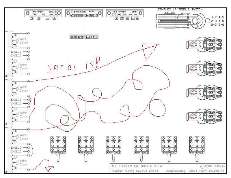 |
|
|
|
Post by sumgai on Sept 21, 2007 12:03:51 GMT -5
Chris,
Ah, I see you finally got your Etch-a-Sketch to save to a file. ;D
sumgai
|
|
|
|
Post by ChrisK on Sept 21, 2007 19:16:24 GMT -5
Yeah, I used my PDA version.   |
|
dmt
Rookie Solder Flinger
Posts: 11
Likes: 0
|
Post by dmt on Sept 21, 2007 20:20:41 GMT -5
LMAO. But seriously. Can I have both schematics? I'll try both. I refuse to debate how horrible it will sound. Give me some options here! I've got a spool of wire and I intend to use it.
|
|
|
|
Post by ChrisK on Sept 22, 2007 10:11:37 GMT -5
guitarnuts2.proboards45.com/index.cgi?board=schem&action=display&thread=1158705194These are good templates to sketch things out on. Just remember that the neck and bridge humbuckers are single wire plus shield unless you do internal mods. Gibson pickups aren't especially high in vintage or resale value due to their current widespread use, but you may want to preserve them. You have an interesting mix in the Gibson pickups since the 490R I believe is an alnico 2 neck pickup and the 498T is a alnico 5 bridge pickup. They should be compatible, but the bridge will be bright and the neck will be warm. Since you wish to primarily experiment, I would recommend a capable, but simplistic wiring scheme for this test bed. Once you find what you're looking for, we all can help with a dedicated wiring scheme. I would recommend against that stage at this point since experimentation is. With that being said, I would recommend the following wiring scheme; guitarnuts2.proboards45.com/index.cgi?board=schem&action=display&thread=1153502513As you look at the schematics, the three toggle switches occupy the area normally used for the 5-way lever switch (use a cheap pickguard and just drill more holes nearby to the slot) can be added to the mods for the three humbuckers. I would use the common drive/normal schematic in the upper left corner to switch the drive structure in unison with a pp pot for volume. Bear in mind that due to the single wire plus shield on the neck humbucker, you will have some noise issues due to the floating shield which must be insulated from any signal ground (it's not a shield here but the other conductor). But this is a test bed anyway, eh? The bridge and neck pickups have the option of parallel/out/series, but the middle only has the option of in/out. and follows the pickup at either end for its structure. If the bridge in in series, the middle can only be in series with the bridge, or out. One can actually relocate any pickup to any position in the design. Since the bridge has a single wire plus shield and has the highest sensed harmonics due to position, I would leave it in the bridge location on the schematic. Since the middle pickup is 2 wire plus shield (and hence EOOPhase reversible), and the middle location on the schematic is the least flexible, I would relocate the middle pickup into the neck on the schematic and the neck into the middle. Just swap the middle and neck mini-toggle switch locations on the pickguard. Since there are 3 pots, I would do the following; Master volume, PP pot for drive structure selection Neck tone, neck tone, pp pot for neck pickup phase reversal (Yeah, I know, but why not.) Bridge tone, bridge tone, pp pot for middle phase reversal With this arrangement, one can change the out of phase structure just by changing the middle pickup (b, m, -n to b, -m, -n) and still experiment with just the middle out of phase. I've found that a middle pickup out of phase with a neck and bridge pickup to be less interesting than the reversal of just the neck or just the bridge in a three pickup combo. I've also found that phasing is much more interesting in a series structure. Remember to use 500K pots, these are humbuckers. One of the tricks that you may want to use is to cut the pickguard's control section off. You will then have a pickup section and a control section. This way, you can easily remove the control section and flip it over for wiring mods without having to remove the strings and entire pickguard (this assumes that one does have enough pickup wire length as things will still be tethered).
|
|
|
|
Post by ChrisK on Sept 22, 2007 11:28:21 GMT -5
|
|
|
|
Post by sumgai on Sept 23, 2007 12:42:43 GMT -5
Chris, I smell a rat! Or as Elmer Fudd would say "Thewe's something vewy scwewy going on hewe." Unless you're Jerry Donahue's long-lost cousin..........  sumgai |
|
|
|
Post by ChrisK on Sept 23, 2007 23:00:00 GMT -5
Well, the Vulcan ( \\// ) would say, "live long and prosper."
Being a Roman Vulcan ( \\|// ),....................
Extrapolation is (did you ever notice that 2 dimensional beingings (such as Elmer) have only.....).
Nd = Dn+1
|
|
|
|
Post by sumgai on Sept 24, 2007 0:56:49 GMT -5
Chris,
OK, that made me spew, +1 for the funny! ;D
sumgai
|
|
|
|
Post by ChrisK on Sept 27, 2007 20:06:00 GMT -5
Dang, it didn't make you pee?  |
|
dmt
Rookie Solder Flinger
Posts: 11
Likes: 0
|
Post by dmt on Oct 4, 2007 1:03:15 GMT -5
Why does that diagram look so complex? Too many options.... I think I will try the series first, and then the parallel. Maybe there is a way to have a switch between the two?
|
|
|
|
Post by ChrisK on Oct 5, 2007 20:44:25 GMT -5
If you mean this drawing: "This is a somewhat complex design that realizes all combinations of three pickups as individual entities. guitarnuts2.proboards45.com/index.cgi?board=schem&action=display&thread=1186634210" It is "complex" on the left schematic side due to this level of complexity being required for a minimal solution of most possible combination of one to three pickups as taught by unk in his Brian May thread in "Schematics" and extrapolated by myself to rotary switches with individual phase or individual internal series parallel selection, and it is "complex" on the right schematic side due to this level of additional complexity being required for a minimal solution set of ALL possible combinations of three pickups as individual entities, with things being; controlled by only three identical switches, laid out in a logical (virtually identical operation of all three switches - in this case two since I diverged in replacing the phase on the bridge pickup with a humbucker with internal series/parallel, touch registered selection (one does not have to look at the switches), with no dead spots except for all off (by design), and being able to fit into a top routed Strat-style body While complex, it is the simplest that such a solution meeting the above features and constraints can be. Internal switch pole count and wiring complexity were allowed to ensure external control (as in switch operation) simplicity and symmetry. If one indeed wishes to realize all possible combinations without switch operation asymmetry or additional push pull pots, and with no undesigned dead spots, complexity is. If you only want a means to put all three pickups in any parallel combination (7 combinations) with additional phase control over one or two pickups, that's actually fairly straightforward. If you want some complexity in switching, but fairly easy wiring, I still recommend my; guitarnuts2.proboards45.com/index.cgi?board=schem&action=display&thread=1153502513 |
|


 )
)


