|
|
Post by mykaguitars on Nov 29, 2007 21:03:13 GMT -5
Thanks for all the great info. I have been a lurker for a while now.
Just wondering if there are any schematics for passive band-pass or band-stop filters for a guitar circuit. I want to have a variable tone control that is flexible enough to pass low or high end frequencies. Or a frequency in between.
I know how to wire a tone control with a capacitor but I imagine passing the high end only is not just a capacitor change.
Thanks for any ideas.
~David
|
|
|
|
Post by sumgai on Nov 29, 2007 23:03:38 GMT -5
David, Hi, and welcome to the NutzHouse! ;D If you search around these forums, you'll see some previous discussions on this topic. Try looking for "bass boost", and don't forget to increase the number of days to look back. It defaults to 7, increase that to something like 500. You can either continue those threads with any questions you might have, or you can come back here for further abuseenlightenment.   HTH sumgai |
|
|
|
Post by ChrisK on Nov 30, 2007 20:43:33 GMT -5
Welcome David, and well,
There are many such things a'foot (or a'net).
Depending on your background and proclivity for themes technical, we can help you with simple circuits all the way thru to running free circuit simulation software (pSpice/5spice) yourself (did I mention that it's free) to "see" things.
|
|
|
|
Post by ranchtooth on Dec 1, 2007 11:13:04 GMT -5
I imagine passing the high end only is not just a capacitor change. It's all a matter of reversing the position of the potentiometer and capacitor. For instance, a common low pass filter is a potentiometer followed by a capacitor running to ground.  A low pass filter, (which we are all so familiar with in our tone controls) is simply the reverse. The capacitor is first and the potentiometer runs to ground. 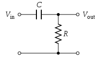 By combining these two filters in one system, you can easily make a variable band pass filter! For both of these, the critical frequency (the frequency at which the circuit attenuates your signal) is given by the good ol' formula Frequency= 1 / (2*Pi * R * C) |
|
|
|
Post by ranchtooth on Dec 1, 2007 11:20:15 GMT -5
|
|
|
|
Post by mykaguitars on Dec 1, 2007 17:54:40 GMT -5
ChrisK I downloaded SwitcherCAD and will look into setting it up for simulations. It looks quite powerful and have seen what you have done with it. Thanks for the tip. I will probably be back with questions but I have enough to get started.
ranchtooth, I appreciate the schematics and link. I think this is exactly what I am looking for.
Thanks for all the help.
~David
|
|


