ironiguana
Rookie Solder Flinger

Posts: 13
Likes: 0
|
Post by ironiguana on Mar 25, 2008 15:11:15 GMT -5
I am working on this single coil wiring design I found called "Mike Richardson's strat wiring". I did not add the phase switch. The schematic leaves out a few things, so I was guessing the missing parts. I seem to have guessed wrong. Positions 1 & 2 with the push-pull up or down work fine. Position 4 with push-pull up gives me nothing (should be bridge and middle) Position 5 with push-pull down gives me nothing (should be bridge only) Position 5 with push-pull up only gives me mid and neck only (should be all 3 in series) At first I thought I hooked up bridge wrong, but it works in positions 3 and 4 with push-pull down and position 3 with push-pull up. I found another drawing that included the phase switches but it was way too confusing. Has anyone tried this Mike Richardson setup before? If so, do you have a full schematic that is clear to read? |
|
|
|
Post by ChrisK on Mar 25, 2008 20:29:29 GMT -5
Aside from the bridge pickup signal ground wire and volume pot wiring, such as............? It's probably mine, and if so, it isn't. It's a wiring diagram and a schematic, as well as a combination chart. It's also complete.  Yes. ! Infers working bridge pickup. All of these involve the neck and/or middle, but only the bridge in position "1" "up". Are you certain that the bridge is working in this mode? (Should be bridge and middle in series.) Infers open bridge pickup. Infers open bridge pickup. (Should be all 3 in parallel.) Infers open bridge pickup. BTW, on the linked sketch, the right-most terminal in each group of five is position "1". When you say that you get "nothing", what does "nothing" mean? A short (the amp is quiet), an open (the amp is noisy as if the guitar end of the cord isn't plugged into anything), or just no sound from the missing pickup (determined by tapping the pickup's magnets with a ferrous object). If you have a digital multi-meter, what resistance readings do you get at the output jack, for each position of the super switch, for each position of the push pull pot (10 readings total)? Make sure that all pots are at the full-on position. If you don't have a digital multi-meter, you should. Some things indicate that the bridge is open in some positions and some things indicate that it's shorted in others. In this case, resistance isn't futile. If you had some pics of the wiring, this would be helpful as well. |
|
|
|
Post by ChrisK on Mar 26, 2008 14:52:28 GMT -5
|
|
ironiguana
Rookie Solder Flinger
Posts: 13
Likes: 0
|
Post by ironiguana on Mar 26, 2008 16:29:39 GMT -5
Aside from the bridge pickup signal ground wire and volume pot wiring, such as............? [glow=red,2,300]I attached bridge - to ground Volume pot middle to jack tip Volume left to ground Volume right to neck tone mid[/glow] It's probably mine, and if so, it isn't. It's a wiring diagram and a schematic, as well as a combination chart. It's also complete. [glow=red,2,300]One of the things that confused me was that there was 3 wires coming from the pickups and the ones I am using only have 2. Which one is + and which one is - ?[/glow] Yes. ! Infers working bridge pickup. All of these involve the neck and/or middle, but only the bridge in position "1" "up". Are you certain that the bridge is working in this mode? [glow=red,2,300]On the diagram, position 1 is neck and position 5 is bridge. Yes bridge is working in position 1 with all 3 in series. It also works in position 3 both series and parallel and in position 4 in parallel.[/glow] (Should be bridge and middle in series.) Infers open bridge pickup. [glow=red,2,300]What does "open bridge pickup" mean? That may be the problem.[/glow] Infers open bridge pickup. (Should be all 3 in parallel.) Infers open bridge pickup. BTW, on the linked sketch, the right-most terminal in each group of five is position "1". When you say that you get "nothing", what does "nothing" mean? A short (the amp is quiet), an open (the amp is noisy as if the guitar end of the cord isn't plugged into anything), or just no sound from the missing pickup (determined by tapping the pickup's magnets with a ferrous object). [glow=red,2,300]Nothing means amp is quiet (when tapping on pickup)[/glow] If you have a digital multi-meter, what resistance readings do you get at the output jack, for each position of the super switch, for each position of the push pull pot (10 readings total)? Make sure that all pots are at the full-on position. If you don't have a digital multi-meter, you should. Some things indicate that the bridge is open in some positions and some things indicate that it's shorted in others. In this case, resistance isn't futile. If you had some pics of the wiring, this would be helpful as well. [glow=red,2,300]I will try to redraw what I have and see if that helps.[/glow] |
|
|
|
Post by ChrisK on Mar 26, 2008 17:24:56 GMT -5
These pickups were DiMarzio Virtual Vintage and there are three wires.
From the left side they are:
R - red, pickup signal output (+ if you wish)
G - green, pickup signal return (- if you wish)
B - bare, pickup frame ground (connected to pot backshells/guitar ground.
Note that (+) and (-) are DC terms and are only representative of the phase of one pickup relative to another. If you interchanged each pickup's red wire with each pickup's green wire, for all three pickups, the guitar would work exactly the same.
It means that the pickup has an internal (or external wiring) open circuit and will have a very high or infinite resistance.
If the bridge pickup was open, any series mode with the bridge pickup would also be an open circuit and would have no output.
Is this the case in all occurances of "nothing", and is the tapping done with a ferrous object (magnetic/iron-based)?
For the fastest resolution, use a multi-meter and measure the resistance at the output jack for each lever and mode switch position. Set the volume at "10".
PP down
1. neck_____
2. n+m_____
3. n+b_____
4, b+m_____
5, bridge_____
PP up
1. n*m*b_____
2. n*m_____
3. n*b_____
4, b*m_____
5, b+m+n_____
|
|
ironiguana
Rookie Solder Flinger
Posts: 13
Likes: 0
|
Post by ironiguana on Mar 27, 2008 18:45:18 GMT -5
PP down
1. neck_____ [glow=red,2,300]6.53[/glow]
2. n+m_____ [glow=red,2,300]3.30[/glow]
3. n+b_____ [[glow=red,2,300]3.59[/glow]
4, b+m_____ [glow=red,2,300]7.79[/glow]
5, bridge_____ [glow=red,2,300]no reading[/glow]
PP up
1. n*m*b_____ [glow=red,2,300]19.89[/glow]
2. n*m_____ [glow=red,2,300]12.79[/glow]
3. n*b_____ [glow=red,2,300]13.98[/glow]
4, b*m_____ [glow=red,2,300]no reading[/glow]
5, b+m+n_____ [glow=red,2,300]3.30[/glow]
|
|
|
|
Post by sumgai on Mar 28, 2008 10:34:38 GMT -5
ii,
I suspect that you've got two problems here.....
The jumper from B+(5) to M+(4) is common to three out of four of your problems. Either it's missing, or there's a bad solder connection on one end (or both!). For my money, the culprit is B+(5).
The remaining problem, Pos 4/up, has only one unique connection that isn't used elsewhere - look closely at M-(4), I'll bet the solder joint is cold.
HTH
sumgai
|
|
ironiguana
Rookie Solder Flinger
Posts: 13
Likes: 0
|
Post by ironiguana on Mar 28, 2008 20:08:50 GMT -5
ii, I suspect that you've got two problems here..... The jumper from B+(5) to M+(4) is common to three out of four of your problems. Either it's missing, or there's a bad solder connection on one end (or both!). For my money, the culprit is B+(5). I put a wire between these 2 and tested with the same results. What is a cold solder joint? I put a wire between m+1 and m-4 and had same results. Do I need to do both at same time? This is my 6th wiring job and I have never had problems like this. Arg! Thanks for your help by the way.. |
|
|
|
Post by ChrisK on Mar 28, 2008 23:11:01 GMT -5
This is my bleary-eyed analysis of the wiring based on the measurements taken "through the nostril". 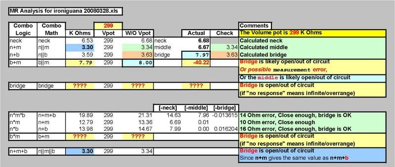 Other than a problematic bridge (and possibly middle) pickup wiring issue (again, assuming that "no response" means infinite or nearly so Ohms (as in open/out of circuit)), I jump to no other additional conclusions other than a possible BAD SUPER SWITCH?   |
|
ironiguana
Rookie Solder Flinger
Posts: 13
Likes: 0
|
Post by ironiguana on Mar 29, 2008 7:33:27 GMT -5
This is my bleary-eyed analysis of the wiring based on the measurements taken "through the nostril". Other than a problematic bridge (and possibly middle) pickup wiring issue (again, assuming that "no response" means infinite or nearly so Ohms (as in open/out of circuit)), I jump to no other additional conclusions other than a possible BAD SUPER SWITCH? That is quite an analysis. I am impressed. I tossed around a bad superswitch but wanted to check other possibilities first. I will rewire the entire thing and if the same thing happens, hopefully stewmac will exchange the switch. Thanks sumgai and chrisk for your help. |
|
ironiguana
Rookie Solder Flinger
Posts: 13
Likes: 0
|
Post by ironiguana on Mar 29, 2008 10:45:30 GMT -5
Since I am starting from scratch again anyway, what would be the easiest, quickest test to see if the super switch is bad?
|
|
|
|
Post by pete12345 on Mar 30, 2008 4:58:27 GMT -5
In all positions, check the resistance between each common terminal and the corresponding ouput terminal. There should be little or no resistance between the common and output, and very high resistance between the common and all non-selected outputs. Do this for each pole.
For example, in position one, common->terminal 1 resistance should be zero, common-> terminal 2-5 should be infinite or at least very high.
Pete
|
|
|
|
Post by ChrisK on Mar 30, 2008 13:09:04 GMT -5
Since you're going back in (to the operating theatre), while you have the patient's "chest open", measure the super switch connectivity for each valid position.
I don't care about all of the other positions, just the ones that should be making contact. For instance, in position "1", verify that each pole is making good contact with the terminals for position "1". The beauty of open frame switches is that one CAN see what is going on.
Also, if you can take a picture of a side view of the wafer and contacts, this would be helpful. In the past, there were super switches with different terminal arrangements (DiMarzio for one).
It's also a lot easier to verify that the switch is broken BEFORE you rewire (maybe it isn't!!!).
It's unlikely that anyone will accept a return on a wired switch. This is why I ALWAYS verify ALL parts before I possibly waste my time on wiring them.
|
|
|
|
Post by ChrisK on Apr 4, 2008 19:51:56 GMT -5
|
|
ironiguana
Rookie Solder Flinger
Posts: 13
Likes: 0
|
Post by ironiguana on Apr 10, 2008 20:43:14 GMT -5
I haven't had a chance to work on this for a while but this is what I did to check the switch. Let me know if this is a good procedure:
I took off all wires except for the poles connected to the pickups.
I checked the side connected to the middle pickup first and touched the multimeter on each side of the switch on both the M+ and M- side in positions 1-5. In each position I got a reading of 6.73 which I believe is the power of the middle pickup.
I then went to the other side. I checked the neck pole first touching one side of the multimeter to the poles in position 1-5 (-)and the other side to the middle position neck tone (+). I got a consistant reading on all poles. I checked the bridge pole in positions 1-5 (+) with the other end of the multimeter where (-) was grounded. I got consistant readings across all of those poles also.
Is this a good switch? It seems to have made connections on all positions. Is this a good way to check a switch or not? Thanks.
|
|
|
|
Post by Mike Richardson on Apr 15, 2008 16:28:05 GMT -5
I dunno. It worked when I did it.
|
|
|
|
Post by ChrisK on Apr 15, 2008 19:44:29 GMT -5
I dunno, what consistency were the readings?  |
|
ironiguana
Rookie Solder Flinger
Posts: 13
Likes: 0
|
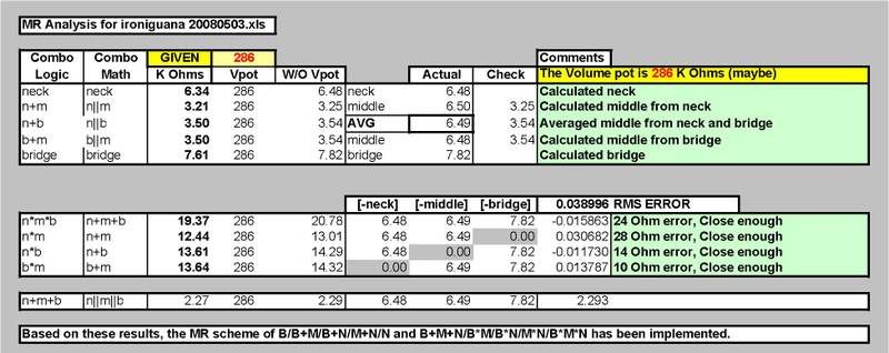
Post by ironiguana on May 3, 2008 11:38:53 GMT -5
I rewired with these readings:
push pull down:
1. 6.34
2. 3.21
3. 3.5
4. 3.5
5. 7.61
push pull up
1. 19.37
2. 12.44
3. 13.61
4. 13.64
5. 2.27
Do these readings look correct?
|
|
|
|
Post by ChrisK on May 3, 2008 13:28:23 GMT -5
|
|
ironiguana
Rookie Solder Flinger
Posts: 13
Likes: 0
|
Post by ironiguana on May 3, 2008 16:56:29 GMT -5
Cool. Thanks.
|
|