andywelsh
Apprentice Shielder

Posts: 35
Likes: 0
|
Post by andywelsh on Apr 1, 2008 11:08:07 GMT -5
I'm building an HSH strat and am planning on using a 4p6t rotary for each HB as found in Brosnac's "Guitar Electronics for Musicians".
1st Question: Does the single coil need to be RW/RP? I think probably not, but I'm not sure.
The next problem is the pickup selection: I prefer a blade switch and I'd like almost the same combinations as in Mike Richardson's schematic with a couple of exceptions, specifically - vol pot down: the 5 normal selections; vol pot up: all 3 series, n & m series, n & b series or parallel (whichever is easier, but I suppose parallel makes most sense), m & b series, all 3 parallel.
I'd also like a phase switch for the neck pickup via a pull switch on the neck tone pot.
Furthermore I'd like the "middle" tone to control middle and bridge tone. (like the no-load pot on the new strats).
Does anyone have a wiring diagram for this, please? Its the pickup selector switch I'm having most difficulty working out.
Thanks a bundle
Andy
|
|
|
|
Post by ChrisK on Apr 1, 2008 17:46:53 GMT -5
Why, not all of the 6 positions are useful? Two side-by-side humbucker coils in parallel out of phase are usually useless and two in series out of phase are nearly so. That being said, the other four are useful. With what? By virtue of being able to select either coil on both humbuckers, the middle will be hum canceling with two of them (one per humbucker) and not with the other two of them. You get to choose, which drives the selection of the middle pickup's phasing/polarity. Here's the original Mike Richardson Strat design (well, after the super switch was changed away from the DiMarzio one).  Here's one that does M and B * M + N instead of B + M and B * M. I haven't checked to see if it does B * (M + N) or (B * M) + N (Q.E.D.). 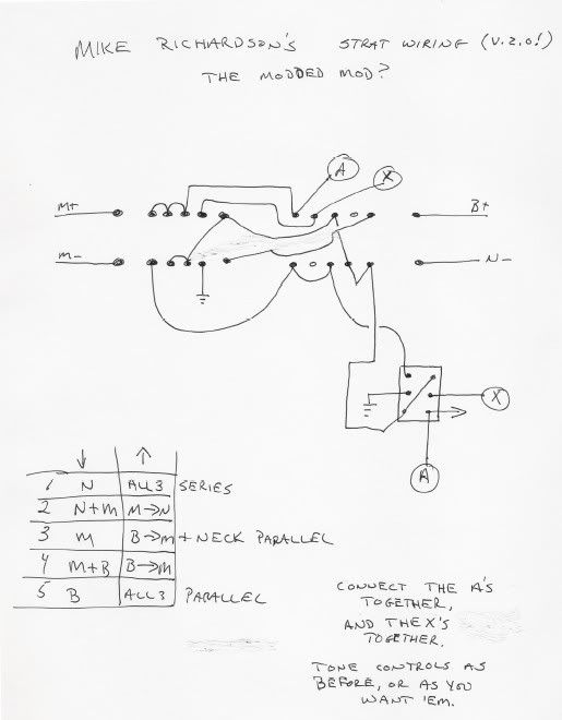 Good choice. This switch goes between the neck's 4P6T rotary and the pickup selector. Huh? Don't you already have a neck tone pot? As far as having a tone control across both the middle and bridge pickups, this gets a tad complicated since there are no spare poles on the super switch and it needs to be across both a parallel structure and a series structure. Furthermore, what does it mean when all three pickups are in parallel? In series? Which tone pot has effect? No, but the ones that I posted go a long way toward the solution. The phasing for the one pickup is simple since it's between the 4P6T on the neck and the super switch. The only thing of a complex nature will be the combined ?bridge? and middle tone. |
|
andywelsh
Apprentice Shielder
Posts: 35
Likes: 0
|
Post by andywelsh on Apr 2, 2008 5:57:29 GMT -5
Thanks ChrisK for your reply and the comments about the "Useless" tones - saves me trying 'em out! Ditto about the RW/RP and the tone controls (Sorry - I meant to say middle and bridge as you surmised)
Re the schematics: does B- go to ground? (I don't see it in the diagram)
The second option seems closer to what I'm trying to achieve - it just leaves the question of the tone controls (e.g. is it possible to wire them "normally"? duh, how?) and the bridge/neck pickup selection.
Thanks again, you've been a great help. Sorry I'm a bit thick!
Andy
|
|
|
|
Post by ChrisK on Apr 2, 2008 18:15:13 GMT -5
Yep, it's one of those obvious things (obvious only to folk that should know better than to leave it out). We draw diagrams this way so others are confused and have to frequent boards like this one, thereby giving some glimmer of necessity to those so socially obtuse that they spend their time designing guitar wiring (with critical information purposely left off). I did an analysis of the MR2 design and found the following ("+" is parallel and "*" is series): Mode DOWN 1. Neck (B * M shorted) [1] 2. Neck + Middle (B open) [1/2] 3. Middle (N open/hanging, B shorted) [1] 4. Bridge + Middle (N open/hanging) [1/2] 5. Bridge (M + N hanging, but M- and N- not connected elsewhere) [1] Mode UP 1. B * M * N [3] 2. M * N (B open) [2] 3. (B * M) + N [2/3] 4. B * M (N open/hanging) [2] 5. B + M + N [1/3] #3 ((B * M) + N) is not a bad combo. I think that you'd like it, it's sort of sideways between B * M and B + N. The [numbers] are the relative inductance of nominal pickups (with a "value" of identity) in that combination. For instance, 2 in series will have a nominal value/ratio of twice that of just one. Conversely, 2 in parallel will have a nominal value/ratio of 1/2 that of just one. The lower the ratio, the brighter the sound. I don't see an obvious place for connecting the middle/bridge tone circuit. When I do a MR scheme, I put one tone directly across the neck pickup and one directly across the bridge. (But then, I've never used a design with just the middle as an option.  ) |
|
andywelsh
Apprentice Shielder
Posts: 35
Likes: 0
|
Post by andywelsh on Apr 3, 2008 6:58:52 GMT -5
Hi ChrisK - Thanks again; I'm really glad I found this site before I did any complicated wiring! Its the first time I've tried anything other than just replacing pickups with maybe a series/parallel switch.
So... 1) the reason why I settled on the 4p6t switch for the pickups is because I couldn't find a 4p4t toggle or rotary and if the options are there why not wire them up - its not obligatory to actually use them!? So, can you recommend a supplier that might have a 4p4t switch please?
2) Upon reflection, bridge & neck is probably "better" than middle alone. So MR1 is probably the way to go. Having said that I'm intrigued by b*m+n so maybe I'll give that a go another time.
3) Speaking of "MR" - I came across the full blown schematic including phase switches etc (thread #1153172741) - phew! It seems to do everything except b*m+n! However, looking at that diagram and the ones you posted in response to my query I see a couple of anomalies. I'm not sure whether to query it here or on the thread itself, but here goes (sorry if its in the wrong place):
On the wiring for the superswitch at the bottom there are x's and o's for non-connections/connections. However on the "M-" pole there is an "o" for position D with nothing connected. Is this free, or connected to ground (as in the "pencil sketch" you posted for me)? (I'm sorry, but I can't work it out from the top half!!)
Furthermore, there's a stray "x" at the bottom which I have no idea what it refers to.
Finally, I'm assuming the wire from the Vol pot that ends in a triangle is the earth wire to either the tremolo claw or the screening. But which?
Thanks again so very much.
Andy
|
|
|
|
Post by ChrisK on Apr 3, 2008 19:06:39 GMT -5
No, it will require two decks anyway, so I'd use a 4P6T (although one can get a 4P6T that could be pinned to 4P4T search.digikey.com/scripts/DkSearch/dksus.dll?Detail?name=GH7104-ND ) and it's real small. lgrws01.grayhill.com/web/images/ProductImages/71rotary.pdf Yeah, that would be me. Yep. It goes to ground. If you look at the top schematic, the four arrows are the pole commons and the terminals under "A to E" are the position terminals for each pole. And, the "X" is a marker for position "D" (which has a missing connection for M-). I'm impressed with your attention to detail. No one had noticed this over the year and a half that this design has been posted. This means that no one prior to you has caught on to this, or, no one has built it (well, one person did) other than me from this diagram. Sigh. I'm also depressed. Now that attention has been drawn to this design anew, I changed the description of the switch positions in the post from "1" thru "5" to "A" thru "E". No one asked about this either. |
|
|
|
Post by sumgai on Apr 4, 2008 13:01:47 GMT -5
Chris, Well, sum of us have figured out your brain-waves, and we're able to follow your often incredible leaps of logic. There's no magic here folks, move along please. sumgai |
|
|
|
Post by ChrisK on Apr 4, 2008 19:46:50 GMT -5
Yes.
It is signal ground. It depends on where one is connecting "things" in one's overall wiring/shielding/isolation scheme.
Help needed in "Shielding the Beast" aisle please."
|
|
|
|
Post by sumgai on Apr 5, 2008 3:41:19 GMT -5
One each HELP, coming right up!  andy, try this on for size. Bill has done an incredible job of laying bare the mysteries of how to connect everything up, I hope you'll agree. ssstonelover's QtB schematics, with variantsHTH sumgai |
|
andywelsh
Apprentice Shielder
Posts: 35
Likes: 0
|
Post by andywelsh on Apr 5, 2008 11:24:19 GMT -5
Wow! You guys certainly are thorough!!! Thanks for all your help - all I have to do now is actually wire the thing!!!!
I'll admit I'm still a little confused when amendments have been made to the posts, but I'm sure reading it through a few times with a cup of tea in hand (I'm English you see) will help. There's also phrases like "star grounding" I haven't come across before, but I guess I'm learning and its better to do it on paper than by frying so thanks again.
Cheers
Andy
|
|
|
|
Post by sumgai on Apr 5, 2008 12:07:30 GMT -5
andy, Hey, we won't hold that against you! Why, some of our best members are from Great Britain! ;D You can learn more about star grounding, particularly as it relates to guitar wiring, here: "Quieting the Beast". Bring that up in your browser, and also open up another session with the above link (QtB schematics), and I think you'll get a pretty good understanding of what's supposed to go on. ;D HTH sumgai |
|
andywelsh
Apprentice Shielder
Posts: 35
Likes: 0
|
Post by andywelsh on Apr 5, 2008 13:55:55 GMT -5
Thanks again & what speed!
Just one VERY small niggle.... when I tried to print "QTB w/variants" the bottom half of the image got lost so I had to copy and paste into Word and reduce the image size. Its a hard life and if thats my only problem things aren't too bad!!!
Toodaloo
Andy
|
|
|
|
Post by sumgai on Apr 6, 2008 1:16:09 GMT -5
andy, The standard joke amongst programmers of old refers to the fact that OS/2 couldn't print for love nor money until Version 2. To show our agemad skilz, we simply substitute the nefarious product currently suffering our disdain, like this: "We're waiting for Web Version 2.0..... that's the one that'll finally print!"  ;D sumgai |
|
andywelsh
Apprentice Shielder
Posts: 35
Likes: 0
|
Post by andywelsh on Apr 8, 2008 4:28:58 GMT -5
Hi again
I just wanted to confirm I understood this right....:
If I install 4 conductor + bare wire humbuckers (or indeed 2 wire + braid single coils) I still connect the bare(/braid) wire(s) to the back of the vol pot and NOT the star ground point.
Should I put sleeving/insulation over these wires?
Furthermore, does it matter where in the control cavity the new capacitor and the star ground point go? Obviously one wants to keep the connections as short as practicable.
Thanks again. Cheers.
Andy
|
|
|
|
Post by pete12345 on Apr 8, 2008 5:08:50 GMT -5
'If I install 4 conductor + bare wire humbuckers (or indeed 2 wire + braid single coils) I still connect the bare(/braid) wire(s) to the back of the vol pot and NOT the star ground point.'
Yep. All signal returns go to the star ground, non-signal-carrying shields go to the back of a pot.
'Should I put sleeving/insulation over these wires?'
It wouldn't hurt to. All it takes is one stray strand in the wrong place to mess up your wiring
'Furthermore, does it matter where in the control cavity the new capacitor and the star ground point go? Obviously one wants to keep the connections as short as practicable.'
Doesn't really matter. As long as the connections are the same, you can put it where you like- or perhaps more likely, wherever it will fit.
Pete
|
|
|
|
Post by sumgai on Apr 8, 2008 11:33:06 GMT -5
If I install 4 conductor + bare wire humbuckers (or indeed 2 wire + braid single coils) I still connect the bare(/braid) wire(s) to the back of the vol pot and NOT the star ground point.
Yep. All signal returns go to the star ground, non-signal-carrying shields go to the back of a pot.Not quite. (pete, I think this is the first time I've had to say anything like this for you. Sorry 'bout that.  ) Pickup signal returns should go wherever they are destined within the switching scheme that you've chosen - that isn't always a ground point, star or otherwise. Actually, you over-answered his question, he didn't ask about signal returns, only about the braided shielding. But I make this point specifically because the referenced drawings don't include any humbucker versions at all (Note to self: need to fix that!), and while andy is probably cognizant of what's going on, the next reader who comes along might not make that distinction. But the rest of your answer was spot on, as usual for you. ;D andy, HTH! sumgai |
|
andywelsh
Apprentice Shielder
Posts: 35
Likes: 0
|
Post by andywelsh on Apr 9, 2008 8:17:47 GMT -5
Thanks for all the help. I thought I had it, but I think what's confusing me is trying to link the Mike Richardson schematic with a star grounding scheme.
So, trying to summarise everything:
I'm building an HSH strat with a 4p6t rotary switch on each humbucker connected to the "Mike Richardson with Phase" scheme.
I wire the rotary switches according to Brosnac's book which leaves one hot and one ground coming from each rotary switch heading to the phase push/pull switches on the appropriate tone controls.
The middle pickup signal wires go to the pup selecter switch which is wired as in the MR diagram but with an extra wire going from pos D on the M- pole to the "mode" switch on the vol pot. - or can that go direct to ground?
While all this is going on, the bare wires are connected to the back of the various pots as in Mike R's schematic.
Up to now I've just amalgamated (like "modules") 2 wiring diagrams. What I don't quite get is how to amend this monster for star grounding.
Sumgai, I'm flattered by your opinion of my knowledge, but as you can see I don't have the same confidence in my abilities!
When this is all done, I should have a very versatile yet simple to understand switching arrangement/guitar which has a great complement of both humbucking and single coil sounds!
Waiting in anticipation....
Andy
|
|
|
|
Post by sumgai on Apr 9, 2008 12:12:59 GMT -5
andy, First, we've been shooting in the dark, most of us...... we need to see what Brosnac is talking about. While it's not exactly "correct" (don't use the "L" word here!), could you scan that image into your 'puter, and post it here for us to see, please? I was OK with everything until you said 'one 4P6T per pickup', that threw me for a loop!  But even without that, I'm wondering here.... what benefit will you derive from connecting Position D (on M-) to the mode switch? This is yet another reason to have a picture of all the parts and pieces (the modules, good choice of words), we don't wanna bless something that we haven't even seen, lest it go up in smoke before your very eyes!  HTH sumgai |
|
|
|
Post by ChrisK on Apr 9, 2008 19:59:56 GMT -5
Yes, the Brosnac module. Let's agree that the output wires from these modules are the module signal output and module signal return. We can also call them "Pickup +" and "Pickup -", but this is confusing. Let us NOT call them hot and ground, which they are not (perchance yet), and may well never be. Just as the Brosnac modules are modules, the MR wiring scheme is just another module in the overall scheme. The final module (the wrapper if you will) is the star grounding and shielding scheme. In this module, and only in this module, is anything connected to ground in the sense of an electrical ground connection to the, uh, ground. At this level/wrapper, the master signal return point and signal output connect to the real world and exit the body. It goes to the internal MR module signal return point. The bare shield leads from the pickups can be connected to the pot back shells (which presumably are all connected common). If the isolation cap is used, these will be isolated along with the back shells and strings. As we all do! This monster needs to be wrapped in the star grounding scheme. If a star grounding and isolation scheme is to be used, there are three circuits of interest that need to be AC connected (as in passing AC signals generated BY THE PICKUPS). A. One is the internal signal return point (the internal signal "ground" if one must) that is the reference point for signals. B. The second is the external system ground point, usually the cable shield. C. The third are the exposed conductive (note that I didn't just say metal) surfaces. One wants as little as touchable possible to be directly connected to said "reality". Unfortunately, the Strat jack plate is still an exposed issue. What really needs to be done is to use an isolated ground jack (perhaps like the plastic ones on cheap amps) and "free" the jack plate. The point of the big capacitor is to glean some galvanic isolation from the amp and mains distribution system to the/any exposed surfaces. In essence, there is a safety cap that performs this isolation of the exposed surfaces (C) from the internal signal return point (A) and the cable return/shield (B), which are connected common. The internal circuitry is still galvanically (DC) connected to the cable/amp For a standard, non-isolated wiring scheme, all three of these are connected common (A, B, C). I don't use ground isolation schemes in-body, but use RF for the best, safest "out-of-body" experience possible. Only lightning jumps that gap. So, you have two Brosnac modules feeding into the MR module, which feeds into the star grounding/isolation module that is connected to the cable signal output and signal return, and via the isolation cap, to the exposed conductive surfaces (except fer the dang jack plate). |
|
andywelsh
Apprentice Shielder
Posts: 35
Likes: 0
|
Post by andywelsh on Apr 10, 2008 10:58:38 GMT -5
Firstly - thanks again ChrisK. To misquote Henry Higgins "I do believe I've got it!"
Secondly, Sumgai - thanks also. I was told that Donald Brosnac's Guitar Electronics for Musicians was the pickup wiring Bible..... but then I found this website!!
I will post scans of the relevant pages! I hope they help explain what I'm up to (or hope to get up to!!).
|
|
andywelsh
Apprentice Shielder
Posts: 35
Likes: 0
|
Post by andywelsh on Apr 11, 2008 7:38:08 GMT -5
So... here's the scans: 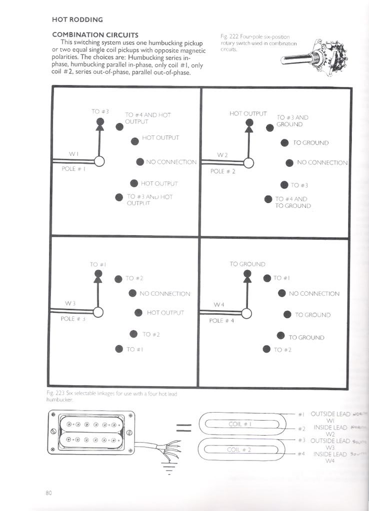 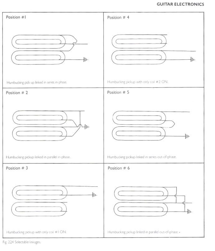 Cheers Andy |
|
|
|
Post by sumgai on Apr 11, 2008 14:33:16 GMT -5
andy, I had to stop and think for a few moments, in order to puzzle out what Brosnac was saying/doing. It would appear that his drawing is overly busy, but he's really just telling the reader to build a couple of short jumpers between some of the terminals, in order to make it easier to build, I presume. I could quibble about his labeling, but it's too minor, and we do all tend to think slightly differently anyways, so in truth, as long as I got the message, then his labels can't be all that wrong, eh? For hooking up a pair of these, with a phase switch, with an additional Neck On switch, and then stuffing them into a rig with a 5-way Superswitch, that's ambitious, to say the least! Good luck, and take plenty of pictures! Post them when you're done, and keep 'em for future reference, just in case, you know. Hmmm, just re-read your initial post..... do you still need a schematic, or are you comfortable with what you've got now? sumgai |
|
andywelsh
Apprentice Shielder
Posts: 35
Likes: 0
|
Post by andywelsh on Apr 12, 2008 5:36:44 GMT -5
Hi Sumgai Glad you get it. It will unfortunately be a while before I finish this - cos as you say its ambitious, but I will take pics as requested! After discussion on this thread, my needs have changed from the original post! I'm now mixing the rotary switch on each humbucker idea (keeping the HSH format for the moment) with the Mike Richardson with phase idea since I can't do what I originally wanted with the tone pots etc. I also realise I need to shield it all properly. I think I have it sussed, but a schematic/real world wiring diagram would be great please because you can never have too much help when doing something like this. It would also confirm/disprove whether I have/have not understood the star grounding scheme!!! Thanks for all the time you've taken with this. Cheers Andy |
|
|
|
Post by sumgai on Apr 13, 2008 12:42:59 GMT -5
andy,
Since you have to take a short break, I'll do the same. When you get back to the grindstone, I should have a schematic ready for you. Lord willing, and the wife don't find out! ;D
sumgai
|
|
andywelsh
Apprentice Shielder
Posts: 35
Likes: 0
|
Post by andywelsh on Apr 18, 2008 6:34:26 GMT -5
Hi - me again.
So, I've had a blitz on ebay and now have the pickups: Seymour Duncan L'il 59 (neck), and JBJr (bridge) with a Fender Tex Mex RW/RP single coil for the middle. HTH with the wiring diag.
As the humbuckers are strat-sized minis, do you know if there will be much difference in sound between each coil when split? The reason I wanted to have the option of choosing which HB coil was active was because PRS use different coils in their switching systems. However, if there is going to be no real discernable difference, I might as well simplify things and scrap the rotaries and just use a pair of on/on/on dpdt's for series/split/parallel. This would be a lot easier to fit in the space too!!
Your thoughts would be much appreciated.
I'm also thinking of forgetting the star grounding as you & ChrisK don't usually use it and 'just' shielding the guitar properly. What I'm looking for is simplicity with versatility. What do you think?
Thanks again
Andy
|
|
|
|
Post by sumgai on Apr 18, 2008 16:38:16 GMT -5
andy, Simplicity is! However, if you don't use the "big boy" scheme, how will know if your not missing out on the all-time KILLER tone? In short, you have the goodies in hand (or on your bench), you might as well use 'em. If you don't like it (too busy (hard to use), or it's overkill (only use one or two tones)), then you can pull out the unwanted stuff, and insert smaller/simpler controls - after you've made your tests/experiments/midnight bombings over the local watering hole. If the pickguard is no longer viable, a new one can be had for small change, considering what you've learned.  As for the two coils in a standard Strat-sized Hb, I couldn't tell you if they're close in tone, or otherwise..... sorry. HTH sumgai |
|
|
|
Post by newey on Apr 18, 2008 21:44:26 GMT -5
Andy-
FWIW, I did a coil split on a SC sized HB and found very little tonal difference. Different pickups, different guitar, YMMV, all the usual disclaimers apply.
But I wouldn't bother to do it again.
|
|
andywelsh
Apprentice Shielder
Posts: 35
Likes: 0
|
Post by andywelsh on Apr 20, 2008 11:40:26 GMT -5
Cooee
Thanks for the replies. While I think simplicity is best and Newey's comments notwithstanding, I think I will try out the all singing all dancing version. At least then I'll know I've at least tried it all!
Having said that, the more I think about it I think the star grounding is overkill so I will keep things more traditional in that area.
So, Sumgai, if your offer of a schematic and a real world wiring diagram is still open I will take you up on it please.
Will the tex mex pu being braidless make a difference? Or maybe I should go the whole hog and put another humbucker and rotary in! ;D Only kidding - I think I'll stay with an HSH - for now!!
Cheers
Andy
|
|
|
|
Post by sumgai on Jun 9, 2008 18:57:58 GMT -5
andy, Per a recent email, here's what I think you want...... strong emphasis on the "I think" portion. Discussion follows the image.  Note a couple of things: I don't do "wiring diagrams", except where I'm modifying someone else's product, and in a very simple manner. It's simply not on my menu of available options, sorry.  Perhaps one of our other fine members here can translate my anally-orthagonal chicken scratches?  I've translated the Brosnac Module into a true schematic, that's what you see on the left side. See those two right-pointing arrows, with a short break in the middle of the lines? That denotes that an exact copy is to be inserted where the arrows are duplicated. All that changes is the label, in this case that would be the Neck and Bridge pickup labels. If I didn't do this, the diagram would be monstrously large for a screen, and wouldn't really give you any more details anyway. As ChrisK would say "Clones are." The main portion of the circuit is a proper schematic rendition of the Mike Richards v. 2.0 mod, as presented by ChrisK in his first reply, on Page 1 of this thread/topic. There's a Phase switch for the Neck pup, as well as a Neck On switch. I want to caution you that if you turn on the Neck pickup while the Series knob is pulled up on your push-pull, you're going to see some "interesting" things happening...... In Position 1, you'll lose all signal from Middle and Bridge pickups. The reason is simple: the Neck - signal comes from the Middle + lead, right? And the Middle - signal is grounded, eh? So, by engaging the Neck On switch, you'll be sending both the + and - leads of the Middle pickup to the same point, i.e. ground......... not a good thing, sound-wise, but also not harmful in any way. The same thing happens, for the same reason, in Position 2. However, in Positions 3 and 5, there's no effect, the Neck pup is already on in Parallel with the other two pickups. and in Position 4, you're duplicating the combination found under Position 3. I just wanted you to be aware of the consequences when you suffer a Senior Moment. ;D You are free to reverse the labels between the Neck and Bridge pickups, should you feel the urge. HTH sumgai |
|
andywelsh
Apprentice Shielder
Posts: 35
Likes: 0
|
Post by andywelsh on Jun 10, 2008 10:43:12 GMT -5
Hiya Thanks for all your hard work. Sadly, your remarks raise some questions...  I think maybe some things have got lost in translation from what I originally asked for, and what, after discussion on the thread, I actually decided on. So here goes: A HSH configuration with both humbuckers each having a 6 pos rotary for a) both coils series in phase b) both coils parallel in phase c) coil 1 d) coil 2 e) both coils series out of phase (soup!) and f) both coils parallel out of phase (poop!). So far so good? Feed this into the Mike Richardson idea to give the following: Series/parallel push/pull on the vol knob; phase push/pulls on the tone controls to affect each humbucker and to give the following combos with the 5 way lever switch: Vol switch down: a)neck b) neck + middle parallel c) neck + bridge parallel d) middle + bridge parallel e) bridge Vol switch up: a) all 3 parallel b) neck*middle series c) neck*bridge series d) middle*bridge series e) all 3 series (Obviously activating the tone push/pulls would put the neck and bridge in/out of phase as appropriate.) The reason I've gone through all this is because I don't see any duplications in settings as you describe in your remarks. Furthermore, if I'm looking for all 3 in series it doesn't make sense to have the signal drop out from middle and bridge! Have I missed something? Finally, just for info, I'll be using a Seymour Duncan Lil '59 (Neck), Fender Tex Mex RW/RP (Middle) and a Seymour Duncan JBjr (Bridge). Hope you can help - you're my only hope Obi Wan - er.... sorry about that - brain overload!!! Regards Andy ( Edited by sumgai to make the table of pickup combinations easier to read and discern.) |
|


 )
)


 ;D
;D

 )
)


