kramer1309
Rookie Solder Flinger

Posts: 20
Likes: 0
|
Post by kramer1309 on Apr 27, 2008 6:18:50 GMT -5
Hello I own a Kramer Strker FR424SM from '06. I was looking at doing something interesting with the wiring and decided to first completely understand what is already going on with the stock wiring. I havent found out the values of the pots and the cap that were already in there. So opened up the back cover and drew a wiring diagram. What i would like some help with is first of all confirming whether this is the correct diagram or not (or if i have messed up somewhere and have something that will result in no output). First, pics of the guts :  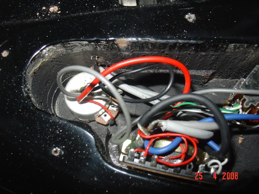 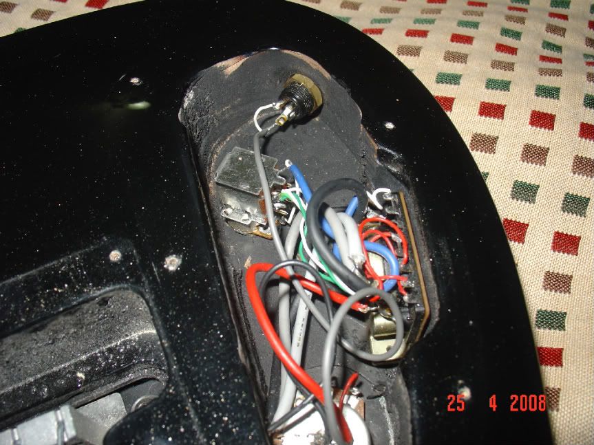 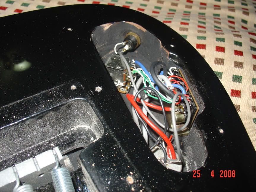  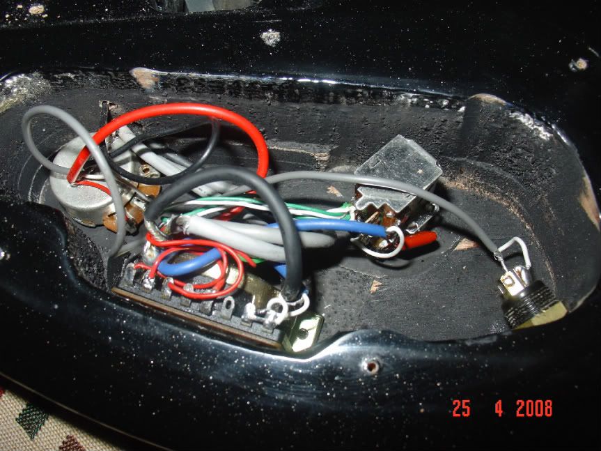 Pic of the guitar:   Wiring diagram of the pickups: -The DualRail :  -The QuadRail :  The Diagram i drew up:  The naked wire is drawn in a silver pen that looks grey at some places and shines at others. The naked wire is drawn in a silver pen that looks grey at some places and shines at others.The white wires are drawn with a blue pen. The thick blocks are wiring cases which have more than one wire in them. The 5 way switch has the 8 connectors that i drew longer in line and the other two (the two shorter ones at the ends of the diagram) are on a slightly lower level... i didnt understand this.The one closer to the neck has all the black and naked wires from the pickups as well as the naked wire from the body of the volume pot wired to it in a large mass of solder. Can someone please help me with the 5 way switch and how exactly it is wired - What is going on within the switch? (its got 5 positions : Neck :: Neck+Middle :: Middle :: Middle+Bridge :: Bridge) So, any confirmations/help/info about the pot and cap values ?? Thanks |
|
|
|
Post by newey on Apr 27, 2008 8:46:21 GMT -5
Kramer- Hello and Welcome! These are the common lugs, one of which is being used as a common ground, implementing the "big blob of solder" technique.  For more info on the functioning of this switch, check the schematics sub-board above and go to the "modules" thread. Also look at ChrisK's "Off-shore lever switches" post. As far as the caps and pot values, if you can't find a spec sheet from Kramer somewhere on that Web thingy, you'll need a multimeter. This technique avoids tearing things up to figure stuff out: Brain scanBTW, your posting is very detailed, but what does the push-pull pot do in the scheme of things? |
|
|
|
Post by papacueball on Apr 27, 2008 9:22:47 GMT -5
I think the push-pull splits all three pickups, giving you the coil(s) closest to the neck.
|
|
kramer1309
Rookie Solder Flinger
Posts: 20
Likes: 0
|
Post by kramer1309 on Apr 27, 2008 10:01:46 GMT -5
Yeah the push/pull works on all three pups but im not sure whether it splits or taps - could someone please have a look at the wiring diagram i made (last pic) and tell me - the middle pickup's cleans sounds amazing.
Also, i don't know which coils the push pull engages all three pickups (which are all essentially 3 humbuckers) - any ideas?
Thanks
|
|
|
|
Post by ashcatlt on Apr 27, 2008 10:54:14 GMT -5
Newey, the short lugs in his diagram are actually the ground lugs for the switch itself, being used almost like a star ground. Commons are in the middle from what I can tell. The push-pull shorts out one coil (the one with the black wire coming out of it) on each pickup. That would be a split. I'm just a little confused how it works out in the non-split position. Say you've got the 5-way in bridge position. Are you going to get (NS+MS+BS)>BN?  |
|
|
|
Post by papacueball on Apr 27, 2008 11:20:02 GMT -5
|
|
|
|
Post by papacueball on Apr 27, 2008 11:58:43 GMT -5
I'm just a little confused how it works out in the non-split position. Say you've got the 5-way in bridge position. Are you going to get (NS+MS+BS)>BN? That's what it looks like to me. Looks like that position leaves out the tone control as well. |
|
kramer1309
Rookie Solder Flinger
Posts: 20
Likes: 0
|
Post by kramer1309 on Apr 27, 2008 12:28:24 GMT -5
I'm just a little confused how it works out in the non-split position. Say you've got the 5-way in bridge position. Are you going to get (NS+MS+BS)>BN? That's what it looks like to me. Looks like that position leaves out the tone control as well. In the last position, the bridge pickup only is engaged and the tone pot does work there... I looked at Seymour Duncan's plethora of wiring diags and the one with a HSH+1Vol+1Tone+push/pull+5Way looks nearly exactly like this (other than color coding; in my diagram - Afaik - Red=Hot, Green&White=For splitting, Bare&Black=Ground) and for the fact that my middle pickup is also a humbucker (sortof) - So the diagram is correct & it works So, i still havent found the post about how the 5 way works - i mean i get that the outer (shorter) lugs are ground and middle two are common (red wire from volume pot) - i need to know how the 5 way works from the inside (w/o opening it ) - as in how it makes the combinations? btw, Thanks everyone, you've been really helpful |
|
kramer1309
Rookie Solder Flinger
Posts: 20
Likes: 0
|
Post by kramer1309 on Apr 27, 2008 12:32:53 GMT -5
The wiring diagram of the pickup from the official website shows that the green and white are on the inner two rails while the black and red are on the outer coils of the 4 coil double bucker. (posted in first post) So im not sure what you said is correct unless i understood it incorrectly |
|
|
|
Post by newey on Apr 27, 2008 15:15:09 GMT -5
Kramer: Sorry for not giving you the link to the switch info this morning, it was early and I was caffeine-deficient at the time. Look here: Electronics TemplatesAnd Here: Offshore lever switchesYour switch is probably similar to one of these, although I believe Ash is right, the commons are in the middle and the end lugs are for grounding. Most of these lever switches don't have the separate grounding lugs, so far as I have seen. While it is certainly worthwhile to understand how your guitar is wired, you said you were contemplating doing "something interesting with the wiring". Did you have anything specific in mind? |
|
kramer1309
Rookie Solder Flinger
Posts: 20
Likes: 0
|
Post by kramer1309 on Apr 27, 2008 15:48:59 GMT -5
Kramer: Sorry for not giving you the link to the switch info this morning, it was early and I was caffeine-deficient at the time. Look here: Electronics TemplatesAnd Here: Offshore lever switchesYour switch is probably similar to one of these, although I believe Ash is right, the commons are in the middle and the end lugs are for grounding. Most of these lever switches don't have the separate grounding lugs, so far as I have seen. While it is certainly worthwhile to understand how your guitar is wired, you said you were contemplating doing "something interesting with the wiring". Did you have anything specific in mind? That'll probably be later - but i wanted to take the 5 way out and put three mini toggle on/off/on instead for each pickup with the switch making it go on/of/split (not sure whether i need SPDT or DPDT for these) and use a series parallel for the bridge with the push pull... but that'll take sometime coz i gotta get into college rite now... thanks |
|
|
|
Post by ashcatlt on Apr 29, 2008 12:19:00 GMT -5
I guess we answered the OP's questions. Now how about mine?
Can somebody tell me how this scheme manages to select any one given pickup when the pickups aren't split?
I used the bridge as an example above, but the same holds true for any other position of the 5-way. Seems to me like the S coil of each pickup (or the S pair for the 4 coil bridge) are in parallel with each other and then running in series through every other pickup.
Maybe the designer decided that the extra coils were negligible in comparison to any full humbucker that might be selected. Fine except, again, the bridge is a 4 coil double humbucker, with the split point between two pairs, which would leave a full humbucker in mix.
So, am I missing something?
|
|
kramer1309
Rookie Solder Flinger
Posts: 20
Likes: 0
|
Post by kramer1309 on Apr 29, 2008 13:05:39 GMT -5
Well , the red wire is hot , black is ground - not the same as most popular manufacturers.
i still havent got how the switch makes the combinations inside it.
^^When the pups are'nt split this is what happens (well i can hear it - not explain it through the diag as i havent understood the switch - yeah i saw the links but still nothing) :
Pos1 (closest to neck)
All 4 neck coils
Pos2
4 Neck coils + 2 Middle coils
Pos3
2Middle coils
Pos4
2 Middle coils + 4 Bridge coils
Pos5
4 Bridge coils
|
|
|
|
Post by ashcatlt on Apr 29, 2008 14:56:49 GMT -5
And how did you determine that? That's what one would expect from standard strat wiring, but is not what I'm seeing happen with that split switch gathering the "middle" wires all in one place and connecting everybody to everybody else.
I think the problem you're having with the switch is that, while it has 5 physical positions, it only actually has 3 electrical ones. In position 1, 3, or 5, it connects pin 1, 2, or 3 to the common lug on each half of the switch. Positions 2 and 4 simply short or connect both adjacent pins (1+3, or 3+5).
The switch has 2 poles. Doesn't really matter which end you start counting from. Either way it should be like so:
pole1(1-2-3-c)pole2(c-1-2-3)
The 2 lugs which are not in line with these 8 are not involved in the switching aparattus at all. They don't ever connect to the lugs on the switch (unless you do it via a wire). They are connected to the metal frame of the switch and are generally grounded for purposes of shielding.
If the pictures and the words above don't help you understand the switch, chances are you need a more concrete or tactile demonstration. Get out your trusty old multimeter (you do have one, no?) and just poke away switching around and watch what happens. Make a chart or something so you can keep track of what connects to what.
|
|
kramer1309
Rookie Solder Flinger
Posts: 20
Likes: 0
|
Post by kramer1309 on Apr 30, 2008 0:19:31 GMT -5
Well - about the switch positions, didnt deduce that- thats just how it is supposed to be acc. to the manufacturer and it also sounds like it when i play - sorry i cant help - what i get is that in pos 1,3,5 the switch will connect the wires from the pickups respectively with the commons and the two other ends leading to the tone pot, i dont understand how the switch connects the two pickups together in position 2&4
|
|
|
|
Post by papacueball on Apr 30, 2008 4:27:09 GMT -5
For positions 2 and 4, the switch is connecting 1 and 3, or 3 and 5 respectively.
|
|
|
|
Post by sumgai on Apr 30, 2008 12:13:35 GMT -5
ash, Let's analyze what happens when the p-p switch is closed: the North coils are sent directly to ground via the white wire, and all of the South coils are shunted to ground (bypassed) via the green wires. The pickup selector chooses only amongst the North coils. Fine so far, now let's open the switch: all three South coils, which are permanently connected in parallel, are now connected in series with any chosen North coil(s)! Whoa, that's different!  And of course, that's what you're ranting about, eh?  In effect, all three South coils will add something to the overall signal, that's true. But worse, they are also a ginormous inductance in the signal path, and that's got to hurt the tone!!  I'd guess that the difference in tone between pushing and pulling the switch will be dramatic, but not in the way that most of us would find acceptable.  ~!~!~!~!~ kramer1309, First, welcome to the NutzHouse! ;D Now you understand why we're called such. Second, nice photography, mighty nice!  Third, your axe is wired like a chimpanzee with dyslexia was turned loose with a crayon and some paper, and the assembler(s) decided to go with whatever showed up on that paper. I'd scrap that scheme so fast that it'd make my head spin, let alone yours. I just can't fathom that 3 (actually 5) coils in parallel thing, that's gotta be making JohnH sweat bullets.  (See John's "Dreaded Tone Suck" thread.) (See John's "Dreaded Tone Suck" thread.)To more properly answer ash's question about which coils are active when, you don't need a multi-meter to do Brain Scanning Through A Nostril, all you need is a screwdriver and your amp. There's a diagram here that shows how to hold the screwdriver in relation to the pickup. Do that as you listen to the amp, over each coil, for each position of the pickup selector, and for both up and down on the p-p switch. (Yeah, that's a lot of testing, but you did say you wanna know what's going on here, before you start any mods.  HTH sumgai |
|
|
|
Post by ashcatlt on Apr 30, 2008 12:42:56 GMT -5
Thanks sumgai, for the confirmation. I knew there was something screwy going on there!
To be fair, I only offered the idea of the meter to help him figure out how the 5-way switch itself works, like which connects to which in what position.
BTW, any battery powered motor - whether it be an electric screwdriver, toothbrush, battery powered car, or marital aid - can be used to figure out which pickup is on at any given time. There's no tapping involved, and I think it's more fun. Might be a little difficult to tell between two coils of the same pickup, but I've always found the screwdriver tapping thing unreliable. Just doesn't work for me.
|
|
kramer1309
Rookie Solder Flinger
Posts: 20
Likes: 0
|
Post by kramer1309 on May 1, 2008 0:16:21 GMT -5
...and the assembler(s) decided to go with whatever showed up on that paper. I'd scrap that scheme so fast that it'd make my head spin, let alone yours. I just can't fathom that 3 (actually 5) coils in parallel thing, that's gotta be making JohnH sweat bullets. (See John's "Dreaded Tone Suck" thread.)To more properly answer ash's question about which coils are active when, you don't need a multi-meter to do Brain Scanning Through A Nostril, all you need is a screwdriver and your amp. There's a diagram here that shows how to hold the screwdriver in relation to the pickup. Do that as you listen to the amp, over each coil, for each position of the pickup selector, and for both up and down on the p-p switch. (Yeah, that's a lot of testing, but you did say you wanna know what's going on here, before you start any mods. ... Sorry - i didnt understand about the schem part - the last picture (the hand drawn wring diag) is what i made so that i could understand the wiring without opening the guitar everytime... Is it really that bad? Also, when i tap each side of the pickups (4 sides to the humbucker), what exactly am i looking to hear through the amp... will it be like when i select say only neck and tap the rail closest to the neck , i should hear something different than when i tap on the rail closest to the bridge? sorry for being such a pain... |
|
|
|
Post by newey on May 1, 2008 5:17:20 GMT -5
Kramer-
When tapping with the screwdriver, the difference in sound between tapping an "active" coil and an inactive one is fairly dramatic. You should be able to easily tell which ones are on in each switch position.
|
|


 And of course, that's what you're ranting about, eh?
 I'd guess that the difference in tone between pushing and pulling the switch will be dramatic, but not in the way that most of us would find acceptable.


