|
|
Post by angelodp on May 18, 2009 19:09:30 GMT -5
Many thanks for the earlier help. I am going to have a go at the GN shielding for this build. I think this is close, except that I am not sure about the bridge ground wire. Should I eliminate it from the grounding cap and run it to the exterior of the Faraday box that I am putting the pots, jack and switch into. Does the rest make sense. 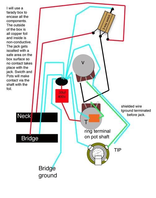 ( EDIT: Fixed the thread title, it had somehow grown a bit long.....  |
|
|
|
Post by sumgai on May 19, 2009 11:45:26 GMT -5
ange, As you show it, the wire to the bridge/strings will offer no protection! Connect it as Fender has always done, directly to the cavity shielding (with a screw), or soldered directly to the back of a pot. The rule of thumb is, in order for a player to be protected from possible shock, anything (metallic) that can possibly be touched must go through the capacitor in order to get to the jack's ground terminal. HTH sumgai |
|
|
|
Post by ChrisK on May 19, 2009 17:09:20 GMT -5
I want to echo what sumgai is saying. Understanding what is intended is vital to ensuring what is safe (and not pointless).
For an isolation cap to make sense, its two leads are connected to two separate nodes that are isolated from each other. If there is conductivity between these two nodes, there IS NO isolation.
One node is the signal return path. This starts at the output jack sleeve and is connected to all internal signal return points.
The other node is the operator touchable stuff. This starts with the strings and is connected to anything and everything conductive that a human (or chipmunk) might touch. This includes metal (conductive) knobs, strings of course (and hence the bridge), pickup covers if conductive, screws if in contact with internal shielding, etc. All of these conductive components must specifically not be connected to the signal return node.
Think of it as two enemy nations (or parties in a divorce) separated by a De-Militarized Zone. The cap is the DMZ (lawyers).
If metal knobs are used, and the pots have metal shafts (the usual case), then the pot back shells must not be connected to the signal return node.
The output jack is usually not an isolated sleeve jack, so in the case of a Strat, the jack plate is connected to the sleeve/threaded barrel of the output jack, and hence signal return node and is inherently dangerous to touch.
On a Tele, the output jack cup or mounting plate is similarly connected to the signal return node.
The signal return node
This is the internal untouchable node. This is what is usually connected to this node.
The output jack sleeve.
The pickup signal return wires that are galvanically isolated from any metal cover.
This is easy on a Strat or guitar with simple two wire pickups.
On a Tele bridge pickup, this means that the signal return wire should go to this node and a separate bridge plate ground wire should be added going to the touchable stuff node. This additional wire must not be electrically common with the signal return wire.
On a Tele neck pickup, this means that the signal return wire should go to this node and a separate neck cover ground wire should be added going to the touchable stuff node. There is usually a jumper wire on the bottom of the pickup that must be removed and this additional wire must not be electrically common with the signal return wire.
A pickup with coil leads separate from the shield is easy; the coil leads go to the circuitry leading to the signal return node and the shields go to the touchable stuff node. Measure the resistance from any shield connection on a pickup to ALL other wires coming from said pickup. If any reading is less than 100K or so, presume that the shield IS NOT isolated from the coils and treat the pickup the same way as a single conductor with shield pickup.
On a single conductor with shield pickup, this is problematic. While the conductive cover/shield wire could go to the signal return node for signal quality reasons, in actuality it must be connected to the touchable stuff node for safety reasons.
The pot signal return terminals. These terminals are commonly bent over and soldered to the pot back shells. If the pot back shells/shafts/metal knobs are touchable, these bent connections must be removed and the pot signal return terminals connected to the signal return node. On a volume pot, this is the "0" CCW terminal. On a tone pot, this can vary; since a tone control is usually a two-terminal adjustable resistor and a cap, the order of the resistor and cap does not matter. Connect the same "0" CCW terminal to the "0" CCW terminal on the volume pot. If possible, connect the wiper terminal on the tone pot to the applicable terminal on either the volume pot or 5-way switch USING THE TONE CAP AS THE JUMPER . This is simple and reduces the complexity of terminating the tone cap to the isolation cap.
The tone cap could also be used as the jumper from the "0" CCW terminal of the tone pot to the "0" CCW terminal on the volume pot, which may be the idea signal ground reference point.
The Touchable Stuff Node
This is the externally touchable node. This is what is usually connected to this node: ANY conductive thing that might be touched by the operator or bystander (innocent or not).
The bridge ground wire. This AC grounds the fixed or vibrato bridge.
Any metal (conductive) knob/shaft/pot shell that exposes the operator (or drunk onlooker/toucher) to any conductor coming from the amp via the guitar cord.
If the pot back shells/shafts/metal knobs are touchable, the bent terminal connections from the signal returns must be removed and the pot signal return terminals connected to the signal return node, and the pot back shells connected to the touchable stuff node
Any metal (conductive) pickup cover.
Any frame ground terminal on a switch such as the LP toggle or 3/5-way lever.
ANY conductive thing that might be touched by the operator or bystander.
Comments?
|
|
|
|
Post by angelodp on May 19, 2009 17:23:52 GMT -5
I am studying up..... splendid as always.
thanks Ang
|
|
|
|
Post by angelodp on May 19, 2009 18:09:33 GMT -5
Ok, sorry if I am slow on this stuff, but this seems to be correct now. The Faraday box is used because the dano cavity is such that lining it would be impossible. The box is constructed of heavy cardboard with copper foil around the outside ( continuity along all sides ), the interior is non conductive and does not carry any signal. 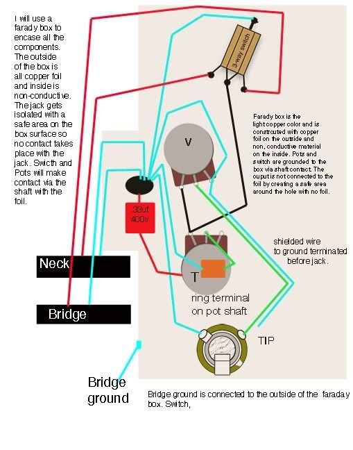 |
|
|
|
Post by angelodp on May 19, 2009 18:37:23 GMT -5
And if I decide to go with a series parallel switch for the two pickups, is this looking ok. 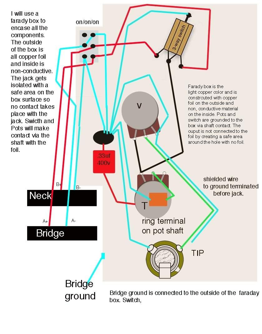 |
|
|
|
Post by ashcatlt on May 19, 2009 19:03:09 GMT -5
I think you've got the shielding and iso stuff taken care of here. I'm not at all confident in that "S/P" switch. I've got too many screaming children around to sus* it out right now. I do wonder though: An S/P switch needs 2 positions - S and P - the switch you've specified has three...  Also, what's the deal with that blue wire running alongside the green between V and Jack? *I prefer the second, but a fourth would work in a pinch. |
|
|
|
Post by angelodp on May 19, 2009 19:27:41 GMT -5
I was referencing this article that showed the switch i used. Is that not correct. The blue wire is the terminated shield of that wire. I was under the impression that the shield was meant to be a drain and not connected. |
|
|
|
Post by ashcatlt on May 19, 2009 19:59:14 GMT -5
But that's not exactly what you've drawn there for the switch, is it?
The blue wire is only connected at the pot end? That's alright as long as you take care not to allow it to make contact with the "touchable node". On the other hand, since it's inside the faraday cage, it's kind of redundant, no?
|
|
|
|
Post by angelodp on May 19, 2009 20:06:25 GMT -5
Sorry ashcatt but that has totally confused me, there are numerous blue wires, which one are your referring to. None are connected to a pot??
ange
|
|
|
|
Post by ChrisK on May 19, 2009 20:17:16 GMT -5
Two issues; The first is one of practice with relying on the copper shield to connect all pot shells/bushings. I still solder a wire connecting the shells together since a shield is a shield, and not a conductor. Also, it is copper and the switch hardware is either plated steel or plated brass, both of which will corrode differently than copper. The second is a safety issue with the light blue wire coming from the 3-way pickup selector switch and going to the signal return (the sleeve of the output jack). This connection on this switch serves no purpose other than to connect the metal frame of this switch to a ground point (the touchable stuff node). On one end, it's connected to the signal return and thru its mounting bushing it's connected to the shield. The isolation cap is shorted, and hence, compromised. This wire should connect the frame of this switch to the shield/cage (redundancy is a religion too) by soldering it to an interconnected pot shell, or if you're especially "faithful", just mechanically touching the shield. Understanding is seeing, in safety.  |
|
|
|
Post by newey on May 19, 2009 20:26:21 GMT -5
Ange-
You describe using a DPDT "On-On-On" switch, and your diagram shows it wired, (as per your reference) to give Series/single/parallel, If that's what you want, fine- you originaly indicated only series/parallel. It's your choice as to which of the 2 pups is active as a "single" in the middle switch position, depends on which one you designate as "pup A" and which as "B".
But I'm not sure that this arrangement will work with your regular Gibson 3-way.
If you really want "neck pup/both pups series/ both pups parallel/ bridge pup", I advise replacing the 3 way Gibby toggle with a single switch to do it all. This could be done with a rotary, and I think there is even a hard-to-find 4-position toggle out there somewhere.
Alternatively, you could use 2 SPDTs and use binary tree switching.
|
|
|
|
Post by ChrisK on May 19, 2009 20:31:44 GMT -5
Or a DPDT toggle and do a series override that puts both pickups in series regardless of the position of the three-way pickup elector.
|
|
|
|
Post by newey on May 19, 2009 20:39:45 GMT -5
And, Chris means a regular DPDT "on-on" switch, not the DPDT "Center On" (or "On-On-On") as indicated in your diagram.
|
|
|
|
Post by angelodp on May 19, 2009 20:50:40 GMT -5
I have been doing some sloppy work here. I meant to do a series parallel switch only ... not a series / single/ parallel arrangement. I also noticed that my wires from the output jack are incorrect as I should be using a 2 wire conductor w/ shield wire. I then assume that the shield is terminated at one end. Is that nay different than using a single unshielded wired to the sleeve and using a single conductor w/shield from the tip and terminating that shield on one end. I will redo some graphics and repost soon. Thanks for hanging in there with me, you all have the patients of Job.
ange
|
|
|
|
Post by newey on May 19, 2009 21:31:27 GMT -5
Job was a doctor? ;D ;D
The point of using a two-conductor with shield to the jack is so that both wires are encased in the shield. Running one wire separately defeats the purpose. The shield is terminated at the jack sleeve, along with the "negative" jack connection.
|
|
|
|
Post by angelodp on May 19, 2009 21:35:47 GMT -5
One more try, I have implemented several suggestions. I hope that i am getting closer here. I want to have the two pickups available for series/parallel switching. I think that the shielding issues have been addressed. Can I presume that in either series or parallel ( assuming this scheme is correct ) that I will have a hum canceling effect. Small correction I meant to say that the shielding is connected at the sleeve but is not connected at the pot end. best ange 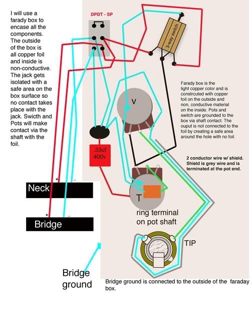 |
|
|
|
Post by ashcatlt on May 19, 2009 22:19:53 GMT -5
...there are numerous blue wires, which one are your referring to. None are connected to a pot?? Well, I don't know what color they are to you , but I see a blue wire running from the ground lug of the Vpot toward (but not quite to) the jack in all but the last of your posted pics. I guess this is supposed to be the shield on that single conductor+shield cable. When wiring certain types of pedals - those with very high gains, and sometimes those with clocks - it's a good idea to use shielded cable inside the enclosure. This is to stop crosstalk and induced interference between various parts of the circuit inside the enclosure. I do not believe this is usually meant to help with shielding from RFI which originates outside the enclosure since the enclosure itself accomplishes this. Now it's my understanding that the entirity of your wiring resides inside the enclosure. I don't think you're going to get any meaningful crosstalk. So I figure that shielded wire is not particularly useful in this instance. We use it when wiring strats because it's easier than trying to shield the interior of that hole which connects the control cavity to the jack cavity. |
|
|
|
Post by angelodp on May 19, 2009 22:26:23 GMT -5
Right you are... i am having one of those days. But how does the rest look.
ange
|
|
|
|
Post by ashcatlt on May 19, 2009 22:52:29 GMT -5
Your S/P switch still has both pickups always connected to both ground and hot (in this case, the 3-way switch). As shown, it will short across the Bridge pickup when flipped toward "series". I'm pretty sure that ain't what you're shooting for. The most recent picture of the series override switch I pulled up in a search was from this thread, and looked like this:  |
|
|
|
Post by angelodp on May 19, 2009 23:29:59 GMT -5
Ok another try...are we there. ange 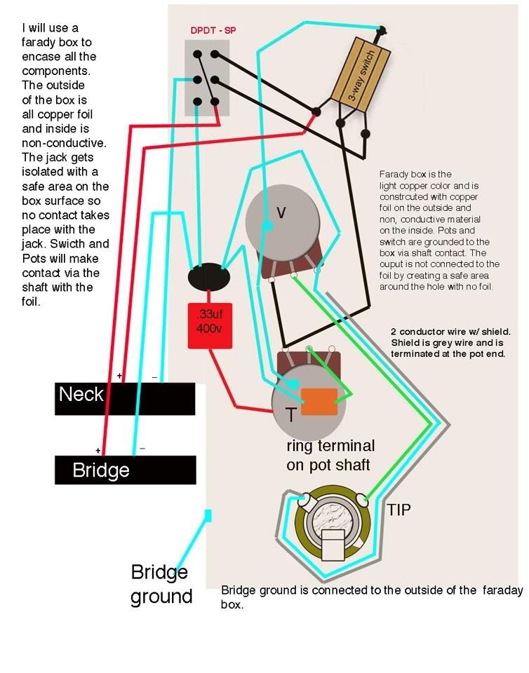 |
|
|
|
Post by newey on May 20, 2009 10:28:43 GMT -5
Ange-
In order to do series/parallel, both connections from each pickup are used as signal carriers, and neither goes directly to ground. You show your bridge pup wired to the safety cap before going to the S/P switch. This is incorrect, that wire needs to go straight to the S/P switch and not to the safety cap.
|
|
|
|
Post by ashcatlt on May 20, 2009 12:04:29 GMT -5
newey, he'd just end up connecting it to the grounded lug of the switch anyway. He has exactly copied the S/P switching from the picture I linked (which came from Wolf) and it should work just fine.
ange, unless I'm missing something I think you're done here. You still don't need that shielded wire inside the faraday box, but it's not hurting anything, so...
|
|
|
|
Post by sumgai on May 20, 2009 13:58:16 GMT -5
In order to do series/parallel, both connections from each pickup are used as signal carriers, and neither goes directly to ground. You show your bridge pup wired to the safety cap before going to the S/P switch. This is incorrect, that wire needs to go straight to the S/P switch and not to the safety cap. Errrr, come again? In point of fact, in the simplest possible setup for a series/parallel relationship, one of the two hot leads is always tied to the positive side of the outgoing jack (or any switching/controlling components leading directly to that point), and the opposing coil's negative lead is always tied to ground. One can eliminate the hanging hot, but only at the expense of complexity. I'll refrain from repeating what ash said about electricity flowing towards the same final goal, no matter where the Bridge negative wire is physically attached. </end remedial training lesson  > sumgai <edited because some yo-yo made an error that should have been obvious to everyone, but only ashcatlt caught it, and that was well after the fact.> |
|
|
|
Post by angelodp on May 20, 2009 15:58:57 GMT -5
I eliminated the shielded wire, and I also ran the Bridge negative wire to the switch. Question is now do I take that wire and continue to the safety cap?? ange 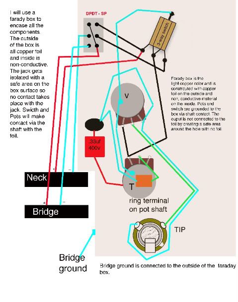 |
|
|
|
Post by newey on May 20, 2009 18:33:18 GMT -5
Ange, I stand corrected by higher authority!
I hope you haven't actually been rewiring this as we go along here.
Both Ash and Sumgai have now vetted your design, so wire away.
|
|
|
|
Post by ChrisK on May 20, 2009 19:07:31 GMT -5
tedfixxIt isn't that complex...... No. The last drawing is GeFooey. We're fencing in the dark here. Someone's going to lose an eye or a 'nad or something. THIS ONE was correct. Just remove (or ignore) the GREY wire that represents the shield around the two wires to the output jack.
|
|
|
|
Post by angelodp on May 20, 2009 19:22:48 GMT -5
How did you know i was a fencer and yes I was stabbing away. I need to get my head straight on this stuff. I have yet to re-wire and so i was waiting for the go ahead form the larger group. Once again i am indebted to you all for the help on this. ange |
|
|
|
Post by ashcatlt on May 20, 2009 19:53:55 GMT -5
The one that ChrisK quoted is the one sumgai and I said was correct, but... I eliminated the shielded wire, and I also ran the Bridge negative wire to the switch. ange Question is now do I take that wire and continue to the safety cap?? ...you could do that too. I modified the quote to flow with my post here a little better. |
|
|
|
Post by angelodp on May 20, 2009 20:15:10 GMT -5
ashcatlt, are you saying the drawing in your last post would also work with the additional wire down to the safety cap? Also, now that I am doing the pots as linked by the shell wire from pot to pot, do I need to isolate the pots and the switches from the faraday box or does it matter.
ange
|
|


 >
>