rhager11
Apprentice Shielder

Posts: 28
Likes: 0
|
Post by rhager11 on May 21, 2009 12:01:32 GMT -5
Hi folks,
I am new to the site and thought someone may give me some clues to solving a problem I am having with my new strat wiring. I will try to best describe my setup.
I tried to follow the "Taming the Beast" shielding guide. I glued aluminum foil in the cavity, Grounded the trem to the foil with a ring connector and glued a foil coating on the pick gaurd. My setup is Lace sensor blue(neck) Lace sensor Silver(middle) and Seymour Duncan Hot rail humbucker(bridge). I have CTS 250K pots, a push/pull volume pot which I am using to control the neck pickup and a DPDT switch to split the Hot Rail.
I consulted the Seymour duncan and Lace sensor wiring diagrams and followed those except that I used "star grounding" as shown in the shielding instructions. Instead of grounding to the pots, I connected all grounds to a ring connector that is connected to a .033 orange drop cap which is connected to a large ring that fits under the middle tone pot.
My bridge pickup works fine. The coil split is fully functional and I seem to get full volume and decent tone from that pickup. The problem is that middle pickup sounds thin lifeless and the neck pup is really quiet and almost no sustain. There is a significant drop in tone and volume and you move from bridge to middle and again when you move from middle to neck.
I inspected all of my connections and they look OK to me. Any advice for troubleshooting before I cave in and go with the more traditional grounding?
Thanks!
|
|
|
|
Post by D2o on May 21, 2009 12:16:38 GMT -5
Hi, rhager11, and WELCOME to GN2!
We can certainly get you sorted out ... or at least shorted out.
But first, can you clarify:
When you move towards the middle and the neck pups, is it thin and lifeless in positions 4 (M&N) and 2 (M&B), or is it in positions 5 (Neck) and 3 (Middle)?
Cheers,
D2o
|
|
|
|
Post by ChrisK on May 21, 2009 12:19:08 GMT -5
You may have effectively put a 0.033 uF cap (why did you use this value) in series with the pickups. This would be a high-pass (low-cut) filter.
Please post well-focused pics of the wiring.
|
|
rhager11
Apprentice Shielder
Posts: 28
Likes: 0
|
Post by rhager11 on May 21, 2009 13:42:31 GMT -5
Position 1 sounds normal. Position 2 sounds pretty decent as well with bridge and middle. There is a notable drop off in position 3(middle only) not near what I expect out of an LS silver. Position 4(middle and neck) not much different than pos 3. Position 5 signal is really weak, sustain cuts out quickly.
I will take some pics and post tonight when I get home. As to why I chose the .033, this is my first complete wiring job and I had a .022, .033 and .047 orange drop to choose from. I have read various things about the different cap values but didn't really have much of a frame of reference to go on so I arbitrarily went with the .033. I'm not intent on staying with this cap so if it would help, I would go with a diffent value. In other words, I'm still in the experimental stage.
Thanks for the help! This site is a great resource!
|
|
|
|
Post by D2o on May 21, 2009 14:29:12 GMT -5
Thanks, hager
We'll wait for the pics. I am not sure, but I think ChrisK was pointing out .033uF as opposed to .33uF - i.e. if the intent is to have a DC blocking cap.
Cheers,
D2o
|
|
|
|
Post by ChrisK on May 21, 2009 17:11:13 GMT -5
We don't know what these mean (we can't see them).  Yes, I'm trying to "see" what "Instead of grounding [?what?] to the pots, I connected all grounds to a ring connector that is connected to a .033 orange drop cap which is connected to a [?second?] large ring that fits under the middle tone pot." means. "...to a ring connector that is connected to a .033 orange drop cap which is connected to a large ring that fits under the middle tone pot." would seem to indicate that you have all grounds going thru a 0.033 uF cap to the pick-guard shield. What are you trying to do with the 0.033 uF cap? Why is it between two ring connectors? Are you confusing/combining a 0.033 uF tone cap with a 0.33 uF 400 VDC safety isolation cap? |
|
rhager11
Apprentice Shielder
Posts: 28
Likes: 0
|
Post by rhager11 on May 21, 2009 20:16:34 GMT -5
Are you confusing/combining a 0.033 uF tone cap with a 0.33 uF 400 VDC safety isolation cap? Yes, I believe you are correct. I have the wrong value cap as a safety isolation cap between 2 ring connectors. Could this be the cause of my issue? Here are the links to the basic wiring diagrams I followed to make sure I got the wiring right for my pickups. www.lacemusic.com/wiring/pdf/1.pdfwww.seymourduncan.com/support/wiring-diagrams/schematics.php?schematic=1h_2s_1v_2t_5w_splitI used the shielded strat diagram in the link below for the grounding. The C1 cap is a .022 orange drop and the safety cap is a .033 orange drop. When I figure out how to post pics, I'll put up the shots I took tonight. |
|
|
|
Post by angelodp on May 21, 2009 20:56:43 GMT -5
photobucket works pretty well for posting pics here.
|
|
|
|
Post by newey on May 21, 2009 21:26:47 GMT -5
Image postingI don't know if the wrong safety cap is the cause of your problems, but I also don't think it'll do you much good as a safety cap, either. So you could swap it out for the correct one while we await some photos. Easier still, if you don't have the correct cap around, you could remove it and jumper a wire across its position temporarily to test it without that cap. Use a solid-state amp to test, since you won't have the safety cap to protect you if using a tube rig. I have my doubts that this is the cause of the problem, however, so you may want to get those photos up afore you start "revising" things. I don't know squat about Lace Sensors, but it seems that they are the problem, not the HB, as you indicate only positions 3,4, and 5 are the problem ones.
|
|
rhager11
Apprentice Shielder
Posts: 28
Likes: 0
|
Post by rhager11 on May 21, 2009 22:07:17 GMT -5
Yeah, I don't have the correct value cap so I'll have to order some. I may try and test a jumper in the meantime. OK here goes my attempt to post pics. Sorry but this was the best I could get. The flash was too bright in many of my pics due to the foil on the pick guard. I'll try to get some better ones when I have more time. The other thing I think that may be an issue is that I did not insulate the ground ring. Any suggestions besides tape to do this job. I don't think anything is contacting it when the pick guard is isntalled but ya never know. 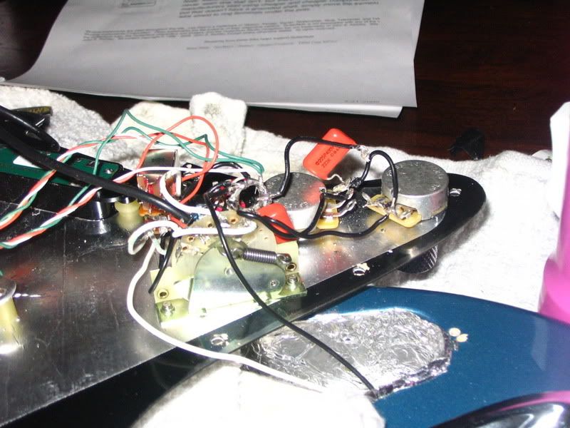 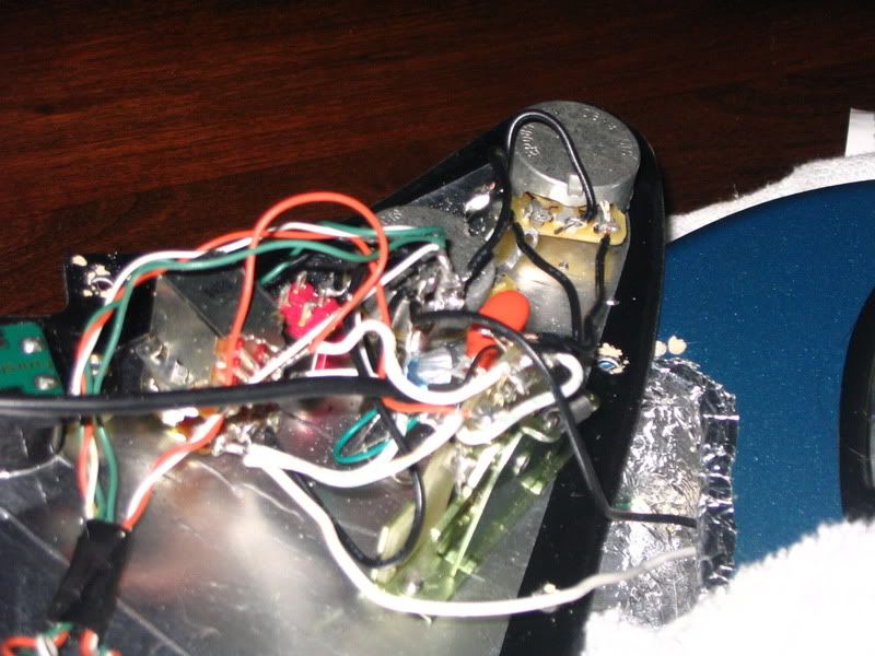 |
|
|
|
Post by ashcatlt on May 21, 2009 23:05:21 GMT -5
I can't comment on the wiring there right now.
I did notice that the tone cap is rated for 400V. That is a good sign. This is actually the most important value from a safety standpoint with the other (isolation) cap.
The capacitance value helps to determine the cutoff frequency for the hi-pass filter through which the noise (captured by the shield) must pass on its way toward silence. All caps block DC, which is what we want it to do. The wrong value might allow more noise through, which is what we don't want it to do.
|
|
|
|
Post by sumgai on May 22, 2009 0:35:29 GMT -5
|
|
rhager11
Apprentice Shielder
Posts: 28
Likes: 0
|
Post by rhager11 on May 22, 2009 9:20:27 GMT -5
Just wanted to clarify that one picture was taken before I added the .022 cap to the middle tone pot. Making that change did not correct my problem.
|
|
|
|
Post by D2o on May 22, 2009 9:44:36 GMT -5
Hager, Thanks for the pictures ... the first one is very clear ; the second not so much ... and you know what? Even if they were both clear it would still be hard to see what's going on amongst all of those wires. How are you with MS Paint? or doing a freehand sketch and scanning it or something so that we can see exactly what's going on? ... something similar in layout / appearance to the schematic below. Before doing that, has anyone asked you what the distance between the neck and middle pickups and the strings is? Cheers, D2o 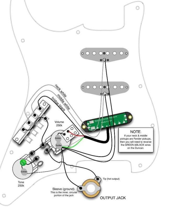 |
|
rhager11
Apprentice Shielder
Posts: 28
Likes: 0
|
Post by rhager11 on May 22, 2009 10:39:54 GMT -5
Thanks D2o,
I'll give it a shot in MS paint. You wouldn't happen to to have a shell picture without wiring that I could use as a start point would you. I'll look around a bit for a pic with just the pickups, pots and jacks etc...
Bob
|
|
|
|
Post by ashcatlt on May 22, 2009 11:12:50 GMT -5
That picture is clear enough for me to be fairly confident that the jack sleeve is on the correct side of the iso cap, which I think was an early concern.
That thing about the pickup height is a great idea. Usually the first thing to check when you're having volume/balance issues between a set of pickups. It's the easiest to overlook and the easiest to correct
|
|
|
|
Post by D2o on May 22, 2009 11:19:13 GMT -5
That thing about the pickup height is a great idea. Thanks, Ash! Hager - This is butt-ugly ... I hope it helps. 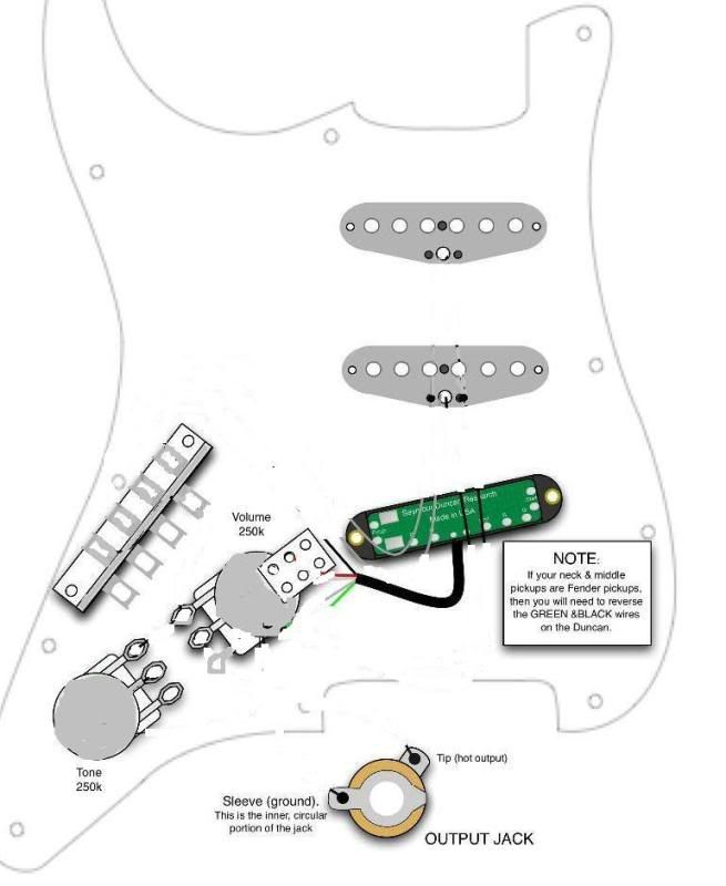 |
|
rhager11
Apprentice Shielder
Posts: 28
Likes: 0
|
Post by rhager11 on May 22, 2009 14:31:43 GMT -5
Hey, it turned out better than I thought(I know, it's not that great ) Let me know if anything is not clear. Thanks, Bob |
|
rhager11
Apprentice Shielder
Posts: 28
Likes: 0
|
Post by rhager11 on May 22, 2009 14:32:29 GMT -5
Oh yeah, here's the diagram....  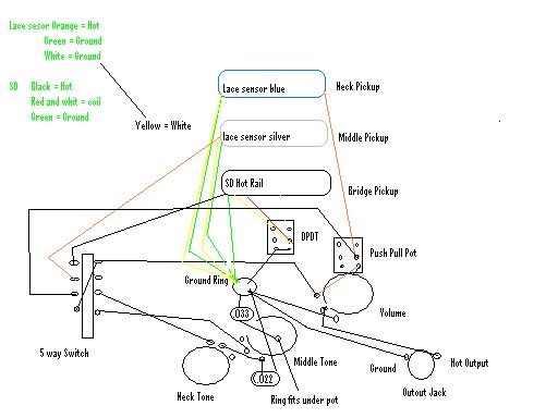 |
|
|
|
Post by D2o on May 22, 2009 14:40:37 GMT -5
Good stuff, Bob.  I'm nearly outta here for the weekend ... Not to worry though - this looks right up the alley of a few members here. Hang tight, and have a great long weekend. D2o |
|
rhager11
Apprentice Shielder
Posts: 28
Likes: 0
|
Post by rhager11 on May 22, 2009 15:00:43 GMT -5
Thanks D2o,
About the pickup height, The neck pickup is currently at an angle with one edge almost touching the strings due to a wiring screwup I had my first go around. I have to push it down to keep it from touching the strings.
The diagram sent with my lace sensor was a seymour duncan scheme and it had the black as the hot. When I consulted the lace sensor website, I discovered that orange was hot. Unfortunately, I cut the ground wire to go to the 5 way switch instead of the ground ring. Anyway, the wire is pulled tight so it does not route in the cavity channel so it pulls on the pickup. When I get a chance, I am going to splice in a length of wire so it all routes nicely.
So far, here are my known issues:
1. Ground ring not insulated
2. Wrong cap value for safety loop
3. Ground wire on neck pickup too short, not routing through channel.
|
|
|
|
Post by D2o on May 23, 2009 18:25:34 GMT -5
Don't put any weight on this thought, because I actually have no good reason for the persistent nagging feeling that your pickups are somehow out-of-phase ...  |
|
|
|
Post by newey on May 23, 2009 19:00:08 GMT -5
D2o said:
I got that same nagging feeling, too, but I keep coming back to his statement that the middle alone and neck alone are affected.
|
|
rhager11
Apprentice Shielder
Posts: 28
Likes: 0
|
Post by rhager11 on May 24, 2009 0:19:54 GMT -5
I hear where you're coming from with the "out of phase" thought. I put an SD Pearly Gates in my Les Paul and didn't connect and insulate the red and white wires(that are used for coil splitting) and I got the same kind of weak signal, cutoff sustain sound that I am getting now with my Lace sensor neck pickup. Also, Like I said, the first time I wired this guitar, I had the lace sensor white wires as the Hots and it sounded the same as it does now with the orange as hot. Didn't try the greens yet |
|
|
|
Post by D2o on May 25, 2009 9:47:37 GMT -5
Yes, you could experiment with that - you've got the current wiring on record here so that you can always go back to it ... feel free to keep on trying because we're not coming up with much in the meantime.  I honestly don't know if this is an issue at all - especially as you say that the coil split part of this works fine ... but I am wondering about the wire that's leading from the pot terminal to the to the actual push-pull terminal (I have indicated it in blue). I don't know if maybe that should be going to ground. It's doubtful ... I'm kinda just grasping for anything that might lead to something else that could solve your problem. 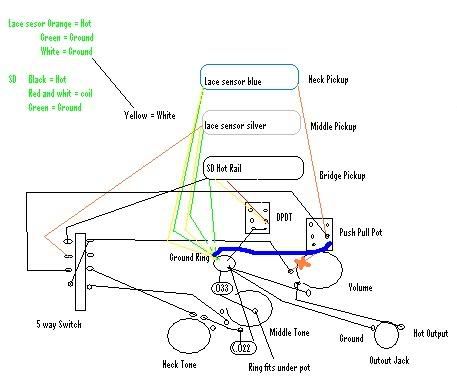 EDIT EDIT ... I am slightly more sure that you should NOT be having that TONE cap connected to the same place as the SAFETY cap, however. Should it not be soldered to the back of the tone pot, regardless of whether the QTB mod is used? D2o 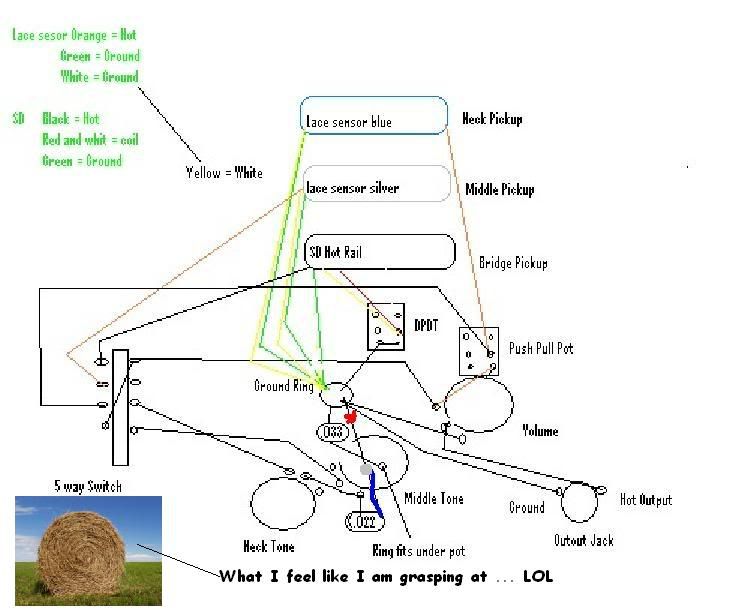 |
|
|
|
Post by ashcatlt on May 25, 2009 16:08:36 GMT -5
I honestly don't know if this is an issue at all - especially as you say that the coil split part of this works fine ... but I am wondering about the wire that's leading from the pot terminal to the to the actual push-pull terminal (I have indicated it in blue). I don't know if maybe that should be going to ground. It's doubtful ... I'm kinda just grasping for anything that might lead to something else that could solve your problem. That particular switch is a "Neck On" switch, and I think it's wired correctly. Connecting that wire to ground would make it act as a kill switch any time the neck pickup is selected - whether alone or in combination. Ignoring our recent discussions about the actual practicality of that "safety cap"the answer is no. The "ground end" of the tone cap should go the same place as all the rest of the signal returns. |
|
|
|
Post by D2o on May 25, 2009 17:34:10 GMT -5
I'm not sure if we're spleakin' the same language, but I don't seem to recall ever seeing anything about the TONE cap going to star ground ... does it? Here's a diagram - I believe it's supposed to be after star grounding - reminding the modder to remove ground loops (fodder for another day). The TONE cap is still soldered to the pot case, as it was. No? ![]() |
|
|
|
Post by newey on May 25, 2009 20:21:10 GMT -5
D2o-
Read 1 step further in JA's instructions. The diagram you posted is at Step # 17. Step 18 reads:
Ash is correct, it needs to go to the star grounding point. Assuming one is implementing a complete star grounding scheme, the back of that pot shell is only going to be connected to your shielding foil.
|
|
|
|
Post by D2o on May 26, 2009 8:46:15 GMT -5
D2o- Read 1 step further in JA's instructions. The diagram you posted is at Step # 17. Step 18 reads: Ahhh ... Ash, you are correct (not that it should come as a surprise). I subsequently had a look at some of Ange's diagrams (I like it because it shows EVERYthing), and here is how he has laid it out: 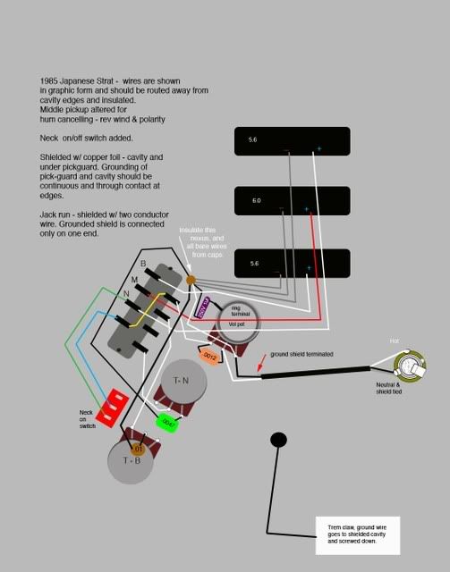 I guess I should actually do the whole-hog QTB one of these days. I have shielded many a guitar - with fine results - but have yet to go to the trouble of the star-grounding. D2o |
|
|
|
Post by ashcatlt on May 26, 2009 23:34:33 GMT -5
Star grounding is a "best practices" kind of thing. I haven't yet heard anybody make a convincing argument that it actual makes much difference in a guitar. I have heard several convincing arguments that it just plain can't.
I do it because it just makes more sense to me.
Anyway, the usual practice of soldering the grounds to the back of the pots creates a sort of "ground bus", which is about the same thing as star grounding.
|
|