razbo
Apprentice Shielder

Posts: 36
Likes: 0
|
Post by razbo on Jun 7, 2009 8:18:51 GMT -5
Making an HSS type guitar. Got a push/pull for the HB to coil tap. I can't decide if I should make that a volume control, or a tone control.
In total I have 4 pots to play with: 3 * 250k, and the push/pull is a 500k and I think 3 caps. I am using the StewMac Golden Age pick ups if that has any bearing.
I had originally thought to make the p/p a tone control, because I really only wanted one volume control, but then I got thinking when tapped (or not) I might be getting different output levels from the HB and maybe a volume on it would be better for blending with the SCs.
Any suggestions with regard to that pot are welcome and also any suggestions/opinions as to overall configuration of knobs.
TIA. My build is moving inevitably to conclusion!
|
|
|
|
Post by JohnH on Jun 7, 2009 16:19:03 GMT -5
Apart from the pots, what sort of switches are you using?
John
|
|
razbo
Apprentice Shielder
Posts: 36
Likes: 0
|
Post by razbo on Jun 7, 2009 19:23:40 GMT -5
A 5 way Strat style knife switch. Basically the StewMac strat wiring kit plus the push/pull pot.
As of this moment, I'm tentatively thinking a volume & tone for the HB and a volume & tone for the both SCs.
I am not necessarily trying to use all 4 either, if some strategy would be good using three or even two pots. (However, I sense within the GN2 culture, more is better, anyway ;D)
|
|
|
|
Post by ChrisK on Jun 7, 2009 21:49:25 GMT -5
More isn't always better, but it is usually more. Sometimes it is more better.  |
|
|
|
Post by JohnH on Jun 8, 2009 0:48:23 GMT -5
Those Stew Mac pickups look like good value. I see that the HBs are wired with 3 wires, being hot, ground and centre connection. Thats not quite so versatile as 4 plus bare shield, but OK for some good coil cutting options.
To get as much as possible out of your parts, I reckon it would be good to be able to combine neck and bridge, optimise humcancelling between different coils and also get some in-between variations on your coil splitting. How about this, using three pots, the standard 5-way and the push/pull on one of the pots.
The knobs would be master 250k volume, 500k push/pull as tone, and a 250k for variable coil split.
Push/pull down, you could have standard Strat options, incorporating the full bridge humbucker
Push/pull up, splits the Hb, but with the 3rd pot controlling how much it is split (ie, the extent to which one coil is shunted), plus at the same time, the second half of the 5-way controls whether it is split to the north coil or the south coil, so that when fully split, it is as near as possible humcanceling with both the neck and middle. The push/pull also forces the bridge pup to be on, giving N+B and N+M+B options, with the bridge splitting under pot control.
So for push/pull up mode, it could have:
N + BridgeHb blended towards N+ BridgeSc
N + M + BridgeHb blended towards N+ M+ BridgeSc
M + BridgeHb
M + BridgeHb blended to M + BridgeSc
BridgeHB blended to BridgeSc
Any use? If so a sketch diagram can be provided.
John
|
|
razbo
Apprentice Shielder
Posts: 36
Likes: 0
|
Post by razbo on Jun 8, 2009 7:13:18 GMT -5
Just to be clear, soldering flashlight bulbs to batteries is about the extent of my electronic wizardry.  Nevertheless, I am making progress and I understand what you are saying and it sounds interesting. I guess my concern to be assuaged or not is whether the HB in HB mode is going to give the same output (volume) as the HB in SC mode. If I need not be concerned, then this idea takes me from what I figured was going to be 7 distinct sounds (notwithstanding tone adjustment) to theoretically infinite. Any use? If so a sketch diagram can be provided. This would be greatly appreciated. Those Stew Mac pickups look like good value. If you say so.  I just picked up electric guitar a few months ago, so I have no experience with different kinds of pick ups. I figured these could establish kind of a baseline for me to compare others with. |
|
|
|
Post by JohnH on Jun 8, 2009 15:49:23 GMT -5
The Hb in coil cut mode has less output, since only one coil is active. Its not really a problem, just part of its character. Ill put up a schematic in a day or so of what I was on about.
John
|
|
|
|
Post by ChrisK on Jun 8, 2009 16:45:55 GMT -5
Having four pots in a Stratty design is a luxury. You could go with one tone per pickup or have a SC tone and volume as well as a humbucker tone and volume. Now, if you do the latter, using the Red Rhodes (Peavey) Tone_Coil Split Pot will give you a functional tone on the humbucker as well as the ability to split it, either resistively or resistance/capacitance wise for combination with the SCs. One can even do more wild crazy stuff by using the unused terminal on the traditional high-cut tone control to blend-in other pickups (such as the bridge into the neck), as exposed in The FREE Neck On Switch. One could have the tone control for the SCs split/blend in the humbucker from aboot "7.5" to "10" (use a 500K pot). NOTE: THIS FREE INFORMATION IS IN THE PUBLIC DOMAIN. THIS BLENDING CONCEPT HAS BEEN PUBLISHED (LEGALLY DISCLOSED) HERE FOR OVER A YEAR AND HENCE IS PRIOR ART FOR ANY DISCLOSURE TO THE USPTO. THE FACT THAT IT HAS BEEN PUBLICLY DISCLOSED AT ALL RENDERS IT PRIOR ART FOR THE PCT. IT CANNOT BE USED AS A CLAIM OR PART OF A CLAIM IN ANY DISCLOSURE. IF OBSERVED AS SUCH (I do check), THE USPTO/PTC WILL BE NOTIFIED OF FRAUD. |
|
|
|
Post by JohnH on Jun 9, 2009 6:59:11 GMT -5
Here is what I was talkin' about:  This a schematic, which shows how it works. Combinations are in my post two above. Can you follow this diagram? It probably needs a wiring diagram too, to show how to build it. Its not a hard build, and it uses the parts that you have. I think it could be quite interesting because you get a standard selection of Strat settings, plus the missing N+B and N+M+B, plus a range of coil cuts and combinations, without a lot of fiddly extra switches. I find that when a bridge pickup is cut to a single coil, it is often a bit too thin sounding, but this allows you to set the exact degree of coil cutting with the pot, and switch quickly from that to full Hb with the push/pull pot. The two halves of the 5-way switch are shown, and the one on the left does that main pup selsction, while the one on the right has the job of selecting which of the Hb coils gets cut, for optimum hum cancelling. There is the possibility that the connections to this right side need to be swapped, depending on the polarity of the Hb coils compared to the Sc pup coils. The two poles of the DPDT push/pull switch are shown in eth centre, and one forces the bridge pup to be on, and the other engages the coil cutting, to the extent determined by the pot. On the volume control are a 1nF cap and 220k resistor. These are 'treble bleed' help to keep the treble intact as you roll down the volume. They are optional, and they only work at reduced volume and are not provided on most guitars. If you think this is interesting and can follow the diagram, perhaps you could have a go at the wiring diagram and Ill check it , or if the schematic is less than clear, I could do it if you think the scheme has legs. John |
|
razbo
Apprentice Shielder
Posts: 36
Likes: 0
|
Post by razbo on Jun 9, 2009 10:22:10 GMT -5
Maybe. Eventually. It's something I need to be able to do, so I will have to.  [Edited...] Actually, except for the switch part, it seems easier to understand. Part of me keeps whispering " KISS!", but I think I'll go for it! Anything you can provide (like a dumbed down diagram) to help me would be much appreciated. I will Exalt you a whole bunch! It would be nice (for me) to exclude as many non-essential elements as possible. Using the blend that way, will I get full-on HB output when turned that way? Will there be enough pot resistance to make it something less than a non-split HB when I want it that way? Remember, I'm establishing a baseline on pick ups here as well. |
|
|
|
Post by JohnH on Jun 9, 2009 15:54:16 GMT -5
OK, well Ill do a wiring diagram, which is one that is laid out to look more like the parts as you wire them up. A couple of days possibly.
When the pp switch is pushed down, as normal, you get the full Hb without any splitting. But also, when it is pulled up, I expect that at one end of the coil cut pot travel youll also get audibly the full Hb (even though one coil is slightly bypassed), or you can turn down to just one coil. So you dont miss out on anything.
John
|
|
|
|
Post by newey on Jun 9, 2009 18:03:50 GMT -5
John-
At the outset, razbo indicated that he had 4 pots in this design. Your scheme uses only 3. Before we start confusing things for razbo here, and before any diagramming starts, we should clarify if he wants a 4-pot design or only 3.
|
|
|
|
Post by JohnH on Jun 9, 2009 18:24:01 GMT -5
newey - razbo has already said that hes open to ideas for 4, 3 or 2 pots (his second post). I offered one that I can see working quite nicely with 3 pots, and i drew it up after he said he was interested. . If I think of an idea that I think has merit, I like to draw it so long as theres some interest in it, but theres no comittment of course. No problem here.
John
|
|
|
|
Post by newey on Jun 9, 2009 19:40:49 GMT -5
Sorry, John, I thought he was committed to 4. I do like the design, and your drawing of it is superb.
|
|
|
|
Post by JohnH on Jun 10, 2009 6:47:26 GMT -5
 Here is the wiring diagram, laid out like a Strat. The colours for the humbucker are based on the StewMac pickups, which have red hot, bare for ground and white for the connection between coils. This design assumes that the two single coils are as intended for use as neck and middle pickups, with the middle being RWRP, to get hum cancelling with the neck. Depending on the polarity of Hb coils, there is a chance that the two blue wires connected to the bright green lugs on the 5-way need to be swapped (to reverse which Hb coil is used), but as shown is the best guess at hum cancelling, so best to try it Also, check that the layout of lugs on the 5-way looks like the diagram, ie 4 each side offset as shown. This is the usual arrangement but the StewMac wiring diagrams show a mirror image of this layout. I don’t know if that is true for the switches that they sell, or whether it’s a mistake. The push/pull switch is shown off the side of the pot for the picture, but really they are on the back of the pot. Also, most PP switches have a solder lug on the back of the switch case, which can be used in preference to the solder to the pot case as shown. Other than those points, it should work out fine cheers John |
|
|
|
Post by cynical1 on Jun 10, 2009 8:36:35 GMT -5
If you peruse the General Guitar Schematics section here you will find several postings by JohnH that may offer you some inspiration. I was able to reference steal heavily from his Strat with two volume controls to come up with a plan for an H-S-S, 2 Vol, 2 Tone...& Switches... design. Not being a wiring guru, or Quantum Mechanic in this case, JohnH's designs were a bit hard for me to understand at first as the signal path was different then what I was used to seeing. JohnH, ChisK and many others were all very generous in pointing me, or in some cases, slapping me back in the right direction. What helped me to grasp this was making several drawings and posted them here for vetting. I understand this is all new and can be confusing. Drawing your plan out will help you begin to see the signal path and remove some of the mystery from this. Trust me, if you make an honest attempt and explain your logic and theory someone here will either agree or save you from yourself. The "saving yourself from yourself" part is where you learn. Basically, the quality of the questions you ask will have a direct bearing on the quality of the answers you receive. I've run two guitar plans and one bass plan through this board and everyone here was extremely generous with their knowledge and assistance. Without their help I would have wound up with three very pretty doorstops... Rather then walk away with half an understanding, take a shot at it. Your drawing doesn't have to be pretty, it just has to be the best rendition of how you understand it. If you miss something, or don't get it 100% right the first time, someone will straighten you out. Be prepared for a possible schematics lecture. On the planet some of the members here come from even the parking tickets are in the form of a schematic... Ensuring your design is valid on paper is much less painful then trying to troubleshoot it after it's built. Happy Trails Cynical One |
|
razbo
Apprentice Shielder
Posts: 36
Likes: 0
|
Post by razbo on Jun 10, 2009 9:57:46 GMT -5
Wow, thanks much - very much! - for the thorough and speedy help!! Wait, that deserves a few more !!!!! (To reiterate the knob preference, I am perfectly cool with 3. I am positioning so that, if I ever choose to add a 4th, it will look "normal" as well.) Getting the full-on HB in HSS mode was my major concern, I think. In SSS mode, getting a little bypass (if it's even audible) won't bother me much. Going to be awesome to check out the sound and hum cancelling in HB + M + N mode. Here is a pick of the switch ![]() users.eastlink.ca/~razbo/images/StewMac5Waysm.jpg users.eastlink.ca/~razbo/images/StewMac5Waysm.jpg[/img] (Doh! img tags not working for me. Here's the link users.eastlink.ca/~razbo/images/StewMac5Waysm.jpg If you drop the image file name, it's the beginning of my "build diary" lol!) It is reversed to your diagram, but seems reversed to any other diagram I have observed as well. Everything seems to me to be exactly as you have diagrammed. The coil that is on when cut is the one I have positioned toward the bridge and, relative to SSS mode, the PU's will be SNS So, let me get this straight... You have not actually used this design before??  I do have some questions about the Volume & Tone pots. It seems I need to get a 220k Resistor? 220k is how they are measured? The StewMac cap says only "503." on it, but is listed at StewMac as a .050µF. The other I have scrounged from Dad's parts bin and it says .022µF. Can I use these for the Tone and Volume locations respectively? The .050 came for the tone cap anyway. Also, the capacitor I scrounged says some other stuff, including 400DVC. If I go scrounging, are there other bits of info I need to be aware of? I have an old TV I can dismantle and look for something more specific to the specs. I have been doodling diagrams. I get stuck at the switch mostly; I am having a mental block of sorts, but things are getting clearer. I definitely need to do some study, though. Dad was a bit of an electronics nut and I picked up a lot from being around him, but that was long ago and I forget everything. I hope to be a contributing member at some point in the future. In the meantime, I thank everybody for the help and encouragement! |
|
|
|
Post by ChrisK on Jun 10, 2009 12:08:17 GMT -5
www.alloutput.com/Wiring/5way.html503 is 50, followed by three zeros or 50_000 pF. This is 50,000 pF (picoFarad (10 ^-12 Farads)) 50 nF (nanoFarad (10 ^-9 Farads)) or 0.05 uF (microFarad (10 ^-6 Farads)). The treble bypass cap for the volume control is in the range of 680 - 1,000 pF. 0.022 uF is 22 times too large. 0.022 uF is often used for tone controls. For use in a passive guitar, anything with a voltage rating of 10 VDC or higher is fine. If you are talking about a DC blocking capacitor, use a 0.33 uF 600 VDC one. 220K is 220,000 Ohms. You can use virtually any Wattage resistor since the signal level is quite low (<1 VAC).
|
|
razbo
Apprentice Shielder
Posts: 36
Likes: 0
|
Post by razbo on Jun 10, 2009 13:46:24 GMT -5
So, the 1nF works out to .001uF, right? I could see not knowing that being a bit of an ongoing issue. This is getting quite educational considering all I asked was whether to put a tone or volume control on that HB. I guess I'll start ransacking that TV. It's good to be Green. ...And fun to take things apart! |
|
|
|
Post by ChrisK on Jun 10, 2009 14:58:38 GMT -5
Yes. |
|
|
|
Post by JohnH on Jun 10, 2009 15:57:44 GMT -5
Good, well Im glad thats of interest. Thanks for posting the picture of the switch. That confirms that if yours looks like that, its a mirror image of most other types! THe thing to to then is to identify the two poles and the three connecting lugs on each side. On my diagram, the poles are the darker coloured tabs. On a standard Strat diagram, they are ususally linked by a diagonal wire across the switch ![]() See that with the offset on each side, the poles are across the shorter diagonal, I think that will still be true of your StewMac switch. The other lugs on each side will be in the same order as standard ie, those that are connected when the bridge is engages are towards the neck end of the switch. A good thing with these switches is that you can look into them and actually figure out what is connecting to what. See if you can work it out! John |
|
|
|
Post by newey on Jun 10, 2009 18:09:47 GMT -5
Just to add to what JohnH said:
While you can usually suss out the switch logic visually, it's always a good idea to check it with a multimeter before wiring. This will both serve to confirm your visual inspection and verify that the switch is working properly before you get elbows deep into the wiring.
I also mark the common lugs on these switches with a small dot from the tip of a Sharpie, away from the area I'll be soldering and on the backside of the switch, since that's the way I'll be looking at it while wiring it. By knowing the 2 commons, the rest of the lugs are easily mentally assignable.
|
|
|
|
Post by ChrisK on Jun 10, 2009 19:57:58 GMT -5
tedfixx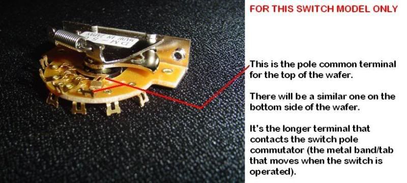
|
|
razbo
Apprentice Shielder
Posts: 36
Likes: 0
|
Post by razbo on Jun 12, 2009 6:29:35 GMT -5
Ok, here's what's up. I am in the process of working out a solution of my own. It's not going to be nearly so good as JohnH's, but me being me, I gotta do it.  No offense meant, so please do not take any, and I feel guilty not using it since you went thru that effort! I have complete faith in the diagram. (And anyway, it's inspirational. I never would have thought of trying to get more than basic wiring connected.) Time constraints are upon me so it will be another day or two couple hours before I can present it for "vetting". (Excellent suggestion, cynical1!) [Edit: Here it is. Please don't laugh at my drawing!  ] I will try the image tags again  Yay it worked! Grey wire is the Single Coil and Red is the HB. Forgot some labels: the top Round Thingy is Volume and bottom Round Thingy is Tone. The P/P I put off to the side to make it clearer. With this I should get, in SSS mode (P/P Up), all the typical Strat options. SC SC + M M SC + N N In HSS mode (P/P down) I should have the HB "on" all the time giving me HB HB + M HB + M HB + M + N HB + N ...Right? I have exclude some options not only for simplicity, but also to keep the options more standard to what I might find on a Fender off the shelf. (Except I don't think they wire their HSS like this.) I am wanting to get a sound fix on what I've done. Once I've established that, I can try enhancements and see if they actually enhance anything to my ears. |
|
|
|
Post by sumgai on Jun 12, 2009 12:11:34 GMT -5
razzer, You've drawn your push-pull switch a little.... different.  I'll assume for the moment that you mean 'when it's up, the grey wires are connected, and when it's down, the red wires are connected' - is that what you intended? If so, then your circuit is good to go. ;D Of course, which terminals of the switch you use are crucial to this plan (as is true in all diagrams!). Most push-pull switches use the arrangement of the center terminal on one side is connected to either the upper or lower terminal on the same side, depending on the switch handle's position. Given the above, you'll want to put the two pickup wires (grey and red) on the two center terminals, and the remaining wires will go to their respective sides, the grey on the upper terminal and the red on the lower terminal. Good luck! HTH sumgai |
|
razbo
Apprentice Shielder
Posts: 36
Likes: 0
|
Post by razbo on Jun 12, 2009 12:25:12 GMT -5
Yeah, sorry. High on my To Do list is getting new batteries for my meter, so I wasn't entirely sure how it linked up inside.
This is pretty basic stuff for you guys (or probably anybody), but I am proud I did not get lol'd off the board. ;D
|
|
|
|
Post by ChrisK on Jun 12, 2009 14:51:22 GMT -5
In Electronics Templates there is a diagram that shows the internal switching of a push pull pot. Your volume and tone pot terminal wiring is also reversed. Since you are showing the bottom view, the volume will be maximum at "0" and the tone cut will be minimum at "0". Swap the outside terminals on each. |
|
|
|
Post by JohnH on Jun 12, 2009 18:46:11 GMT -5
Yesterday at 22:29, razbo wrote:
No problem at all! I am truly delighted that you are having a go. Instead of providing some fish, it seems we may have created another fisherman!
It is much more educational and enjoyable to develop and build your own designs.
What you are drawing seems to me to be a very good design intent. There's a few less sounds than what I drew, but it is also simpler, easier to build and also to operate, which makes it a good simple design. You are still getting the essential extras of coil cut on the Hb, and some options with bridge and neck, out of the one switch. That puts it above what most standard diagrams will achieve. Also, the need for the clever switching of coils to keep humcancelling in Sc mode is avoided, since you don't combine bridge single coil with neck.
What Chris and Sumgai point out I agree with, so it would be a good idea to make the next diagram and repost it. Keep the old one there though - then the whole thread makes sense and it remains as a learning exercise for others who may follow you.
Ive just got a couple of further observations, wrt that StewMac 5-way. I think the way you have your lugs and wires laid out is right for that switch, if you shift the right side up and the left side down relative to each other, keeping the wires. Also, although you are connecting (with the red wire) to the pole on the right side, you are not really using that side of the switch, since the other lugs are not used. You could if you wish, miss out the wire diagonally across the switch and go just to the right side pole. Or, just use the left side and not the right side.
Just noticed another thing - you may be better to go straight from bridge pup red wire to the 5-way, and then use the pp switch to shunt the white wire to ground. That I think is nearer to how StewMac recommend it, to get the correct Hb coil working to combine with the middle.
Also, you have chosen that the Sc mode is with pp up. Thats fine, I think I would have it down though, since that is a more standard arrangement for the default position - but either is fine.
John
|
|
razbo
Apprentice Shielder
Posts: 36
Likes: 0
|
Post by razbo on Jun 12, 2009 20:37:26 GMT -5
Awesome. I'm just glad the friggin' thing would work. I got one up on EVH heheheh Regarding switch lugs, etc. I did a sketch in the workshop on a smoke break and didn't check it against anything for accuracy of lug locations. I should not be careless like that if I expect to communicate with anyone using diagrams! I will post a better one for posterity to contrast with my hasty effort. I'll check that out. One of the things I do not find intuitive for me in wiring is using the path of least resistance effectively. Yes I have. The way it will mostly be used is P/P down in HB mode, so I did it that way to avoid accidentally switching in the heat of the moment. Didn't see that one yet. Very handy, thanks! How do you know I'm nort left handed?  |
|
|
|
Post by sumgai on Jun 13, 2009 0:47:27 GMT -5
Chris, ......
Your volume and tone pot terminal wiring is also reversed. Since you are showing the bottom view, the volume will be maximum at "0" and the tone cut will be minimum at "0".
Swap the outside terminals on each. Errr, noch mal, bitte? I agree that razbo's Volume pot is reversed from standard, but his Tone control wiring looks correct to me. sumgai EDIT: Kicked out of the Department of Redundancy Department. |
|


 Nevertheless, I am making progress and I understand what you are saying and it sounds interesting.
 I just picked up electric guitar a few months ago, so I have no experience with different kinds of pick ups. I figured these could establish kind of a baseline for me to compare others with.


 ]
]
 I'll assume for the moment that you mean 'when it's up, the grey wires are connected, and when it's down, the red wires are connected' - is that what you intended? If so, then your circuit is good to go. ;D