|
|
Post by mojomonster on Nov 3, 2009 14:21:09 GMT -5
Hi guys, I'm hoping someone can help me out here. I'm not new to wiring pickups, but I have this propensity for biting off more than I can chew. What I'm trying to do is wire up a Strat using a set of Seymour Duncan Custom Shop StraBro90's, which are wound to sound similar to P90's but are coil tapped to sound like Strat singles, as well. I'm going from the pickups to individual push/push on/on DPDT switches(the "Jeff Beck" switch) to select either full or tapped and then to a 5-way Superswitch. I'd love to use Mike Richardson's superswitch wiring scheme, but... and here's where I leapt off the cliff... I want to wire this into the Clapton Mid Boost ( cracklecdn-zoovy-2.simplecdn.net/img/guitarelectronics/W628-H550-Bffffff/W/wdu_sss5l11_tbx2.jpg) board and pots.  Where I lose it is in connecting Mike's superswitch scheme to the board/TBX pot. The typical Boost diagram shows one connection point off of the switch wheras Mike's schematic has many connection points. Can I actually do this while retaining the complexity of Mike's switching scheme? Any help would be greatly appreciated. This is my very first Strat, btw, a part-o-caster using a very light ash body, a warmoth Pro 22-fret rosewood neck with Schaller staggered, locking tuners and a Callaham steel tremolo. I'm hoping to do a faded cherryburst on the body and a gun oil finish on the neck. Thanks MM |
|
|
|
Post by pete12345 on Nov 3, 2009 14:55:22 GMT -5
Simple- the wire going from the switch to the mid boost circuit on the diagram would normally go to the volume control. You need to do the same with the Mike Richardson circuit: the connections which would go to the volume control on a passive setup all go to the relevant connection on the mid boost circuit board.
|
|
|
|
Post by JohnH on Nov 3, 2009 14:58:43 GMT -5
agreed - it should work fine, and welcome to GN2.
With your coil tap push/pulls for each pickup, are you adding a further switch, maybe as a toggle, to do the series/parallel function?
John
|
|
|
|
Post by mojomonster on Nov 3, 2009 17:11:48 GMT -5
Thanks for the response guys, this means a lot. Simple- the wire going from the switch to the mid boost circuit on the diagram would normally go to the volume control. You need to do the same with the Mike Richardson circuit: the connections which would go to the volume control on a passive setup all go to the relevant connection on the mid boost circuit board. Am I running the volume out from the S/P switch and N+ directly to the volume connection or just one of those? (I'm assuming this is the connection just to the right of the ground wire on the board) So what would I hook up to the TBX? For the TBX to effect all 3 pickups would I connect the N+, M+ and B+ to the center TBX lug? And JohnH, yes, it's another of the "Jeff Beck" switches. I've also got another so I could, in the future, do the neck phase switch as well. Firsts things first, however.  MM |
|
|
|
Post by sumgai on Nov 3, 2009 18:01:22 GMT -5
John, This is a true single coil with a tap somewhere along its winding. You can't add or subtract coils, as there is only one coil. You select either the full or the tapped output wires, and that's it. Presumably, you could elect to use the "other" part of the tap (hot lead of "full" to hot lead of "tapped"), but that should result in a greatly reduced output. Duncan's website, even the Custom Shop portion, is woefully inadequate in describing any of their pickups properly, but on other websites, I found that the tap is supposed to be about 2/3 rds along the winding. Take that for what it's worth, I'm only parroting a bunch of Nutz-wannabe's (they aren't here, but they're trying real hard to imitate us!! ;D) ~!~!~!~!~!~ MM, Sorry, I'm a bit busy just now, but perhaps tonight I'll be able to sit down and draw a diagram. If not, then it'll be Thursday before I can do it. (The other half has plans/designs on my time, before she goes away for a long weekend.  ) BTW, I googled for your StraBro90, and I'm not sure if you know it or not, but nobody on the Internet, except the SDUGF, seems to know anything about it - especially the nice folks at Semour Duncan itself are pretending it doesn't exist!!!!! Care to share any ideas on how this could come to be?  Also, Google also found your Photobucket diagrams. Nice artwork, you should post some of it here in this thread, to give our members an idea of what you're after. And lest we forget it, Hi, and  to the NutzHouse! HTH sumgai |
|
|
|
Post by mojomonster on Nov 3, 2009 19:51:39 GMT -5
Hey, thanks. I've been a member of the Seymour Duncan User Group Forum(SDUGF) for a few years now and the StraBro90 is a "forum pickup"... the latest of 3 that were designed by the forumites(the Brobucker and the Crazy 8 were the other two) which is then offered for sale by SD's Custom Shop at a reduced cost for SDUGF members and CS prices for everyone else. I'm not sure of the exact specs right now, but I can find out. And, yea, as soon as I've got it working, I'll post some pics and drawings. Thanks again. MM |
|
|
|
Post by sumgai on Nov 4, 2009 0:55:21 GMT -5
MM, Yes, I got that part about the Forum members designing the pickjup(s), but how come the Custom Shop website doesn't show it for sale? The other two you mentioned are part of the catalog, only the StraBro90 is missing. Is it too new? Are the webmasters being lazy (or spiteful 'cause the didn't get any of the action  )? As to drawings.... You are certainly qualifed, I've see your work! But do you still need "help" or "guidance" in fitting the M.R. mod into your scheme? sumgai |
|
|
|
Post by mojomonster on Nov 4, 2009 10:10:54 GMT -5
MM, Yes, I got that part about the Forum members designing the pickjup(s), but how come the Custom Shop website doesn't show it for sale? The other two you mentioned are part of the catalog, only the StraBro90 is missing. Is it too new? Are the webmasters being lazy (or spiteful 'cause the didn't get any of the action )? No idea, really, sorry. They just updated their website design, so it may have fallen thru the cracks. I know they're really good about responding to phone calls. This is the original thread: www.seymourduncan.com/forum/showthread.php?t=142571&highlight=strabro90This is what it looks like(its upside down... the slugs go on EA&D, the screws on GB&E): i426.photobucket.com/albums/pp349/MaricelaJuarez/P1020731-1.jpgSpecs I could find in the forum: Official specs: Neck 7.5 K and 15.7K Middle 7.9k and 16 k Bridge 8.8k and 17.9k What one forumite measured: Neck - 7.4K tapped / 14.6K full Middle - 7.5K tapped / 14.4K full Mine: Neck: 7.35k tapped /14.88k full Middle RWRP: 7.38k tapped /14.74k full Bridge: 8.47k tapped /16.53k full You can tell they used a thicker wire at some point in the wind because the bobbins are *full*. I had to sand out the pickup openings on my pickguard a bit for them to fit thru. Thanks. I've not put solder to iron yet, as I want to be as certain as possible that what I'm doing is accurate and correct, so yes, any clarification would be helpful. Pete's post was helpful, but as you can see I had some other questions. I've realized that for all intents and purposes, the EC Boost is wired master volume/master tone. I think it would be useful to see MRs mod wired this way, even without the EC Boost to complicate things. Thanks MM |
|
|
|
Post by sumgai on Nov 4, 2009 15:00:54 GMT -5
MM, OK I, missed my opportunity to make/post a drawing, so it'll have to wait till tomorrow (Thursday afternoon or so). I'll read back through all you've said here, and try to cover all the bases. Hang tight! As to your measurements, it looks more like a 50/50 percentage than a 2/3 rds tap. But that's a measurement of a static condition (Ohms of resistance to DC), it doesn't tell us how much wire of each gauge was wound on the bobbin. Since we're talking about different wire gauges, I might be tempted to jury-rig a pair of wires from both "hot" leads, just to see if it sounded different (better? worse?) than the normal tap connections. Oh, and I didn't know about the Custom Shop's website redesign, so it might be nothing more than a simple "fell through the cracks" issue, you're correct. And while I'm at it, can you perhaps record some of these tones, when you're done? We have a sound sample Forum, just like the one for images. Or you can post them here in this thread, if you like. sumgai |
|
|
|
Post by mojomonster on Nov 8, 2009 20:43:14 GMT -5
|
|
|
|
Post by sumgai on Nov 9, 2009 0:27:54 GMT -5
Hmmmm..... I've never vetted any of ChrisK's drawings before. Probably should have by now.  John, I don't see any output from the ser/par switch in the serial position. The volume control get its input on the standard terminal we'd expect. That terminal is fed directly from the ser/par switch, and as I perceive it, only from said switch - no other connections are made, excepting the usual tone control. As I see it, and as I understand logic flow, when the switch is down, signals flow as normal. But when the switch is up, where's the continuity that would present a signal to the volume control?  After all this time, am I the last one to the party, the one where Chris introduced his new "signal flow without wires" concept, no doubt using some of his hidden stock of Unobtainium?   As Chris tells us the he's built this in his Padouk Caster, I now suspect that he "forgot" to make an edit whereby the circuit was made to work on the guitar, but not on paper. I hope.... sumgai |
|
|
|
Post by JohnH on Nov 9, 2009 3:38:10 GMT -5
Sumgai - the version I posted, based on Chris' design seems to trace out OK, and it has already been built yesterday by our new friend Jon in Melbourne - just a few hundred miles from here. (Australia: a 'get-it-done' kind of continent, while the world sleeps - we rewire our guitars!....)
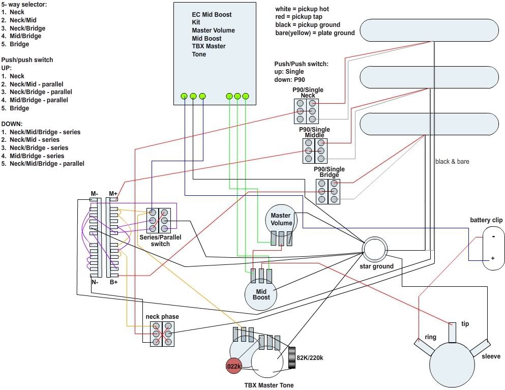
On momjomonsters version, the core of it seems OK to me, except for the diagonal wire on the series parallel switch, which should go to the lower left not the centre left lug. At the S/P switch, the pickup signal leaves from the top left lug and disappears into the EC booster, after which I dont know how it should be wired.
Also, there are two versions of single/P90 switching shown, and I don't know which one is best.
regards
John
|
|
|
|
Post by mojomonster on Nov 9, 2009 10:28:31 GMT -5
Thanks for the look see John. Those were mistakes. It will be updated soon. Image is now fixed. The diagram I'm using to decipher the EC Boost kit is here:  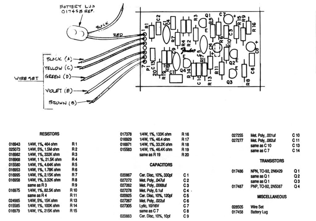 Thanks again. MM |
|
|
|
Post by sumgai on Nov 9, 2009 14:48:06 GMT -5
John, Got it! I temporarily went color blind, and missed the light beige wire from M+(A) directly to the volume control - to my eyes, the red wire to the tone control was hiding the final silly millimeter. Mea culpa!  sumgai |
|
|
|
Post by sumgai on Nov 9, 2009 15:01:09 GMT -5
MM, About those two versions of the P90/SC switch wiring, as mentioned by JohnH..... I'd choose the way you've shown for the Bridge pup. Reason being, you're shorting the second (outer) coil, thus you avoid any potential issues with what we call "a hanging hot ". That's where a coil is connected to a hot lead, but not grounded. In itself it won't pickup and send out magnetic impulses from the strings, but it can (as in, it might, not that it defintely will) act as an antenna for stray RF, EMI, EMP, and other sorts of objectionable interference. Selecting one coil or the other (as in the Neck and Middle switches) presents the issue, shorting the outer coil kills all possibility of the issue. Your call. Oh, and I should mention that what I'm suggesting reverses the action of the switch. You'll need to select the correct terminals to connect in order to get the desired physical action during operation/playing. sumgai |
|
|
|
Post by mojomonster on Nov 9, 2009 16:40:24 GMT -5
MM, About those two versions of the P90/SC switch wiring, as mentioned by JohnH..... I'd choose the way you've shown for the Bridge pup. Reason being, you're shorting the second (outer) coil, thus you avoid any potential issues with what we call "a hanging hot ". That's where a coil is connected to a hot lead, but not grounded. In itself it won't pickup and send out magnetic impulses from the strings, but it can (as in, it might, not that it defintely will) act as an antenna for stray RF, EMI, EMP, and other sorts of objectionable interference. Selecting one coil or the other (as in the Neck and Middle switches) presents the issue, shorting the outer coil kills all possibility of the issue. Your call. Oh, and I should mention that what I'm suggesting reverses the action of the switch. You'll need to select the correct terminals to connect in order to get the desired physical action during operation/playing. sumgai Ok, I think I understand what you're saying. I want the pickup to be tapped in the up position and the full coil in the down position. So should I move the red wire to the lower lug and leave the white wire in the center lug? MM |
|
|
|
Post by sumgai on Nov 9, 2009 18:56:08 GMT -5
Ok, I think I understand what you're saying.
I want the pickup to be tapped in the up position and the full coil in the down position. So should I move the red wire to the lower lug and leave the white wire in the center lug? Choosing the upper or lower terminal will depend on how the switch was built. Rather than give you a bunch of possibilities, why don't you take your digital multimeter to the thing, and check it for yourself? The action you're looking for is: when the switch is shorting the outer winding, you get only the tapped output. When the outer coil is unshorted, you get the full output. The color coding you just asked about is correct, according to your chart. Red (tapped) will go to the chosen terminal (be it upper or lower, as revealed by testing with a meter), and White (full output) will go to the center terminal. HTH sumgai |
|
|
|
Post by mojomonster on Nov 9, 2009 20:19:23 GMT -5
Most excellent.
I'll let you guys know how it worked out.
Thanks
MM
|
|


 )
)


 As Chris tells us the he's built this in his Padouk Caster, I now suspect that he "forgot" to make an edit whereby the circuit was made to work on the guitar, but not on paper. I hope....