ivo215
Rookie Solder Flinger

Posts: 21
Likes: 0
|
Post by ivo215 on Nov 25, 2010 16:19:26 GMT -5
Last february I loaded my strat with 3 Duncan humbucking pickups, a 5-way superswitch and 3 push-pulls. The result was a strat with 24 possible combinations. But they aren't really in a very logical order. And the tone pots aren't wired optimal. So I've been breaking my head over everything-strat v2.0 Mostly for the hell of it, not because I need more sounds. It's a challenge thing. First of all, the rules: No holes in the pickguard for extra switches. No routing the body for more space. I came up with a scheme for 28 different possible combinations, and they're quite logical. And the tone knobs work very well with that too. But I can't seem to get all the desired functions out of a single 5-way superswitch and the 3 push-pulls. So I started playing with the idea to get 2 of these:  and splice them together, making a 48-lug 5-way switch. But even that doesn't allow all of the possibilities I want to cram in there. And with a hypothetical 72 lug switch my head starts to ache and I get lost in my own wiring scheme. So now I'm thinking about doing it different. I'm thinking about a phone battery (nice and flat) in the tremolo-spring compartment to power a bunch of relais. And i found these tiny little Fujitsu relays online. So now I've got a plan with a single 5-way super switch, 3 push-pulls and a cluster of 23 of these little relays, that gives all the functions I want. And when I select the bridge all the relais will be in their resting-position, so the battery wont die on me. But when selecting the middle and neck pu in parallel, this contraption will drain a whopping 600mA. That'll suck the battery dry in no time at all. I could lower the max consumption to about 400mA by using solid state relays for the bits that aren't in the signal path. But that would take up more room (need a lot more of them, the relays are dpdt, ssr's aren't) so it probably won't fit inside the guitar. It's also more expensive. So right now I'm at a dead end and I'm dying for ideas. Maybe I haven't found the right relays yet. These have a 140mW coil. In case you're wondering about all the functions I want to cram in to the guitar: Position 1. Selects the bridge pickup. Tone 1 does the tone. The Push-pull under tone 1 switches the pickup from series wiring to parallel.
Positions 2,3 and 4. Selects bridge&mid, bridge&neck, mid&neck.
The push-pull under tone 1 switches the bridge-most selected pickup from series to parallel. The push-pull under tone 2 does the same for the neck most selected pickup.
The push-pull under the volume knob switches both selected pickups in series or in parallel of eachother.
When the volume push-pull is in parallel mode, tone 1 works on position 2, tone 2 on positions 3 and 4. When the volume push-pull is in series mode, tone 1 does the tone for the bridge-most selected pickup, and tone 2 the neck-most selected pickup.
Position 5 selects the neck pickup. Tone 2 does the tone. The push-pull under tone 2 does the series/parallel switching. |
|
|
|
Post by newey on Nov 25, 2010 21:05:20 GMT -5
ivo215-
Hello and Welcome to G-Nutz2!
I'm having trouble wrapping my head around 23 relays. Do you have a schematic?
We've discussed the use of relays to control switching before, although as far as I know, no members have ever actually done anything along those lines. So, we'd love to see what you have planned here.
Some have questioned whether using electromechanical relays might cause noise issues. Ashcatlt said he didn't think it was an issue, since the relays are powered by DC. I'm not so sure. They might not directly introduce noise into the signal line, but I wonder about indirect noise, via the pickups. SS relays would presumably solve that concern.
We have also speculated about (but not built, AFAIK) the use of digital control to switch analog guitar functions. As opposed to 23 relays, this might be better done digitally . . . Food for thought, anyway.
|
|
|
|
Post by JohnH on Nov 25, 2010 23:07:25 GMT -5
Good luck figuring out 23 relays!
But if you decide to step back a pace, I’d be inclined to go a lot simpler, and get 90% of the versatility for 20% of the wiring effort, and no relays. My suggestion would be:
A 5-way super switch, to give the pickup combos that you have chosen
Let the tone1 operate just on the bridge, and let the tone2 work only with the neck, ie, the tone pots are hard wired to these pickups.
When you mix parallel and series wired pickups, in a parallel combination, the parallel sound will dominate, since it is much lower impedance. Also, personally, I really like single coil sounds, particularly on the neck. And with single coil cuts, only one pole is needed. So, you could have the p/p switch on tone 1 make bridge coils in parallel, and on tone 2, make both middle and neck pups cut to single coils.
The p/p switch on the volume pot does overall series/parallel, as you intended
24 sounds at first count, plus tone variations. You miss out on some M/N combos, and not quite as much tone control subtlety.
What do you think?
John
|
|
ivo215
Rookie Solder Flinger
Posts: 21
Likes: 0
|
Post by ivo215 on Nov 26, 2010 13:57:07 GMT -5
@ JohnH:
That's about-ish what I've got now.
Right now the t1-p/p switches the bridge pu from series to parallel, and the vol-p/p does the same for the neck pickup.
The 5-way is wired B, B^M, M, M^N, N.
And pulling the t2-p/p will alter the 5-way's wiring to B^N, B+M, B^M^N, M+N, B+N
(+=parallel, ^=series)
@ Newey:
Yeah, 23 relays is way over the top. I don't have a fully worked out post-able out schematic, just a lot of doodling on paper with a lot of stuff crossed out.
So 23 relays just wont do. I've been going over it in my head all day today.
I went back to the previous idea of splicing several super 5-way's together.
When I got home just now I started doodling again, and figured out how to do all the switching without any relays, but with 4 of these super 5-ways gleud together as 1 massive 96-lug 5-way switch. It went surprisingly easy this time. Probably because I've gotten close to this schematic a few times before.
But I don't think 4 of these will fit inside the strat. So I started crossing stuff out again and came up with 3 of these switches together (72 lugs), and using 2 of those Fujitsu mini dpdt relays.
A 72 lug switch might just fit. And 2 relays will draw a max current of just below 80mA. And selecting the bridge pu will use no power at all, so the battery won't die when I'm not using the guitar.
Using a 900mAh phone battery that's 11+ hours minimum battery life. I've been crossing out ideas for 2 weeks now, and this is the first time it looks do-able.
I just depends on that Göldo switch. Can more of them be spliced together?
I'll try to do some neater doodling without so much crossing out, scan it and post it.
If I'd go for SSR's instead of those 2 relays, the current will be between 3 and 10 mA. So the battery life will improve enormeously. But there will be no true off-position.
|
|
ivo215
Rookie Solder Flinger
Posts: 21
Likes: 0
|
Post by ivo215 on Nov 26, 2010 15:44:40 GMT -5
Right, this is where I'm at now:  I didn't bother drawing the battery, or the output socket, or most of the wires for that matter. Just the coils, the switches, the pots and both relays. Instead of drawing the wires, I used letters to show what goes where. And I did do some crossing out because I noticed I had forgotten something. But no biggy. At the top, there's the 6 coils from the 3 humbuckers. I'm planning on Duncans, so I referred to Duncan wire colours. BB is bridge black, NR is neck red, etc. Then there's 3 super 5-ways next to eachother. The first 2 connect all the pickup wires to the 2 tone push/pulls. Below those are the 3 push/pulls. Tone 1 and 2 p/p switch their respective humbucker from series to parallel. Down is series. The volume push/pull puts the 2 selected pickups in series or in parallel. It sends the battery power to 3 of the 4 remaining rows of 5-way lugs, on the 3rd 5-way switch. P for parallel, S for series. It also connects the bottom end of the tone 2 pot either to the negative of the second selected pu, or to ground. PR (parallel relay) does the actual switching of the 2 selected pickups. When the relay isn't powered they're in series. When the relay gets power it switches them parallel. TR (tone relay) cuts off T1 and connects T2 when powered. So in positions 3~4, when in parallel mode, T2 takes over from T1. And in pos 5, T2 also takes over from T1, regardless of the volume push/pull. Long story short, there's 28 permutations. Pull a push/pull and the guitar will sound brighter and lighter. Push it back down and it gets darker and more powerfull. |
|
ivo215
Rookie Solder Flinger
Posts: 21
Likes: 0
|
Post by ivo215 on Nov 26, 2010 15:57:13 GMT -5
And I could do without another lane of 5-way. The S-lane can be crossed out. Instead putting a +3.6V connection on the position 5 lug of the left P lane.
The S on the volume P/P can then be crossed out too.
But it doesn't matter really if I'm using 2½ super 5-ways or 2¾, I still need 3 of them.
In the 23 relay scheme, I used only a single super 5-way switch.
I used relays to do all the pickup selecting (that's 8 of them right there). Selecting tone knobs, 2 relays. Switching from parallel to series, 1 relay. Bypassing the un-used p/p in positions 1 and 5, 2 more relays.
And 7 more relays to select groups of relays, depending on the positions of the 5-way and the volume p/p.
That's 22. The 23rd was in a previous attempt which I crossed out.
|
|
|
|
Post by newey on Nov 26, 2010 16:37:00 GMT -5
Ok, still trying to follow your diagram. Not saying it won't work, so far what I see seems all right.
But earlier on, you said:
How do you plan to "gang" the three levers into one? And will it fit without routing the side of the cavity to accommodate the extra width?
JohnH suggested a simplified version without the need for a battery, relays, etc. Another idea along those lines would be to use a pair of the SD "Triple Shot" pickup rings for the N and Br HBs. These have little slide switches on the ring itself to give the HB coils in parallel, series, or either single coil individually. Using those to do your "intra-pickup" switching frees up 2 p/ps for other uses, such as selecting your tone pots as you have the relays doing.
If the goal is the maximum number of combos (without extra holes), you could wire the 5-way to just control the N and Br pickups (This can be done so as to give N and Br OOP in one position, for a total of 5 distinct settings).
Then use one p/p to turn the middle on/off. With 2 p/ps giving the neck in series/parallel, and same for the bridge, I count 15 permutations of the 5-way with the N and Br p/ps, and double that number with the mid on, for a total of 30. Of course, this doesn't select the tone controls. But a whole lot simpler . . .
You could also use all three pots as individual tone controls, and move the volume function off the guitar to a volume pedal.
|
|
|
|
Post by sumgai on Nov 26, 2010 16:46:48 GMT -5
Not for the first time have I wished that ChrisK were still with us!  ~~~~~~~~~~~~~~~~~~~~~~~~~~~ ivo, Hi, and  to the NutzHouse! I've got one word for you: 4066Now if that's got your attention like I think it should, then let Google do the walking: Reaching out and touching a 4066Try it, you'll like it! ;D HTH sumgai
|
|
ivo215
Rookie Solder Flinger
Posts: 21
Likes: 0
|
Post by ivo215 on Nov 26, 2010 17:20:09 GMT -5
@ newey:
Hi,
I don't want 3 5-way levers sticking out of the pickguard.
I'll cut 2 of them off and fix the 3 switches together. So the 1 lever sticking out is switching all 3 switches simultaniously.
These Göldo's are screwed together, and so it might be possible to DIY them together into 1 switch. Also they're quite narrow. So 3 of them side by side should just go, there should be just enough space between the switch and the volume and tone 2 pots ... I hope.
@ Sumgai
Yep, I found the 4066 a while back.
I was halfway of making a wiring scheme with those when I decided that relays with gold plated electrodes would be better. This because all the effects guys are always going on about how all their pedals have to be true bypass nowadays. I'm kind of worried the 4066 will colour the sound.
Also I couldn't make a 4066 wiring scheme with a true off position, when there's no power drawn from the battery. And I do want that.
If the sound colouring is not an issue, a single super 5-way switch would suffice, with a combination of 3 relays (for the true-off bit battery life thing) and couple of 4066 IC's
I guess I'll get doodling again ...
I haven't used IC's in an audio path before. So if anyone can vouch for the 4066 not colouring the sound (much), this might just be a better approach than a 72 lug 5-way switch.
By the way, I have looked in to IC's and I think Panasonic should make a photoMOS version of the 4066. The photoMOS has a much lower on-resistance, and a much lower capacitance than a normal 4066. Like, near tenfold lower.
Hmmm, fix it with digital pots, IC variable resistors, a memorybank and a processor, you could have a thousand permutations and store them as presets. That'll be everythingstrat v3.0, for some other time and some other strat.
|
|
ivo215
Rookie Solder Flinger
Posts: 21
Likes: 0
|
Post by ivo215 on Nov 26, 2010 20:59:46 GMT -5
Just finished the first draft of a 4066 scheme.
Looks like it could be realised with a single super 5-way, 3 push/pulls, 3 mini dpdt relays, 11 4066 IC's and 5 diodes. 11 IC's will fit, I thibk. I could stick them to the back side of the pickguard with double sided sticky tape. And I could stack them.
1 IC has 4 On-Off's. I need 44 a total of On-Off's, so 11 IC's.
When an On-Off goes unused, it's gate lug must be connected to ground.
19 on-offs are used for the actual switching.
17 are used to switch on groups of other on-offs.
8 are used to ground unused on-offs or groups of on-offs.
I haven't checked if everything's working correctly, so I'm not posting it just yet.
And maybe I can streamline it some more, to lessen the number of on-offs used.
Anyway, it's way too late. I need some sleep right now.
|
|
|
|
Post by 4real on Nov 27, 2010 17:00:53 GMT -5
Can't quite see how you are going to fit all these ganged 5ways or other stuff into the guitar control cavity without making more room  I'd also be concerned about having active switching in the guitar like that...so the thing is not functional when the battery dies...but that might just be me. You might want to think hard about the scuttlebutt of 'stompbox' geeks...while true bypass might be advantageous, may subscribe to adding a preamp to alleviate the tone loss through any guitar cable...so the opposite philosophy for improved "tone"... But a challenge is a challenge. I like the idea of the 'triple shot' rings to take over a lot of the functions as one approach. But beware...I still have yet to make any sense of my strats wiring...my next project...again! I like the idea of making some unique components...for instance the "uber pots" is one approach... 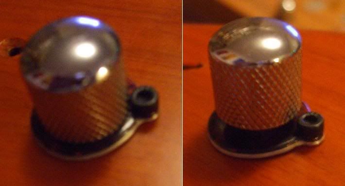 Kind of based on a car radio control...each pot is a dpdt push-pull and a dual gang pot...the 'ring' at the base is a two position 4pdt switch in addition (although I suppose it could be modified to three positions with some tinkering. Inside I used two mini dpdt toggle switches at are activated together by a plate... 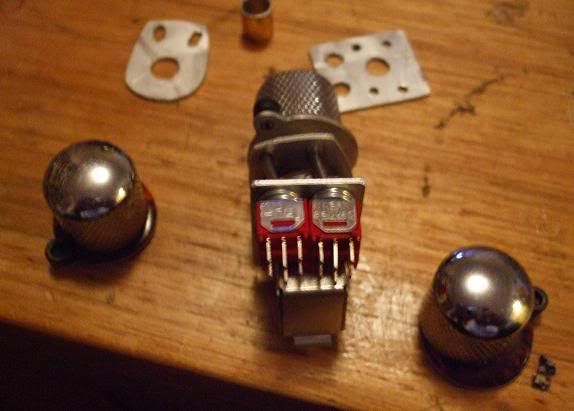 I also fitted the thing with a superswitch selector... however, the result is a very tight and complicated mess that two years later still looks like this!!! 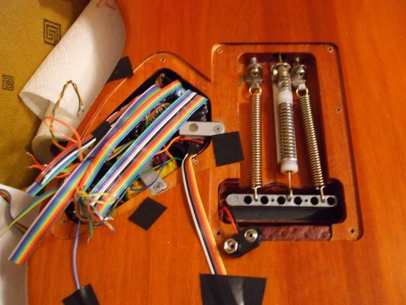 So I guess one has to be careful what one wishes for. Still...a lot of switching power with no hole drilling. I was concerned with this guitar because it is a clean back cavity thing with no scratch plate. However, if it weren't for that, I probably would add switches as required in a replacement plate should I want it to return to stock later perhaps. Other options might be some giant multi ganged rotary switch in place of a tone control...again, not sure how you'd fit all this in without any modification inside the guitar. My ambition was to do with the sustainer to get the switching power required into a 'single control'...so, turn the base to switch on and bypass to the bridge pickup, pull the knob for harmonic drive, turn the pot for amount of drive...and this was achieved. But I fear I got carried away there buy doing it to all three controls...LOL...and adding more and more options... Now I am thinking...hmm...i think I just want the bridge HB to be series and parallel...that only requires a dpdt switch...and a phase switch perhaps...maybe a...oh, it's so easy to get carried away! But modifying a guitar is not that much of a sin and can be done without changing too much of the appearance especially on a strat with such a huge scratchplate and already essentially hollow. As long as the structural integrity isn't compromised. On this guitar you can see I needed somewhere to hide the battery so I made a tricky route behind the trem block into the back of the guitar. On other guitars I have put switches into the lower horn out of the way of the strumming hand, you could put something higher up in a more jazzmaster kind of way perhaps. I don't think that you are going to get any coloration using 4066's as these are really only switches triggered by power and at least are compact. If you were truely nuts, you could add a sequencer chip in there too and a randomizer so that it randomly swithces between all the selections to create some weird stuttering pickup selecting filter effect...LOL It's probably sacrilege here, but there is such a thing as too many options and wiring yourself into a nightmare as with my example. In reality, how many options do you really need that sound significantly different and worth the effort. Once you go down the route of an active guitar, you would get far more dramatic effects perhaps from active EQ tone controls and preamps that would draw far less current...and then just basic passive pickup selection switching to choice...and a 'passive mode' switch for when your battery inevitably dies... |
|
|
|
Post by JohnH on Nov 27, 2010 17:17:39 GMT -5
hmm..looking at what sumgai linked to, the 4066, it could be quite handy for this sort of thing. Looking at the spec sheets, the 'on' resistance is listed as 80Ohms. so provided you dont have too many of those in series, it should be low enough not to matter. Current draw is also tiny. So the challenge is to see how few you need to do what you wish. I'd suggest getting a very simple switching design to work first, just to check that it will all function
|
|
ivo215
Rookie Solder Flinger
Posts: 21
Likes: 0
|
Post by ivo215 on Nov 28, 2010 8:09:19 GMT -5
So I've been puzzeling at this all day yesterday,
I had a scheme for a quadruple 5-way, and no active switching.
Or a triple 5-way and 2 relays.
And a scheme for a single 5-way with 11 4066 chips (44 on/off switches) and 3 relays.
The trouble with the 4066's is that when an on/off isn't used, it must be grounded. So I'm using more and more on/off's to ground other unused ones.
This time I went for a double super 5-way approach. It should fit easy. I put the 3 relays in the scheme for the true-off bit to save battery life, and started doodling.
At first I was at 17 4066 on/off's (4.25 chips), but then found I could do it more efficiently and could cross a couple out. Then the ones that were supposed to ground them when unused were no longer needed and could be crossed out. Which freed up space on the 5-way, so I could move some 4066 functions to the 5-way, which led to more crossing out of the 4066 chips.
It was like solving a puzzle near the end where everything just seems to effortlessly fall in place.
So finally after re-re-redesigning the scheme I've been able to cross all of the 4066 bits, leaving just a single diode to be added to route the power for the active switching.
So I'm now at a double super 5-way. 3 push/pulls, 3 dpdt relays and 1 diode for the 28 options strat. That seems very doable to me.
I still have to double-check if everything works as supposed to, and that there aren't any unwanted connections (or shorts) possible in the switching.
The drawn current will be reasonably small, as there are only 3 relays, and they're not always on.
I guess the next step is ordering 2 of those Göldo switches and to see if I can DIY them into one, with a single lever. If I can do that, it looks like I'm in business.
I should also figure out a way to charge the battery without having to take it out. Which would mean putting a phone charger port and a charging circuit in the back I guess.
|
|
ivo215
Rookie Solder Flinger
Posts: 21
Likes: 0
|
Post by ivo215 on Nov 28, 2010 8:58:22 GMT -5
Here it is. Bear in mind, I haven't double-checked this one yet, it may still contain faults.  The reason why I keep favouring relays over IC's is because the IC's need power all the time in order to work. The relays only need power half the time, so there's no need for an extra on/off switch. Also because the 4066 chips need to have their unused on/off's grounded makes them more complex to use. By the way, I love the Über-pots, those are nice ! |
|
|
|
Post by 4real on Nov 28, 2010 14:28:26 GMT -5
I like the idea of chaining the switches together for some reason...but is this not exactly what a superswitch is?...  www.stewmac.com/shop/Electronics www.stewmac.com/shop/Electronics,_pickups/Components:_Switches_and_knobs/Super_Switch.html Might be easier and more reliable...just a thought. It all seems functionally not that much more than what you could do with a super switch and push pulls except that it changes tone controls around with selections...or so it seems...maybe I am missing something In the similar kind of thing I was looking for, everyone pointed me towards this scheme... guitarnuts2.proboards.com/index.cgi?board=schem&action=display&thread=3140which perhaps has 35 options and completely passive...it does include a single dpdt toggle for series parallel mode but also has a phase switch...so if you lost that, you could use that push-pull for that function and look 'stock'... I'm not sure how mine will end up...I really want it back together...I suspect I will attempt to do it in modules to get it moving along and evaluate sounds. Phase switches can be fun and I had 3 on an old strat and it had the unexpected result of 'reversing' the faux-reverse-phase kind of effect of combining the middle and bridge or neck to give a warm midrangy sound...the reverse of quack! But...if you really must, you must... They used to make an LED lit active switching selector called something like the "star-switch" though I can't find it now... For further ideas you could look at the ideas on DBG studios to see if there is anything else of interest or passive solutions... www.geocities.jp/dgb_studio/index_e.htmI think you are right to be concerned that it not go dead with the battery dying...but if you have something that is really low in draw using 4066's and an "off" when you unplug it...and you unplug the guitar...it would likely run for months much like a tiny active system. Not sure what the problem is with grounding the 4066's...they would be grounded to the battery's -ve terminal. However, with any of these ideas, you would need to test the devices, even relays, to ensure there is no switching noise. Remember that a relay has a coil through it and produce EMI that could easily be "picked up" by the sensitive sensor like a guitar pickup coil...wouldn't want to go to such extremes only to find the thing clicks and pops! I recently read in the old Adrian Legg book on wiring the idea he had in his old active guitars...a mercury switch...basically when the guitar is upright (as on a guitar stand) it would turn off the power...just another thought for power saving. Certainly it is not going to be as bad as most commercial sustainer systems which pull a lot of power and might have a max life of 20 hours and requires a battery for the active neck pickup and electronic switching a bit like this...that was something that I always aimed to avoid in my own guitars. Another thought comes to mind... Although you may want the guitar to look 'stock'...not sure entirely why it needs to go this way or how you will fit it all in to an unmodified strat effectively....have you considered perhaps some discrete 'slide' switches on the back plate (say the trem spring plate) along with the superswitch and push pulls...JohnH used something like this on the back on one of his LP schemes...and aiming for a completely passive scheme? |
|
|
|
Post by JohnH on Nov 28, 2010 14:58:31 GMT -5
Using relays for switching is a bit clunky, and there is likley to be a pop induced in the pickups when they switch. Relays are what they used for computing before they used tubes! The 4066's seem a more elegant concept, and soemthing new.
Are you sure there are no schemes that can be derived with passive switching? I can think of couple with HHH pickups and 5-way superswitches, though not exactly per your intentions.
cheers
John
|
|
ivo215
Rookie Solder Flinger
Posts: 21
Likes: 0
|
Post by ivo215 on Nov 28, 2010 15:26:36 GMT -5
@ 4real, The super 5-way is exactly what I'm after, only not with 2 wafers, but more of them. The wiring sheme you linked to is very similar to what I already have in my strat (mine has 24 positions right now, but with a not very logical switching layout, and the tone knobs aren't wired the way I'd like them to be. I wish to improve on that. JohnHNo, I'm not sure I can't do this with 100% passive. So I'm going to do even more doodling and more crossing out. I have been able to condens it all down to a double super 5-way, 3 relays and a diode. If I'd ditch the active switching, I might be able to get it all on a triple super 5-way without any active switching. So I'm going to work on that idea for a bit. |
|
ivo215
Rookie Solder Flinger
Posts: 21
Likes: 0
|
Post by ivo215 on Nov 28, 2010 16:09:12 GMT -5
I do believe I'm getting better at this. Here it is again, no active switching, with a triple 5-way. I don't think I could condense it down much further. Not down to a double super 5-way anyways.  I'm quite happy with this one. No more active switching, no more batteries, no more relays or IC's and a triple Göldo super 5-way might just fit. It seems so simple now that I've been at this for so long. I had a 23-relay scheme just a short while ago ... I guess I'll order those switches now, and try to DIY them into one. Though an active switching guitar would be kind of cool, just for the hell of it. |
|
|
|
Post by 4real on Nov 28, 2010 17:43:09 GMT -5
Can't check the wiring...but this seems to be a much better solution and keen to see how you tie all the switches together mechanically onto the single lever action...could be onto a winner
|
|
|
|
Post by JohnH on Nov 28, 2010 18:42:44 GMT -5
The thrill of these schemes is in the chase! And as a bonus, you may get a cool guitar out of it at the end.
A couple more points: If you do have anything active, the usual way to engage power is by using a stereo jack socket, and connecting battery negative to the ring terminal. Then when you push in a standard mono plug, it connects the battery to ground and current flows – so no extra switch needed.
Back on passive switching, the schemes I have in my head for HHH are based on the idea that the best sounds come when not all the coils are engaged, rather no more than two pickups at a time (or in one case, just two coils out of 6). This thinking applies also to your design, where you only use two of the pickups at a time. So a good use of a single 4 pole 5 way switch is to use it to select two pickups, ie two poles pick ground and hot connections for one pup (any one) and the other two poles do ground and hot with a second pup.
I also think that combining pickups that are wired differently to each other tends to be a bit subtle, and not very interesting, ie, a full HB mixes well with another, but mixing a parallel with a series connected one will sound very much like one of them.
I’ve found four ways to wire an Hb which I like, being the usual series, parallel, single coil, plus series with one coil bypassed by a cap, which is particularly nice at the bridge.
My uber-response to HHH on a Strat, with 56 sounds, would have a 5-way superswitch to select B, BM, BN, MN, N, a 6 pole 4 way rotary (replacing a pot), to convert all three pups between those four sounds ($6 from mouser), a master volume and tone, with push/pulls to do series/parallel and phase. It would still look like a Strat, (despite the rats nest inside it!)
Just floating that for interest, please carry on....
John
|
|
ivo215
Rookie Solder Flinger
Posts: 21
Likes: 0
|
Post by ivo215 on Nov 28, 2010 20:00:31 GMT -5
I just placed an order for 3 of those Göldo switches at musicstore.com.
I guess in a couple days I'll show the results (if they're positive).
Good one about the stereo jack socket. I don't know why I didn't think about that. I've been soldering wires to one in a friends Rickenbacker only a few weeks back.
The wiring scheme my strat has now has kind of prepared me for the sound possibilities.
And the ones I've chosen for this wiring scheme are really what I like the best from this particular guitar. In another guitar this scheme might be a lesser choice. But I think for my strat, and for the sounds I like, this'll be a good one.
One sound I particularly like is this:
Bridge pickup switched parallel, parallel to the neck pickup switched in series. This gives a very particular hollow sound. (It gets even better when you dial the tone back)
The bridge is bright and trebly in parallel, and the neck warm and creamy in series.
I guess your bridge humbucker in series with 1 coil capped will do something similar. 1 coil will give a bright sound, the other a dark one.
|
|
|
|
Post by JFrankParnell on Nov 28, 2010 22:37:17 GMT -5
|
|
|
|
Post by newey on Nov 28, 2010 23:32:44 GMT -5
Good find, jfp! +1! A 48-terminal, 8-pole MegaSwitch? Or, perhaps more, even? MUAHAHA!  |
|
|
|
Post by gumbo on Nov 29, 2010 5:38:23 GMT -5
JFP.... ...on looking at that old post, and the pics therein, is there some reason why the eyb 'stacked' version has to have that precise gap between the circuit boards...or is just some kid of 'modular' thinking that's gone on there??? ...in other words, could the judicious use of a Dremel and other sundry Implements Of Destruction reduce the overall width...?? Ozthoughtz........ |
|
|
|
Post by JFrankParnell on Nov 29, 2010 11:33:24 GMT -5
JFP.... ...on looking at that old post, and the pics therein, is there some reason why the eyb 'stacked' version has to have that precise gap between the circuit boards...or is just some kid of 'modular' thinking that's gone on there??? ...in other words, could the judicious use of a Dremel and other sundry Implements Of Destruction reduce the overall width...?? Ozthoughtz........ I just measured, you could skinny it up by 3-4mm by shortening the stand-offs and the square key in the middle. |
|
ivo215
Rookie Solder Flinger
Posts: 21
Likes: 0
|
Post by ivo215 on Nov 29, 2010 12:54:18 GMT -5
That's what I'm talking about ! And with a ruler, that's very handy info. 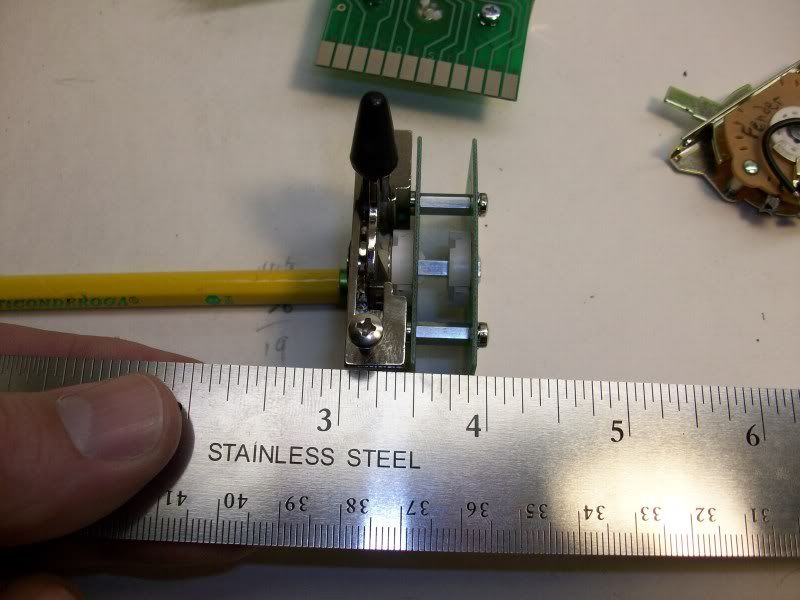 He seems to have used 10mm PC-board risers, and that's fine for a double. But for a triple that won't go. There is enough room between the switch and the volume pot, but between the switch and the tone2 pot it's too tight. But there's 5mm ones available too. And it should just fit with the lower risers. In fact, I think I've got a box of various PC screws and risers somewhere, I'll go look for that. What I'm more curious about is what he used for the axle and how it's connected. |
|
|
|
Post by JFrankParnell on Nov 29, 2010 13:53:06 GMT -5
|
|
ivo215
Rookie Solder Flinger
Posts: 21
Likes: 0
|
Post by ivo215 on Nov 29, 2010 22:13:11 GMT -5
Several people said they couldn't follow my scheme, and that's probably because it isn't very conventional. As it'll be a rat's nest when it's made, it's also going to be a rat's nest on paper. So I don't bother drawing wire connections much, instead I mark the lugs with corresponding letters. Here's the scheme again, only I added in the coils, the 5-way positions along side the 5-way switch and some scribles to try and make it clearer.  Let's give a little walkthrough here. Let's put the 5-way on position 2. A through H connect the first 2 5-way switches to the first 2 push/pull switches. In position 2 this connects the 4 wires from the bridge pu to P/PT1 (push/pull tone 1), and the 4 wires from the middle pu to P/PT2. With P/PT1 down, the bridge pu is in series, pull it up and it goes parallel. P/PT2 does the same series/parallel switching for the mid pu. The volume push/pull, P/Pvol, is wired in between and will switch P/PT1 and P/PT2 in series or in parallel. And it uses the 3rd 5way switch to select the right tone pots. In position 2, when down (series) it will select T1 for the bridge pu, and T2 for the middle pu. When parallel in position 2, T1 will be the master tone, tone 2 will do nothing. In pos 1 there's no pu connected to P/PT2. B is connected to F(volume), bypassing P/PT2. In Pos 5 there's no pu connected to P/PT1. E is connected to A(ground), bypassing P/PT1. The X-Y-Z bit is for the tone knobs. As T1 needs to be connected to the hot end of a coil or the volume pot and T2 to the other end of the coil or ground, they can't go to the same lug on P/Pvol. When in parallel (P/Pvol up), Y and E go to ground, so T2 can be connected to Y. As it is in positions 3,4, and 5. And X goes to the volume pot, so T1 can go to X, as it is in positions 1 and 2. When in series (P/Pvol down), XYZ and E are all tied together. This wires the pickups in series and the tone pots parallel to their pickup. As X and Y are used for selecting the tone pot when in parallel, Z is used to tie in the tone pot that wasn't used in parallel. I hope this helps explain how this scheme should work. (Now I look at the scheme some more, I see X could be safely connected to B in pos 5 as well, which eliminates the need for X. I should replace X for B in this scheme and clear the 5-way lane used for X.) |
|
ivo215
Rookie Solder Flinger
Posts: 21
Likes: 0
|
Post by ivo215 on Jan 1, 2011 18:32:19 GMT -5
Right, so I've been busy for a while. It took a while for the 3 switches to arrive from Germany. And then I had to track down suitable risers for the pc-boards. Turns out the right ones simply weren't available. The Schaller switches use 2.5mm thread, and I could only find the risers with 3mm thread. Those also took a while to arrive. And then I had a couple of bad days, which put this project on the back burner. (One of those bad days: my car broke down, so I took the bike to work. Later that same day, driving home again my bike broke down as well ... I wasn't pleased.) So there were some delays in getting this project going. Right, picture 1, the three switches and the 4 risers:  2, Getting rid of the 2.5mm thread:  3, Cutting new 3mm thread:  4, No picture, sorry. The switch needs to be as small as I can make it. So I cut the risers a little shorter on both ends. It turns out I cut them too short (of course) because I didn't measure the 2 little white plastic ends sticking through the pc-board. So I had to resort to using the washers, of which I had to enlarge the holes from 2.5mm to 3mm. Those things are tiny, so it wasn't easy. Also dropping them on the floor and having to search for them didn't help. But I got it done. 5, Now I had the threads and the risers cut, I put the 3 switches together in a mockup for a testfit. It has about a 0.7 mm gap between the 3rd switch pc-board and the 2nd tone pot. A snug fit! If only just.  (now lets hope the gap will still be there when it's fitted next to a push-pull pot.) 6, I needed to lengthen the square post on the switch, so it could turn all 3 switches. I took a bit of electrical wire and soldered a lot of tin to it. Next I filed it down to a rectangular shape, so it would fit the switches. I used one of the pc-boards propped on all 4 risers to keep it straight with the switch, so I could solder the post to the switch. This didn't go well the first time. The steel switch part didn't take to solder very well. It needed more heat, so I used a burner to get it hot enough to get some tin to bond with the tip of the post. After that I could solder the post to the switch.  7, Here's the switch inner part with the elongated post soldered to it, and then filed down again to a neat square shape.  8, Left, like it was. Right with elongated post.  9, A 4-pole 5-way switch.  10, An 8-pole 5-way switch.  11, The finished product. A 12-pole 5-way switch!  Next up is the guitar wiring. I'll take some pictures of that as well for you guys to see. |
|
|
|
Post by sumgai on Jan 2, 2011 2:54:10 GMT -5
sorry ivo, but I'm gonna have ta +1 ya for that one!
Great day in the morning, that is a bit of True Nutiness there. ;D
sumgai
|
|


