bladexx
Rookie Solder Flinger

Posts: 11
Likes: 0
|
Post by bladexx on Apr 13, 2011 0:54:29 GMT -5
sup 2 all
Looking for a stock wiring diagram for this ole Ibanez H-S-S I just picked up...someone has been in it...everything checks out but the ym-50 switch which I am replacing...sad but whoever was in it, it appears, tried to replace the two singles..
they look new and arent hooked up...it has 1 500k vol pot and 1 push-pull tone
the HB only has 2 wires the p-p switch has the cap running from ground on the pot through the 2 center poles, and the other wires have been broken loose...
I am going to re-wire the whole thing and may try to use the p-p for coil tap if I decide to split the HB...Right now the white wire from the HB is not connected and the tone pot is acting like a second vol with the p-p in the in pos. I didnt pull it out to test it because I didnt know it was p-p until I opened the top...I hope to see an orig diagram if poss, if not then some other possibilities...will post a pic asap...thanks in adv
|
|
|
|
Post by newey on Apr 13, 2011 4:42:38 GMT -5
bladexx-
Hello and Welcome to G-Nutz2!
I don't have a diagram for this, and if you Googled unsuccessfully, then I doubt anyone else can come up with one either. You might also try posting it to the Ibanez Forum or JEMsite, one of those guys may have a diagram.
As far as non-original, that we can do. But first, do you know what the original pickup switching on this guitar was supposed to be? What is a "ym-50" switch?
|
|
bladexx
Rookie Solder Flinger
Posts: 11
Likes: 0
|
Post by bladexx on Apr 13, 2011 14:46:40 GMT -5
the ym-50 is a yamaha 5-way switch used on imports, new one is $12+shipping I think it has 8 lugs, and I believe the orig config was fat strat type, standard single coil switching and it looks like the p-p pot was used to switch between vol and tone so you would have no ton option for the HB pup...since I have to re-do the whole setup, I am thinking of cutting into the 2 wire HB and making it 4 wire, but 1st I have to peel the tape and see what i got to work with... with no orig diagram this will wind up a full mod with as close to orig parts as possible unless Yall show me a better way...this will be my third mod, and the pups have no names..the HB is orig equip, the singles have exposed mags on the bottom with blue leads, inside the blue cover is a white wire and bare stranded earth..the HB has brown lead with red, white, and stranded earth...google ym-50 and you can find the diagram 4 the lugs, I will attach pics as soon as I can upload via dial up..lol
|
|
|
|
Post by sbgodofmetal on Apr 15, 2011 1:52:58 GMT -5
simple just follow a standard HSS STRAT diagram convert it to master tone and your golden as far as your humbucker you said it only had 2 wires right? if it only has 2 wires thats 1+ 1- which means unless you disect your coils and convert it to a 4 conductor 2+ 2-, your not going to get your coil splitting (unless you fork out for 1 that is 4 conductor)as both coils are full on when humbucker is selected you could how ever do an Oop switch with that p/p and wire both +&- wires to put the humbucker Oop
|
|
|
|
Post by newey on Apr 15, 2011 18:51:40 GMT -5
Here's the YM-50 switch, shown as it would be for std. Strat wiring. If you have a master tone in mind, simply wire it off of the volume control as shown in any master tone diagram. This would then eliminate the need for the wires off the second pole shown on the diagram. If your HB is a 2-wire, and you don't convert it to 4-wire, you can just use this diagram as is. If you do convert it, as sbgod o'metal noted, you can then use any HSS diagram, just translate the switch lugs to this diagram. 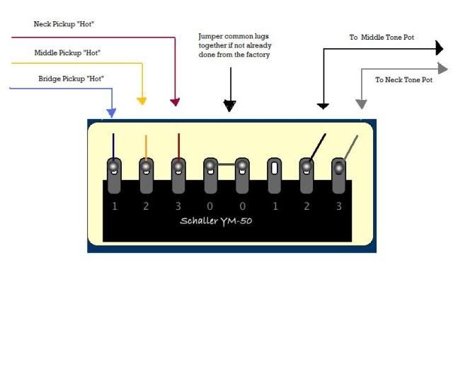 |
|
|
|
Post by cynical1 on Apr 15, 2011 21:53:47 GMT -5
Well, I love a good Google search challenge... I discovered that the RG140 is the same guitar as the RG340, except for the trem-leo...the 140 is a knife edge and the 340 had a Floydish Rose. I gleaned this from a legacy 1988 Ibanez catalog page I found.   That said, and the fact both are H-S-S "duo-tone" (whatever that means...) models, this should get you pretty close:  Hope this helps. Happy Trails Cynical One |
|
bladexx
Rookie Solder Flinger
Posts: 11
Likes: 0
|
Post by bladexx on Apr 16, 2011 12:46:47 GMT -5
ok.. my macro cam is mia, i got pic with the wifes cam, but still gotta transfer, resize, then upload 2 a server and link + draw the diagram and upload, just been 2 busy, but...
newey thx 4 the sw diag...mine only has one tone but that gives me some options on unused lugs esp when I get ready 2 do a good mod, and now I got reassurance on the config
sbg ur right about the HB...I removed the tape from it and I can rewire it for a 4 wire lead...the way it is wired now is for coil tap...stranded 2 HB frame, red from adj coil to frame 4 ground, black from adj coil to black from fixed coil, red from fixed coil to red lead, white from lead to the blacks, so when white is connected to p-p sw it bypasses one of the coils on the HB...what I thought was interesting is grounding white does the bypass like it's supposed to, but if I connect it to the red lead, both coils are hot and alot louder...doesnt seem like it should work that way to me, but even though I can wire a guitar correctly, I am still surprised the whole circuit doesnt ground out and do nothing..
cynical thx 4 the diag, this rig is almost like that... I am close to the orig setup all it took was a test lead while the circuit was hot...
mine differs, my vol is the plain pot, the tone is the p-p, the capacitor goes from the 1st lug on the tone pot, through the center lugs on the p-p switch, then to ground. So I can use the top or bottom lug on the switch for the white tap wire and either have straight strat single coil setup with the sw down and pull it 4 hb active, or the reverse, hb active unless I pull it...so 4 now I will not rewire the hb lead... also, there were no wires from the other end of the selector sw to tone... sbg's diag if i remember right didnt have that either, so maybe that was right. I will test and when I am finished we will have a correct factory setup diagram, and there are a lot of people looking 4 one on the net. after that, I want to explore the possibilities of modified setups with the factory parts before I decide on the right mod 4 me or adding new switches, etc...even though I may add a sw or something if I decide 2 4 wire the HB...it would be nice to have a neck and bridge on option, 2 single and single(neck)-hb...but that i think would require a diff sw or an extra..more later, time to solder
|
|
bladexx
Rookie Solder Flinger
Posts: 11
Likes: 0
|
Post by bladexx on Apr 16, 2011 13:14:22 GMT -5
I forgot, on the above sw diag newey posted, the left side pup 2 sw setup is how mine looks, the center lugs are soldered, but there is also a wire soldered from those lugs to the left vol lug , and a wire from the left vol lug to center tone lug,so...
3-red hb lead, 2-mid, 1-neck, 0-0 together with wire to left vol lug, left vol lug to center tone lug, then 1, 2, 3 empty.
center vol lug to input jack, right tone lug to cap, cap through center p-p, then to ground, white coil tap lead to top left p-p lug.
as far as I can tell, this will give me the setup in the pic from cynical, with coil cancelling when I pull the tone knob, but I dont know yet if the tone pot will control tone, I might need to remove the wire from the vol lug that goes to the center tone lug and solder it to the empty 2 and 3 lugs on the switch? when i plugged it up BEFORE I took it apart, both pots were vol and the singles werent even connected...the originals were broken and taped in place, so someone tried to replace them and couldnt figure out the wiring...new switch and all I got $55 and 3 hours in it so far, and a headache from the squirrels nest of wire I had to untangle, lol
|
|
|
|
Post by newey on Apr 16, 2011 15:35:58 GMT -5
Sorry I left that out. Yes, that is your output to the volume pot, off either of the center lugs.
|
|
bladexx
Rookie Solder Flinger
Posts: 11
Likes: 0
|
Post by bladexx on Apr 21, 2011 14:57:43 GMT -5
managed 2 get everything hooked up...single pups are great...they are supposed 2 be matched to the hb pup, all three have a magnet on the back...singles are loud, but hb has half the output...seems if I connect the coil tap wire to hot I get more output, but then no single option...will post pics and diagram soon I hope
|
|
bladexx
Rookie Solder Flinger
Posts: 11
Likes: 0
|
Post by bladexx on Apr 25, 2011 11:04:11 GMT -5
for some reason photobucket refuses to let me register. Any other recommended sites 4 pics?
|
|
|
|
Post by newey on Apr 25, 2011 11:40:00 GMT -5
Imageshack is the other one folks use here. I don't know why Photobucket is giving you problems; were you perhaps already registered with them under the same name?
|
|
bladexx
Rookie Solder Flinger
Posts: 11
Likes: 0
|
Post by bladexx on Apr 26, 2011 8:11:01 GMT -5
I dont know either..I thought of that, I tried the password recovery in case I had used it in the past, and my email was not found...I will try again and will try imageshack, thanks
|
|
bladexx
Rookie Solder Flinger
Posts: 11
Likes: 0
|
Post by bladexx on Apr 26, 2011 8:55:43 GMT -5
|
|
bladexx
Rookie Solder Flinger
Posts: 11
Likes: 0
|
Post by bladexx on Apr 26, 2011 9:11:23 GMT -5
k...the colors I used in mspaint arent showing up right, but this is how the wiring was set up...the three lugs on the left side of the switch are empty...I was thinking of removing the tone wire from the vol lug and moving it to 1 and 2 lugs which will connect it to my single and bypass my hb, except for when I set the switch to hb and mid pups...
If I cant get the buzz down when I am not touching the strings, and if I cant get more output from my hb then I am ready to mod...sounded like everything was good when I tested with jumpers and a paperclip before I soldered...vol and tone controls are good, no scratch when the knobs are rotated, and good response...new input plug while I was in there...
|
|
|
|
Post by ashcatlt on Apr 26, 2011 10:37:18 GMT -5
Is the HB wired like this from the factory or did somebody mess with it?
You said the "full HB" is less output than when the split wire is connected to hot output? How's the noise in each situation? Is the "full HB" noticeably noisier - compensated for the overall volume difference?
Do you have a meter?
|
|
bladexx
Rookie Solder Flinger
Posts: 11
Likes: 0
|
Post by bladexx on Apr 27, 2011 8:49:56 GMT -5
cynical, I am trying to understand the push pull part of the diagram u found...
it seems to me that on my switch the center lugs are common, and push position activates bottom lugs, pulling activates the top...so in my diagram pulling the switch grounds the coil tap bypassing a coil...in yours the hot (blue) comes from the switch to the HB, white leaves the HB and goes to the pull side of the switch...if I hooked my switch up that way, pulling it would give me hb mode if I grounded out the other side of the black lug, but pushing it would cause me to lose signal since it would connect red and black to ground but not to white.
The only way I could see a true duo working is if that switch is different internally and pulling grounds white, pushing grounds black and loops red and white...the diagram is detailed enough that the switch looks to have an extra block on the side...maybe I am over thinking it this is my first p/p switch
I will have to ohm it but I am pretty sure my six lug p/p has the 2 centers common and just connects of the outer 2 depending upon switch position, so I dont think I can wire my switch that way..I was gonna try it and rewire my HB and p/p using your diagram to see if that helped me out, I know rewiring the hb would give me more options, but as long as I can go hb or single having 4 wires is not important right now
If I can get it to work like it is and get the buzz out of it the I was thinking of getting a diff pup selector switch so maybe I could mod it to have neck, neck-mid, mid, mid-hb, hb, neck-hb...and the p/p allowing for single coil instead of hb...plus if I change the sw I might have enough room to insulate the control cavity. I was going to insulate it to see if that would help the buzz but there isnt enough room. as long as I am touching metal somewhere it is quiet..
|
|
bladexx
Rookie Solder Flinger
Posts: 11
Likes: 0
|
Post by bladexx on Apr 27, 2011 9:02:40 GMT -5
ash, yep, got a meter...it was wired from the factory this way...all of it wasnt hooked up when i got it, the singles are new, but the config is the same, I put everything back like it was 98% positive, I went so far as to break out the magnifying glass to inspect lugs...the goofy thing is if I connect the coil tap wire which is supposed to go to ground to hot where my red wire is on the 5-way then it has as much output as the singles, at least as far as I can tell with a paperclip...it seems to me white to hot should just bypass the other side of the coil..that could be what it is doing and the one coil is so strong that it is picking up when I tap on the opposite one...hooking it up the way it is supposed to go I get less than half the output no matter if the tap is activated or not...I will try to test it more tonight..
|
|
|
|
Post by ashcatlt on Apr 28, 2011 8:58:19 GMT -5
Measure DC resistance between the pairs on the HB - like from + to - and from + (and -) to the tap wire. This is preferably done out of circuit.
|
|