mortis1369
Rookie Solder Flinger

Posts: 22
Likes: 0
|
Post by mortis1369 on Jun 11, 2011 1:36:03 GMT -5
Hello, I recently acquired a 1979 stratocaster that was in REALLY rough shape. In an attempt to make it better, I bought a whole load of new parts. When I first plugged it in, I got this annoying humming at all time of the day. So, when I took it apart, what I found was: 250K pots, a 5 way switch that looked really bad, and the pickups appeared to have "copper decay" buildup on it. I bought 500k pots, a new 5 way switch, 2 humbucker pickups, as well as the pickguard to go with it. I installed all of it, mirroring the wiring as best as I could (it was a little difficult considering I was making the jump from 3 pickups to 2), then I plugged it in, and got nothing. There is a low hum when I touch the strings still, but other than that no noise whatsoever. Sad Day...  . I began looking online for the solution to my problem, but have found nothing that has been dumbed down enough for someone with very little wiring experience to understand. I have come here out of sheer desperation in the hopes that someone here can help me out. Please note, that other than the loss of the middle pickup, the wiring has been completely mirrored. I am just trying to figure out what I did wrong. I can provide pictures if necessary. Thanks in advance. mortis |
|
|
|
Post by newey on Jun 11, 2011 7:56:40 GMT -5
mortis:
Hello and Welcome to GNutz2!
Troubleshooting over the net is difficult but we'll try to help. Well-focused pictures can help, but better yet is for you to draw up a diagram of your rewiring and post it. That way, we can check your scheme for errors.
More advanced troubleshooting will require a multimeter. In general, with no output whatsoever, my suspicion is a bad connection somewhere between the 5-way switch and the jack. Start at the output jack, and work your way backwards to the pots, double checking every connection.
You can also hit all your solder connections with the iron again, briefly- if there was a bad one, doing so will often fix things.
You troubleshoot this with the strings off and the pickguard hanging loose- a screwdriver tap on each pickup will tell you if you've got output without the need for destringing/restringing.
|
|
|
|
Post by sbgodofmetal on Jun 11, 2011 10:32:33 GMT -5
Also unless your using 4 conductor wire humbuckers, and doing some coil selecting or other fancy mods, you only really need a 3 way blade switch. lt will look, feel, and wire in just the same as the 5 way, you just wont have pos, 2&4 any more.
|
|
|
|
Post by sbgodofmetal on Jun 11, 2011 10:38:27 GMT -5
You can also check out www.1728.org its owned and operated by our own Wolf. lts got standard wiring and a boat load of mods too. and check out the band name generator for a few good laughs as well. |
|
|
|
Post by sumgai on Jun 11, 2011 17:39:12 GMT -5
sbGawdom, Boy, you aren't missing a trick, are you? ;D I see a +1 is in your future.  ~!~!~!~!~!~ mortis, Hi, and  to the NutzHouse! Sorry, but this triggered my Nutzness, full on: I began looking online .... but have found nothing that has been dumbed down enough I can just see it now, a new banner to accompany our logo, above: GuitarNutz2: Dumbing down the Internet for guitar dweebs since 1996! I dreamed up a few others, but they'd just be over the top. Sooooo...... moving right along, on to your question. The previous posters essentially have it correct, however, there are two ways to test your components and your circuit. One of them depends only on the components themselves, but it's time intensive. The other method requires a multimeter, something that should be in everyone's toolbox, but sometimes it's not. So the question to you is, do you have a multimeter? (Sometimes abbreviated as DMM - digital multi-meter.) It can be an old analog one, for our purposes that will also work OK. Awaiting your answer, sumgai |
|
mortis1369
Rookie Solder Flinger
Posts: 22
Likes: 0
|
Post by mortis1369 on Jun 12, 2011 16:45:28 GMT -5
No I no longer have a multimeter. Long story short, ex took my tools when we split up and havent gotten around to buying a new one yet. LOL Unfortunate as it is. Anyways, I will draw up a diagram for you. Also, As for the 5 way to 3 way switch. I am going to bridge the two pickups to position 4 so it grabs a different tone, I will be running this through a toggle switch (because if I don't, it wont matter what position the switch is in it will always be running both of them.) And about dumbing it down, I have never had the opportunity to learn from anyone, so I have learned everything that I know about electronics from doing it. Next post will contain a picture of a wiring diagram.
mortis
|
|
mortis1369
Rookie Solder Flinger
Posts: 22
Likes: 0
|
Post by mortis1369 on Jun 12, 2011 21:31:33 GMT -5
Here is the diagram. If it isnt big enough, I will try to take a pic with my wife's phone. Hope it helps.  Red is a positive wire. Black is ground. Purple is IDK WTH it is. And Blue is the hardware. |
|
|
|
Post by newey on Jun 12, 2011 22:06:07 GMT -5
mortis-
That's fine, except that the connections on your 5-way switch are not diagrammed in a manner which we can comprehend, at least not easily. A std. Strat 5-way switch has 8 terminals, four per side. Your diagram looks like it has 7 per side, for a total of 14. So, I can't make out your switching. A photo of the switch would help.
A multimeter would be hugely helpful. You've spent a bit of coin on this thing already, so pony up another $15-$20 and get a cheap multimeter.
|
|
|
|
Post by newey on Jun 12, 2011 22:22:55 GMT -5
Your 5-way switch probably looks like one of these 2 types. Which one? (Images courtesy of ChrisK's templates sheet . . .) In fact, you can use one or the other of these to redraw your switch- just cut and paste.  |
|
mortis1369
Rookie Solder Flinger
Posts: 22
Likes: 0
|
Post by mortis1369 on Jun 12, 2011 22:39:36 GMT -5
it is the 5 way import switch. It only has 7 terminals. So that is where I am assuming I am making my mistake. But I didnt figure that a switch would make that big of a difference, as it just changes between sounds basically. When I moved the switch to different positions, it changed nothing. I will use photoshop to modify this to a more easily comprehensible manner.
|
|
mortis1369
Rookie Solder Flinger
Posts: 22
Likes: 0
|
Post by mortis1369 on Jun 12, 2011 22:50:27 GMT -5
... I lied... I feel a little moronic right now. I didnt see the post on the actual mechanism. I am recreating my wiring diagram.
|
|
mortis1369
Rookie Solder Flinger
Posts: 22
Likes: 0
|
Post by mortis1369 on Jun 12, 2011 23:05:14 GMT -5
 This one might be better, but I would like to thank all of you for your patience with an uber noob like myself, lol |
|
mortis1369
Rookie Solder Flinger
Posts: 22
Likes: 0
|
Post by mortis1369 on Jun 12, 2011 23:32:13 GMT -5
so if I switch them over, now that I have noticed the extra post, will that do the trick?
|
|
|
|
Post by newey on Jun 12, 2011 23:37:39 GMT -5
Mortis- I think your switch wiring has some issues, but I'm not sure those issues would result in no output in any position. Bedtime now, but I'll draw up a diagram for HH wiring with a 5-way if you give me a day or two. |
|
mortis1369
Rookie Solder Flinger
Posts: 22
Likes: 0
|
Post by mortis1369 on Jun 13, 2011 1:23:40 GMT -5
That would be great mate! I just want to get my guitar up an running!
|
|
|
|
Post by newey on Jun 13, 2011 22:23:37 GMT -5
Mortis- I'm not sure what you were aiming for with the switching. Here's 2 possible schemes (your choice as to which redundant positions you want). Another possibility would be an "off" position at one end of the 5-way. Otherwise, with a 5-way switch, but with only 2-wire humbuckers (I assume that's what you have based upon the drawing), there are real limits on your options. Anyway, let me know if either of these is what you're after: 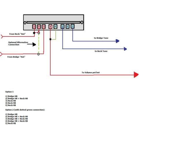 (sorry for the small image size) |
|
|
|
Post by ashcatlt on Jun 14, 2011 0:23:17 GMT -5
With only 7 lugs on the switch, it leaves you with more limited options. It also likely leaves you wondering which of the lugs in newey's diagram to omit.
We've actually seen a couple of different 7 lug five-ways around here. Most often, I think, the two common lugs (marked "P" in newey's diagram) are joined together internally. The only way to be sure how yours works is to test it, but if it's like that then you can just leave out that jumper between the P's, count them both as one lug, and wire the rest of the switch as shown.
If that doesn't work... We'll cross that bridge when we have to.
|
|
|
|
Post by newey on Jun 14, 2011 5:26:18 GMT -5
Mortis said:
But then we had:
And later posted a revised diagram using the 8-lug template.
Which I took to mean there were actually eight lugs. If it's actually one of the 7-luggers, then Ash is right.
We've seen 2 types of the 7-luggers; one type has the common lug along the bottom, in line with the other lugs, while the second type has it in the middle of the side of the switch, at the point of rotation of the lever. Again, if there's any question, a photo would resolve it.
|
|
mortis1369
Rookie Solder Flinger
Posts: 22
Likes: 0
|
Post by mortis1369 on Jun 14, 2011 16:57:18 GMT -5
Lol this explain it? It was just kinda THERE. So yes, I have 8 terminals. I am Attempting to rewire it right now using the template provided here. Will let you all know how it goes.  |
|
|
|
Post by ashcatlt on Jun 14, 2011 17:17:29 GMT -5
That one you missed is probably frame ground. Not connected to the switch itself at all. There's only 7 lugs if interest. The one dead center is both of the lugs marked P in newey's diagram at the same time.
|
|
|
|
Post by thetragichero on Jun 14, 2011 17:29:41 GMT -5
time to get out the meter and check!
i do this with all my switches (probably a little OCD, but whatever...)
|
|
|
|
Post by sbgodofmetal on Jun 16, 2011 0:45:49 GMT -5
looking at neweys diagram either way you go, your going to have around 3 pos, exactly the same so as to not have a studdering switch here's a few ideas, 1, Add 2 (lvd) schottky diodes in parallel for a subtle passive overdrive, 2, and different valued caps directly to the pup lugs for darker tones in the higher pos'. 3, just use a 3way blade and add some push/pull pots to add series/parallel, p/Oop, solo ect... diagrams for these can all be found at www.1728.org |
|
mortis1369
Rookie Solder Flinger
Posts: 22
Likes: 0
|
Post by mortis1369 on Jun 17, 2011 1:01:05 GMT -5
Well, I am thinking about putting a diode on position 2, bridging it to pos 1. And then bridging over both pickups through another diode into pos 4. But for an update, I still got nothing. I think on payday I am just going to have to go and pick up a multimeter...
|
|
mortis1369
Rookie Solder Flinger
Posts: 22
Likes: 0
|
Post by mortis1369 on Jun 17, 2011 1:07:52 GMT -5
Also, I am unsure as to whether or not my old switch had issues, I could possibly try going back to that old one to see if that does the trick. I only replaced it because I was replacing everything else, and I found a good deal on all the pots and the switch together.
|
|
|
|
Post by newey on Jun 17, 2011 5:10:23 GMT -5
If these are not new items, then you definitely need to get a meter and check to see that the components are OK. Otherwise you can spend inordinate time tracing down a wiring issue that may not exist . . .
|
|
mortis1369
Rookie Solder Flinger
Posts: 22
Likes: 0
|
Post by mortis1369 on Jun 17, 2011 5:34:25 GMT -5
no, they were all new. Taken directly from a new strat with the exception of the switch which was obviously not from a strat as it only has 7 posts... lol but I think that I will try it out with my old switch and see if it works. I have tomorrow off of work so I will have time to troubleshoot.
|
|
mortis1369
Rookie Solder Flinger
Posts: 22
Likes: 0
|
Post by mortis1369 on Jun 17, 2011 23:58:48 GMT -5
I switched back to my old 5 way, and it works for the most part. I wired it exactly as newey's diagram suggests, and only 2 of 5 positions work. I am assuming that I was right to buy a new switch, its just unfortunate that it didnt work. Oh well, Thank you all. I think I will remain a member here, and try to learn as well as help.
|
|
|
|
Post by newey on Jun 18, 2011 8:26:44 GMT -5
We can help you fix this. Which 2 positions work?
Wiring fails a lot more often than switches.. But I suggested checking all components first, it only takes a few minutes, and it's time well spent down the road, if troubleshooting needs to be done. Of course, one needs a multimeter to do so.
The 7-lug switch is a type commonly used on "Strats"- just not on the ones that Fender makes (unless Squier is using those nowadays). The ones I have seen have been of Asian origin and used on guitars from there.
The original Tele/Strat lever switches were 3-way, and were used in intercoms, radios and so forth (for "On/Off/Standby", usually). Since tubes take a while to heat up, a standby setting was useful.
Leo apparently got a big surplus of these, probably excess WWII production, and just kept using them. For Strat use, the 2 commons aren't really needed, since they are ordinarily wired together.
Eventually, some bean counter figured out that it would be cheaper to eliminate a lug and just tie both poles into the same common.
|
|
mortis1369
Rookie Solder Flinger
Posts: 22
Likes: 0
|
Post by mortis1369 on Jun 19, 2011 16:27:15 GMT -5
Well the two that work are on the bottom of the switch (pos 4 and 5 I believe they are classified as). One uses the bridge pickup, and the other uses both. But when I plugged it in, it still gives me the humming which was the reason why i bought all this new stuff. Perhaps it was the switch, considering that the switch is now the only original piece that I have. lol, I think I will buy a genuine fender switch and use that instead of re using the old one, or trying this random 7 post POS.
|
|
|
|
Post by newey on Jun 19, 2011 19:48:49 GMT -5
With 2 HBs, hum should be a thing of the past. So something is definitely amiss here, and as you say, you've replaced everything else but the switch . . .
The only other suggestion I have is to basically re-ground everything. Remember that elusive "8th contact"? Try running a frame ground for the switch to the back of one of the pots, assuming that's where your grounds are collected now. And hit all those existing ones with your iron.
Then, the inoperable neck pickup is a separate problem.
|
|


 . I began looking online for the solution to my problem, but have found nothing that has been dumbed down enough for someone with very little wiring experience to understand. I have come here out of sheer desperation in the hopes that someone here can help me out. Please note, that other than the loss of the middle pickup, the wiring has been completely mirrored. I am just trying to figure out what I did wrong. I can provide pictures if necessary.


