railer80
Rookie Solder Flinger

Posts: 8
Likes: 0
|
Post by railer80 on Aug 13, 2011 19:17:16 GMT -5
Okay, so i decided to buy a megaswitch from stewmac for installing these new pups...im having trouble grasping the concept og the number assignments and what i need to connect, ive read the instructions on stewmacs site, its just not clicking. I bought the t model for a tele, because i only need 3 way. Here is a quick schematic of what i have planned out so far, just no sure how to throw the switch into the circuit...  |
|
|
|
Post by newey on Aug 13, 2011 20:13:43 GMT -5
railer80- Hello and Welcome to G-Nutz2! It's a little difficult to read all the connections on your diagram, but there are problems. Don't despair, first-time posters who submit a diagram with a question get extra brownie points here, even if it's a "work in progress".  The center connection on your volume pots isn't connected. The center lug on a pot has to be connected to something in order for the pot to work. The center lug is the "wiper", the moving part connected to the shaft and knob that varies the resistance as the shaft is rotated. Connecting only to the outside lugs results in a fixed resistance regardless of turning the knob. The output jack "hot" line is also unconnected to anything. But, let's forget about the V and T pots for the moment, since the switch needs to go in the middle of this anyway. We'll work on integrating the switch, then worry about wiring further down the signal chain. First, we need to know the switch logic of your switch, the Schaller Megaswitch Model "T". |
|
|
|
Post by newey on Aug 13, 2011 20:26:10 GMT -5
Here's the switch logic: 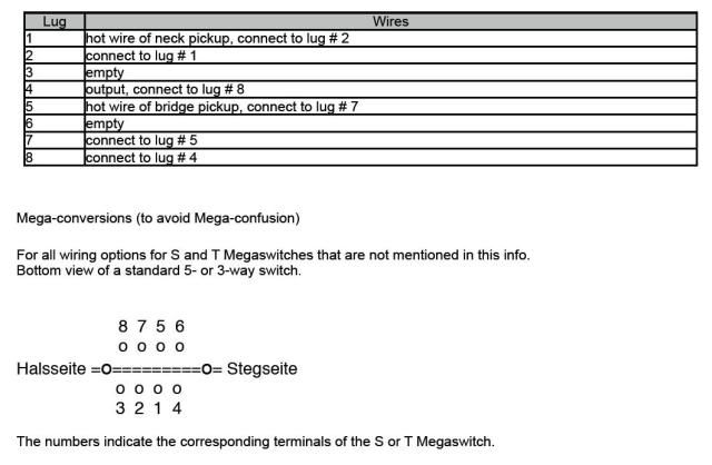 Now, let's zero in on what difficulties you are having. |
|
railer80
Rookie Solder Flinger
Posts: 8
Likes: 0
|
Post by railer80 on Aug 13, 2011 20:33:45 GMT -5
Hey, and thanks for the warm welcome! Well i was going to the wire from the center lug through the switch? At least that's how Seymour Duncan appears to have it on their diagram? Alright, the switch is my biggest problem right now...here is the most info ive found on the theory behind it: www.stewmac.com/shop/Electronics,_pickups/Components:_Switches_and_knobs/Megaswitches/Megaswitch_E-Model.html?tab=Instructions#details This is actually the model i have: www.stewmac.com/shop/Electronics,_pickups/Components:_Switches_and_knobs/Megaswitches/Megaswitch_T-Model.html I just need the switch to do the standard "bridge/neck+bridge/neck". Thanks again though, im somewhat new to doing guitar wiring, so i appreciate you guys not tearing me into pieces. lol |
|
railer80
Rookie Solder Flinger
Posts: 8
Likes: 0
|
Post by railer80 on Aug 13, 2011 20:36:07 GMT -5
Okay, its the numbered lugs, im not understanding the idea behind them and how they tie into everything, if i saw it in a diagram form i probably would. But maybe i need to go back to the basics and understand all of the terminology?
Just trying to finish this guitar up. lol.
|
|
|
|
Post by newey on Aug 13, 2011 21:42:00 GMT -5
Ah, OK. If you are having individual volume controls, they go before the switch; the tone control will go after the switch. With a master tone control, though, you will have some interaction. If you haven't bought components yet, a dual-gang pot (not a concentric pot, but two pots on a single shaft) takes care of that issue, it allows you to wire the V and T just like on an LP, just that both tones are on a single knob.
But some folks don't care much that interaction, it will certainly work that way, it's up to you to decide.
Your link is to the Megaswitch Model "E" which is a different switch. Ignore that. For the "T" model, see the info I posted above.
Well, according to the picture, it looks like the lugs are actually lettered instead of numbered, but it's hard to see in the photos. Does yours have letters or numbers?
|
|
|
|
Post by newey on Aug 13, 2011 21:55:48 GMT -5
Does this help? 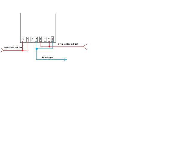 |
|
railer80
Rookie Solder Flinger
Posts: 8
Likes: 0
|
Post by railer80 on Aug 13, 2011 22:24:15 GMT -5
Ah, OK. If you are having individual volume controls, they go before the switch; the tone control will go after the switch. With a master tone control, though, you will have some interaction. If you haven't bought components yet, a dual-gang pot (not a concentric pot, but two pots on a single shaft) takes care of that issue, it allows you to wire the V and T just like on an LP, just that both tones are on a single knob. But some folks don't care much that interaction, it will certainly work that way, it's up to you to decide. Your link is to the Megaswitch Model "E" which is a different switch. Ignore that. For the "T" model, see the info I posted above. Well, according to the picture, it looks like the lugs are actually lettered instead of numbered, but it's hard to see in the photos. Does yours have letters or numbers? I done care much for the interaction, as this guitar will not be very versatile, tone wise. Mainly a metal guitar, i have others for everything else. Mine are numbered 1-8. Im kindof starting to understand this thing? WHich wire would be the hotwire, cant seem to find any of that... |
|
|
|
Post by newey on Aug 13, 2011 23:00:24 GMT -5
Just follow the numbers above, then.
All of the wires to the switch are "hot" (in quotes because it's a somewhat-misleading shorthand.).
We're not showing any grounds here, they would go according to the Tele diagram linked to earlier.
All of the switching is done on the "hot" side of the circuit in this scheme. The switch connects the bridge "Hot", which will be coming off your volume pot center lug, and the neck "hot", likewise from the other pot. The output of the switch is at Lug #4, that's one of the "Common" or "Pole" lugs, #4 is in turn connected via a jumper wire to #8, which is the other Pole.
#4, the output, then connects to the tone pot "Hot" and then out to the hot end of the jack.
The grounds are all collected in one place, or linked together in some fashion, and then connected to the Output Jack "Not Hot" lug.
Please redraw your diagram with this information, and if it's got any errors, we'll correct them before you begin wiring it.
|
|
railer80
Rookie Solder Flinger
Posts: 8
Likes: 0
|
Post by railer80 on Aug 13, 2011 23:10:42 GMT -5
Does this help? Okay this does, these would go to the center lugs on the pots, correct? EDIT: disregard last, im kinda slow haha. |
|
railer80
Rookie Solder Flinger
Posts: 8
Likes: 0
|
Post by railer80 on Aug 14, 2011 0:08:19 GMT -5
New and improved(hopefully). Made it a little neater for you guys.  |
|
|
|
Post by newey on Aug 14, 2011 9:06:25 GMT -5
Railer- You're getting close, it all looks good up to the tone control. Move the output wire from the center lug of the tone pot to the upper lug ("upper" as shown on your diagram). Leave the capacitor "as is". The upper lug then connects to the output jack as shown. Now, your drawing of the output jack makes it difficult to tell which connection is which, but it appears that you have the tip (center) lug connected to ground. If so, the connections need to be reversed. The wire from the upper tone control lug goes to the tip, the sleeve is grounded. Now, having said all that, let's also await someone else weighing in to be sure this is OK. Two heads are better . . . .  |
|
railer80
Rookie Solder Flinger
Posts: 8
Likes: 0
|
Post by railer80 on Aug 14, 2011 15:56:22 GMT -5
Alright, here is my interpretation on what you told me to do. hopefully this ones a keeper. Im actually, starting to understand this stuff?  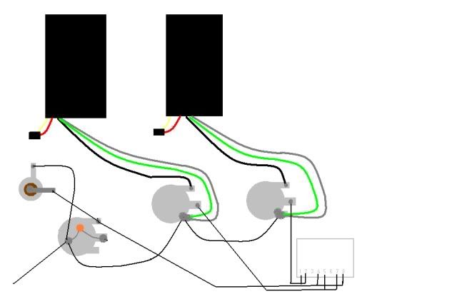 |
|
|
|
Post by newey on Aug 14, 2011 17:23:41 GMT -5
That's exactly what I meant. Now, if someone will be good enough to verify this, then you should be good to go.
|
|
railer80
Rookie Solder Flinger
Posts: 8
Likes: 0
|
Post by railer80 on Aug 14, 2011 17:39:25 GMT -5
That's exactly what I meant. Now, if someone will be good enough to verify this, then you should be good to go. awesome...ill have future projects lined up so all this help is greatly appreciated. i plan on stayin active on here, seems theres a lot to learn! |
|


