bdawson7
Rookie Solder Flinger

Posts: 16
Likes: 0
|
Post by bdawson7 on Oct 29, 2011 23:06:37 GMT -5
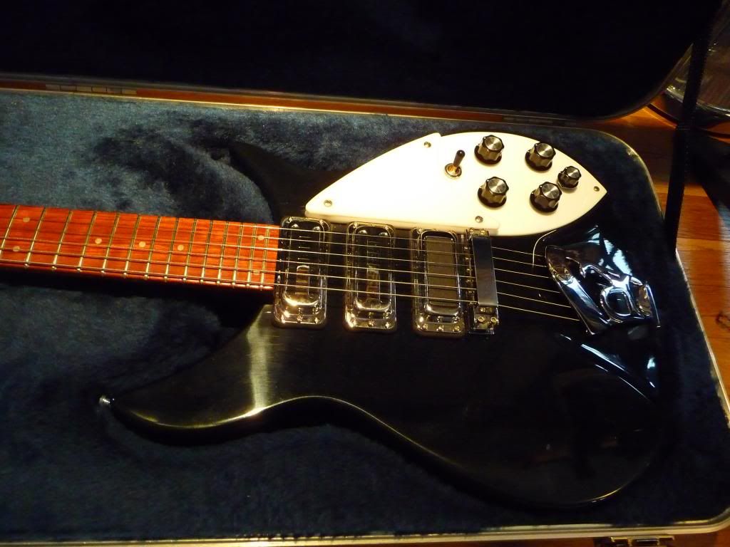
Hi all, long time lurker, first-time poster. I finally acquired my first Rick, a perfect black 350 Liverpool from 1995 with hi-gains that I hope to turn into a 350SH look-a-like someday, with all that pretty binding. But first I will install 2 toasters and 1 HB and alter the wiring. I've been playing a Les Paul forever that I just modified to Jimmy Page wiring with 4 push/pulls; I also have a Brian May, and I love the versatility of his switching system, I think everyone is familiar with the general drivetrain in these machines. I want to fit all of this into the 350, and keep the original look and feel, by swapping all the pots for push/pulls, and using 2 toasters and 1 HB like on the 350SH. I would of course keep the original wiring harness separate, just in case. My idea is below. It basically combines a common RIC mod of 5th knob for middle p/u volume, Neck/N+B/Bridge toggle switch (it comes as N+M, N+M+B, B), Brian May phase switching for each p/u, Jimmy Page coil tap on the HB and series/parallel switching between 2 p/ups. I'm wondering about some of the details I have not experienced in my previous messing around with Gibsons and strats... 1. Should I use a 500k pot for the HB and RIC 330k pots for the toaster volumes? Use RICs 330k for tone or 250k? Or all the same? 2. I think the most versatile combo to switch series/parallel is with the neck and middle p/ups. What do you think? 3. I was also thinking about using the "Free-Way" 6-position Les Paul switch at Stew-Mac to allow more flexible p/u selection, but its getting bad reviews. and its not black. 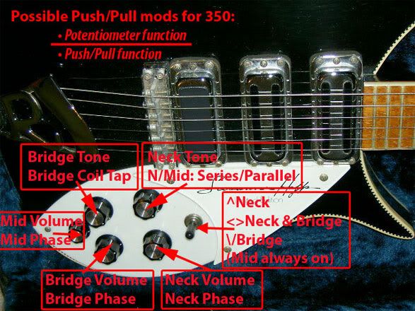 4. My biggest need for help is with the series/parallel switch, and being able to keep each individual pickup phase switchable, and keep the Middle on independent volume control. So that when in series, I can blend the Mid into the Neck, and the neck can be the master volume of the two, similar to how the JPLP is wired. Also when in Parallel the Mid will still be always on with the separate volume control. My schematics are maybe more, well, impressionistic than many I've seen here, and have evolved over a few days. I will remove the shield wire from the case of the two toasters and run new grounds because they are wired like tele p/ups, and I used blue and red just for continuity sake. The series/parallel section is near the top, not quite sure how this should look..... first try: (Does that green wire go there?)  second try: (Doesn't work when neck vol p/p up, neck tone p/p up? = series/oop) 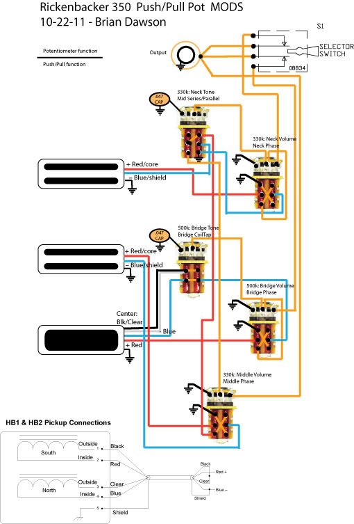 latest try: (Doesn't work when neck vol p/p up, neck tone p/p up? = series/oop)  What is the right way to get that series up/parallel down push/pull goin? Thanks a ton... |
|
|
|
Post by JohnH on Oct 30, 2011 1:59:48 GMT -5
Hi bdawson7 - welcome to GN2! You are obviously a complete GNut, and you have a nice project going on there. I'm sure there will be lots of thoughts and ideas forthcoming (I have a few in mind), but to begin with, I just wanted open the door and welcome you inside.
cheers
John
|
|
|
|
Post by newey on Oct 30, 2011 8:47:37 GMT -5
bdawson- Hello and Welcome to G-Nutz2! Now, we often get folks who come in here and ask questions along the lines of: "I have such and such pile of parts, what can I do with them?" We try to be helpful, but vague queries are tough. You, on the other hand, show up with a completed diagram straight out of the box. And it's a darned good diagram, I wouldn't call it impressionistic. It looks better than most of my efforts. All of this is by way of saying you earn a +1 right out of the box, and that's something that doesn't happen very often!  Now, on to your specific problem which you have identified correctly. The series/parallel push/pull isn't playing nicely with your neck phase switch. Depending on the position of the mid phase switch, the series setting may end up with both ends of the chain grounded, which leads to no output. The solution lies in moving the position of the neck phase switch in the scheme of things. Move the neck phase switch so that it is "first in line" after the neck pickup, and move the neck volume pot wiring there as well. Then the series/parallel switch interposes itself between both phase switches and the output or the selector switch, (depending on the parallel/series setting). Do that, and I think your problem will become easily solvable.  Now, at this juncture I must point out (as I do to all fans of the Brian May switching) that having 3 phase switches for 3 pickups is redundant. 2 phase switches will produce all possible OOP settings for 3 pickups, and it doesn't matter which 2 of the 3 get the phase switches. While redundancy in switching is certainly no sin, and to each their own, etc., in your case it is complicating matters quite a bit since this guitar moves well beyond the B May switching. (You will have noted that there is a fourth possible OOP setting, that being to put the 2 coils of the HB OOP with each other, but that will produce a very low output signal and is not generally recommended, at least not by me. So I haven't addressed that possibility). IOW, you could lose either the mid or neck phase switch and make your life a lot easier, without losing a single possible sound from the scheme. Or, you could then use the empty P/P pot you get by so doing for something else. Perhaps the mid phase switch becomes a "Mid Off" switch, thereby giving you the N + B sounds you now lack? (I recognize that you can get N + B in your scheme by turning the mid volume down, but a switch is quicker). As far as the other questions you asked: This is largely a matter of taste, and all these choices are compromises anyway, but I think the 500K on the bridge is a good choice. It will brighten up the HB a bit which is usually what most folks want in their bridge pickup, a brighter sound. And you can always turn the bridge tone down a bit to compensate if it's too bright for your tastes. Again, "most versatile" depends on what a person likes. Since you have a bridge HB, by putting the neck and mid in series, you essentially create a "widely-spaced HB" out of those two coils. Put that in parallel with the bridge HB, and you'll have a quasi-LP type of sound. Not a bad choice; others might like to put the bridge in series with the N+M. That might venture more into the B May territory, where 3 single coils are all run in series, although the HB isn't going to sound exactly like a SC even with the coil cut pulled. And putting all 3 pickups in series (the real B May deal) would require more switching, or losing something else. I imagine that the color is just a matter of changing the little plastic "bonnet" on the switch, so that shouldn't be a deal-breaker. We've had some discussion of that switch, and one guy who was proposing to use it, but I don't think we ever heard back from him with a report. So, no word on reliability issues from here. However, it's a fairly sizable piece and you might run into fitment issues with it. You may have fitment issues anyway, so I would advise test-fitting all those P/Ps first, along with the toggle, etc., before you dive into rewiring this. I gather, from your statement about keeping the wiring harness, that modifying the cavity is off the table. (I agree, this is a nice guitar and well on its way to being a classic at age 16). As far as fitment goes, bear in mind that it's not just the components, but the associated wiring as well. Wires are not infinitely bendable/squeezable, and you have to allow some room between things so that connections are not under stress. Again, welcome! Overall, I'd say you're well on your way to an interesting mod of a neat guitar.  |
|
|
|
Post by ashcatlt on Oct 30, 2011 10:54:52 GMT -5
I think newey's got you headed in the right direction, so I pretty much just stopped by to welcome another Rick to the forum. Mine's a 330 with 5 rotary switches. Maybe I'll dig up the link in a bit here.
I also wanted to comment on newey's thing about the phase switches. 3 phase switches is one more than necessary for the out of phase combination sounds. Absolute polarity is generally meaningless, but...
I came across an interesting argument on another forum not long ago. Imagine you're playing a lead part through just one pickup and a relatively loud amp. You hit a note and hold it, and the string goes into that resonate sustain feedback thing. Now you flip the phase switch for whatever pickup you're using. Now the amp, which had been reinforcing the fundamental vibration of the string suddenly starts pushing against it, damping down the fundamental and (at least if you're lucky) causing it to break to a higher harmonic.
I don't remember who they said it was that does this regularly. If you're into that feedback thing, though, this seems like a compelling reason to have the "redundant" third switch.
|
|
bdawson7
Rookie Solder Flinger
Posts: 16
Likes: 0
|
Post by bdawson7 on Oct 30, 2011 12:43:18 GMT -5
Thank you John, Newey, and ashcatit! Fantastic feedback, and info - you are princes of men! Yes, I guess the third (neck) phase switch is one more than necessary. I think the idea in the Red Special is that, at the SPL levels at which Brian May plays, the instrument's resonance is adjustable to a more nuanced degree. He always said he wanted a violin-type sound, and it was designed to feedback, so that extra adjustability is another way to enhance the man-machine interface. I think then if this neck phase switch is complicating things, I can live with getting relative phase switching among the three p/ups with just the neck and middle phase switches, instead of absolute phase for all three. Not planning to play with a wide open AC/30 or Marshall stack! Perhaps the use of the resultant extra Push/pull would be best served as a parallel/series for the bridge, to get the widest possible tone selections. I am definitely interested in getting the big HB sound with N+M. I've seen the other options for making the whole guitar series or parallel, but I want to keep the original look and feel, so push/pulls are all I can use. But I have to figure out the N/M switch first.... Here's what I've got after the suggestion from newey: ( In switch up position are they in true series? I thought signal would have to go from Mid through the Neck pickup itself. ...I also cleaned up the toggle switch.)  I have been basing my parallel/series switch diagram on the following, but I think this diagram has it parallel down/series up: 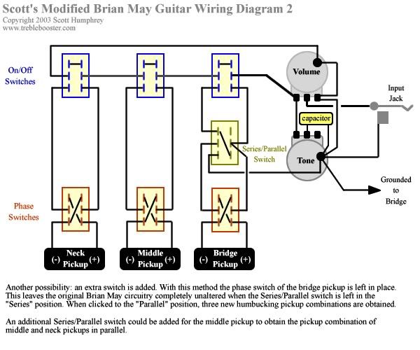 This may be for cause for another post: I will also be adding series down/parallel up push/pulls to my Brian May Guitars (guitar) after hearing some examples of the differences on this board. So I copied the above diagram, and reversed the push/pulls so they are series down/parallel up, but I'm not sure. Are they now series down/parallel up? And will this idea work for the RIC mod? Keep in mind 3 separate volumes. 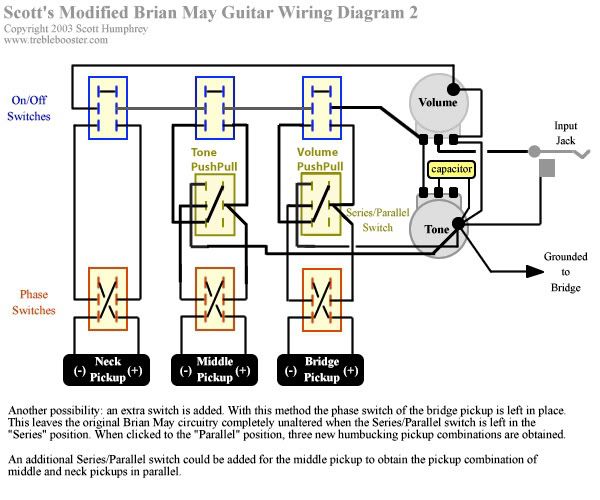 Many thanks again for looking! |
|
bdawson7
Rookie Solder Flinger
Posts: 16
Likes: 0
|
Post by bdawson7 on Oct 30, 2011 13:40:47 GMT -5
Aha, I think I've got the N & M parallel/series solved. But now the Bridge in parallel/series with others.... 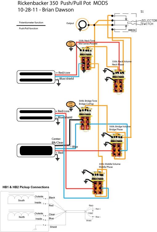 |
|
|
|
Post by newey on Oct 30, 2011 14:57:12 GMT -5
Bdawson-
Your latest looks OK (but let's let someone else weigh in, 2 heads are better, etc.). You threw me off a bit until I realized that the neck phase switch is still there but not wired to anything. But the series/parallel looks good to go now.
Series/parallel for the Bridge works pretty much the same way. But you may have a problem trying to put it in series with both the mid and neck, because your neck/mid series/parallel switch will "break the series chain" and cut the output. To put all 3 in series together requires wiring like the B May scheme which bypasses the unused coils in the series chain.
Another option is using the extra switch for series/parallel between the coils of the bridge HB. I find the parallel HB sound to be very useful.
We had a scheme a while back on adding parallel modes to the series B May scheme, look in the general schematics board (if you didn't already find it).
|
|
|
|
Post by JohnH on Oct 31, 2011 3:24:23 GMT -5
Apologies but I haven’t checked through your nicely drawn diagrams. The work week starts on your Sunday down here and I can’t review them there! But I had a think about what I’d do in your place, based on your pickups together with 5 knobs with switches and a toggle. This is just for interest, not saying it’s any better or anything. I think all the pots would be 500k log, since these are a standard value and would help reduce loading in series combinations. All volume pots would have ‘normal’ wiring, ie output from the centre lug and all would have treble bleed circuits (1nF and 150k in parallel). These volume pots would be wired to the pups before any switches that combine pickups, so that in series modes, they continue to act independently. That way you can set interesting series mixes, and also control the balance of out of phase combinations. I think the B and N tone controls would also be directly across the respective pups. The core of the circuit would be based on an extended LP, switching between B and N, so a volume and tone control dedicated to each as normal, plus three of the switches to do bridge coil-cut, bridge phase reverse and series/parallel between N and B. This then goes to the main toggle, so so far, its similar to a JPLP, without neck coil-cut, but noting the independent volume controls (that’s how I wire my LP designs, see schematics section) That leaves one knob and two switches to control the M pup. The knob is the middle volume, wired directly to the pup as with the other volume pots. One thing I think is quite difficult is to find a way of controlling such a pickup in series and parallel with others, using just a pot (eg a blender or a volume pot). There always seems to be either some unwanted loading or unwanted series resistance which diminishes the tone So I think it is a good idea to be able switch the Middle pickup completely out of circuit. The two switches could be: - both in – middle pup and its volume pot completely out of circuit so no loading or shunting of other pickups
- one out – middle in parallel with whatever else is selected
- other out or both out– middle in series with whatever else
You’d have a simple to operate guitar, which is just like an extended LP in normal use combining B and N, then pull knobs as required to bring in the middle pickup. You would get all possible combinations of the three pickups in series or parallel, including bridge coil cut or reverse phased, and all combinations with full independent mixing of pickups. The price of that however is that there is only one phase switch, though that would be enough IMO. I think you may be heading in a different direction, but I just thought I’d put those thoughts down in case they are useful. cheers John |
|
|
|
Post by asmith on Oct 31, 2011 6:36:27 GMT -5
Bdawson,
Welcome to the NutzHouse. Now that you've actually registered and posted, that's it I'm afraid. Event horizon has been passed. Best of luck.
I've checked over your latest diagram. There are a couple of interesting arrangements; I'm not sure if they're intentional or not.
First, let's quickly dash over that you've wired your volume pots "backwards" as to what one usually finds. I'm sure you already know that - after all, your Mid-volume control's non-interaction with the other pickup outputs depends on it.
Moving on. When you pull the Mid Series / Parallel switch on the Neck Tone pot to put the Neck and Middle in series, it's going to act as a Master volume for both the Neck and the Middle pickups. The Middle Volume is still wired to act as an independent volume for the Middle Pickup. Are you aware of this?
However, your "backwards wiring" on the middle pickup is where this makes it interesting. When you're playing Neck & Middle in Series, and you turn down the Middle Volume, you're not "bypassing" the Middle pickup in the series chain. There's always an additional series resistance of 330k in series with the Neck pickup from the Middle Volume. That's going to dull your Neck output as the Middle Volume is turned down.
I can't see a way to solve this using only DPDTs, while still maintaining the switch logic you have at the moment - i.e. swapping between a Middle Pickup fader in "parallel mode," and the Middle & Neck acting as a humbucker in "series mode."
And so ends the negativity binge. John has some great suggestions in his post. I'm looking forward to your further brainstorms.
A.
|
|
bdawson7
Rookie Solder Flinger
Posts: 16
Likes: 0
|
Post by bdawson7 on Oct 31, 2011 13:32:07 GMT -5
JohnH that is some fantastic ideas. I think then the control layout would look like this for the most logical operation while playing (to me, anyway): 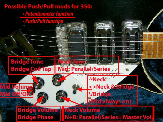 Asmith, yes thanks, I am aware of the backwards wiring, I have used an irongear.co.uk plot as a basis for the beginnings of this project, as I was was familiar with it from working on my (JP)LP, and that diagram works out to have a Master Vol. when in Series, so was aware of that too. If I used standard (not backwards) wiring would the loading of the neck p/u by the mid vol. pot. go away? What is the detriment to keeping the Mid in circuit at all times, instead of taking it out with the on/off(bypass) switch? I kinda want to keep a Mid phase switch to get a funky tone with the big N+M HB. Maybe if I used the FreeWay 6-position controller I could keep the Mid phase switch! |
|
|
|
Post by JohnH on Oct 31, 2011 14:16:27 GMT -5
The problem that asmith refers to is also why I would suggest being able to have the M pup fully disconnected when not used. Forwards wiring is much better on a single pup, and works very well with series wiring, but in a combination, if you turn one pickup down it kills all output. Backwards wiring, as you turn it down, works OK when combined with another pup in parallel, but sounds bad with a single pup or series connection because it adds the pot resistance in series.
To free up a switch, I do my coil cuts using the tone pot. At 10 it is coil cut and at 9 and below its humbucker, using the third pot lug, so no switches needed. Another option would be if you could slip in an on-on-on mini toggle, you could use it for M off, M on in parallel, M on in series, freeing up two switches.
|
|
|
|
Post by JohnH on Oct 31, 2011 14:25:11 GMT -5
Sorry to lower the graphic quality, but here is a sketch I did on the train yesterday (ie its yesterdays ideas):  The pickups, with pots coil cut and phase, form three modules, each with just two wires, so I drew it as a modular diagram. S3 will override S4. John |
|
bdawson7
Rookie Solder Flinger
Posts: 16
Likes: 0
|
Post by bdawson7 on Oct 31, 2011 16:06:24 GMT -5
SICK! That is Astounding, John. Here is a new diagram, as viewed from under the pickguard so its easier to follow in real life when working. I just incorporated these ideas on this latest version. I might add the cap & resistors onto vol. pots in the diagram, easy enough to decide on later. It might need a 500k now at the Mid since that becomes the master volume when all are in series. Regarding the S4, it might not work for my situation, so i just direct connected to the output. I think this could work for all settings. Well, we ended up a little ways away from what I thought i wanted, but I think now there's even more sounds available than I thought of. I was trying to stay as close to RIC parts as possible, and I guess was a little limited in my thinking. However, I feel like not disregarding RIC schemes altogether. Is there any spot I could get away with having 330k pots that are OEM on RICs? Perhaps the tone pots? 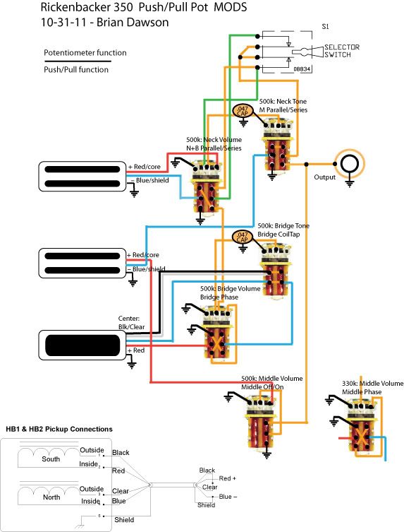 |
|
|
|
Post by newey on Oct 31, 2011 20:00:26 GMT -5
OK, the latest scheme is quite different and I see some issues with it.
First, when the "M Parallel/series" switch is set to series, the only route to the output jack is through the middle pickup. If you then pull the Mid on/off, you will lose all output. Not sure that's what you intended there.
Also, the "N + B Parallel/series" switch seems to have some issues. With it set to series, both ends of the selector switch are connected together, which means the whole selector switch shorts to output. So, if you're set to series on that switch, you'd have to push that back to parallel before you could use the selector to select a single pickup.
Again, let's get another pair of eyes on this, though.
As far as the pots go, if you want 330K pots, use 330K. The difference will be fairly minimal.
Also, standard pots used in guitars are generally only built to a 20% tolerance, meaning a nominal 500K pot could range between 400K and 600K; a nominal 330K pot could be from 263K to 396K. Depending on the 2 pots you pick to compare, there might be as little as 4K difference!
|
|
bdawson7
Rookie Solder Flinger
Posts: 16
Likes: 0
|
Post by bdawson7 on Oct 31, 2011 22:55:18 GMT -5
I guess I can't see another way to get the Mid in series without going through the mid on/off switch. I could get used to that sccenario... Looks to me like thats the way its drawn on Johns schematic.
Yes this part confused me a little on schematic. Looks to me like the top wiper of S1 is set to hit either B+ when down in parallel, or N+ when up in series. When in series mode, the pickup toggle is up (neck) for B+N, and there would be no output at toggle down, because the bridge is routed through the neck. But John put in the connection between S2 up and S1 toggle down to have an output at toggle down, just so theres no dead spot for that switch, as there otherwise would be without that connection. I know that dead spot happens on my JPLP, and is mildly annoying. Perhaps thats what the schematic, as I far as I can tell, might be meaning. I might have drawn that part entirely wrong.
I read that Fryer used Omeg 220K Log B pots for the Red Special replicas in the late 90's, and only one in five fell in the acceptable range of value. I used a multimeter in the local store to find some low values in their 250k batch, tried to find some reasonably lower values pretty quickly, and stopped after i found 2 out of 4 that were pretty low, and even matching, at 232k each.
|
|
|
|
Post by newey on Oct 31, 2011 23:09:26 GMT -5
OK, I didn't realize you were working from JohnH's schematic with your latest effort. I'll have to go back and compare the two, but bed is calling me now.
It's always easier to see these things on a schematic, and then translate to a wiring diagram.
|
|
|
|
Post by JohnH on Nov 1, 2011 2:59:27 GMT -5
I had a look at the diagram above.
I think the way the main toggle is bypassed is OK. The idea is that if you engage a series mode with B and N, you naturally want both pickups acting, and its inconvenient to have to also move the toggle to a certain place to make it work. So this way, you can set the toggle where its wanted for a parallel mode, then leave it there and it is over-ridden when the NB series switch is pulled.
One general difference you have is that all volume and tone pots appear to have a grounded lug.. this will mean that when in series, Each control will affect not only its own pickup but also the others which are on the ground side of it. An all-in-series chain, as drawn here, is ground-B-N-M-output, so the N controls will also affect B and the M volume will also affect B and N. You may want to have master controls, but I think it is more useful, and preserves better tone and better control, to have the controls only acting on their own pickups in series mode, which is how I showed it. I find this useful for adding a small amount of N to a bridge sound, or fully turning down the tone of N keeping the full treble of B etc. Mixing of sound in series works very well like this (if you add the treble bleed parts too!)
The M switches are also a bit different, and as discussed above, there is a potential dead spot if you put M in series mode but don’t also pull the M on switch. Not a problem if you are happy with that, but the way I showed it avoided that outcome.
Cheers
John
|
|
bdawson7
Rookie Solder Flinger
Posts: 16
Likes: 0
|
Post by bdawson7 on Nov 2, 2011 13:39:34 GMT -5
Using the Free-way controller frees up a push/pull for a middle pickup phase switch. This version gets back the middle phase switch, but that switch is bypassed when the M is in series mode. There is still no output when the M is in series mode and the M is not turned on, but that can be done by sliding the Free-way switch instead of pulling out a knob. As John has drawn, another switch can be added to prevent the dead spot, but in my case i want to avoid drilling a hole in the pickguard. This diagram will have independent volumes when in parallel, Neck volume is master when B+N are in series, and Middle volume is master when M is put in series with B or N. One could easily add the volume pot caps and resistors to prevent treble bleed, didn't draw them here. 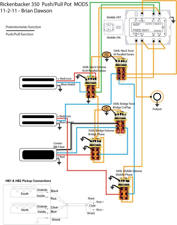 My caveman electrical knowledge goes only so far... I don't think the M phase CAN be placed to work with M in series. unless we start the whole chain there, but then how will the B coilcut and phase fit? I agree its better to have independent volumes for all settings. |
|
|
|
Post by JohnH on Nov 2, 2011 14:14:46 GMT -5
Its coming along!
Just on that M phase switch. You should be able to have it active in both series and parallel if you wish. Just take the pickup red and blue wires straight into the phase switch before they go anywhere else, then two wires out of the switch to go onwards to the rest of the circuit.
John
|
|
bdawson7
Rookie Solder Flinger
Posts: 16
Likes: 0
|
Post by bdawson7 on Nov 2, 2011 16:17:46 GMT -5
Thank you thanks thanks! ;D Mid phase should now work in parallel and series. 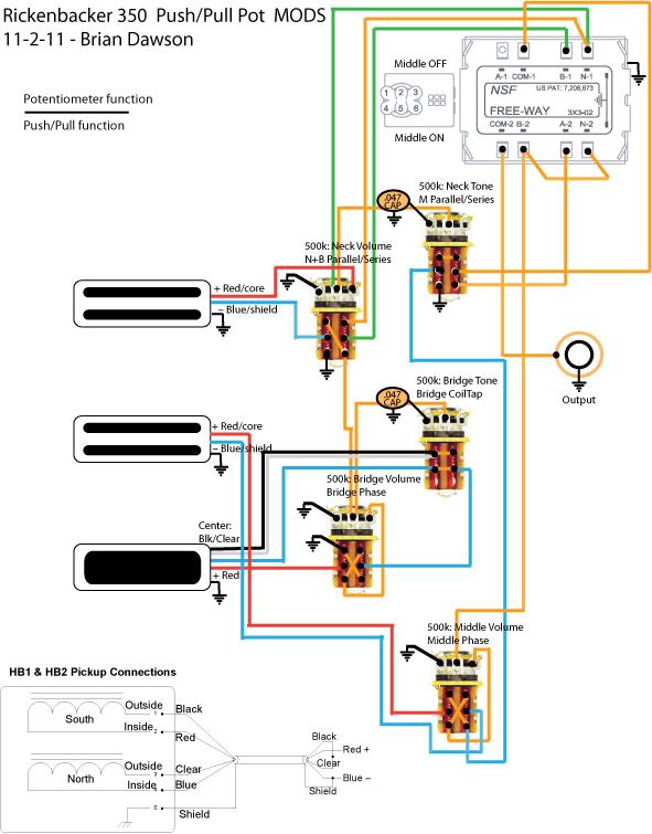 |
|
bdawson7
Rookie Solder Flinger
Posts: 16
Likes: 0
|
Post by bdawson7 on Feb 4, 2013 21:45:47 GMT -5
Another year older and deeper in debt.... Now that I'm closer to actually building this, I took another look at it. Thanks to JohnH's JHJP design for some ideas here; I'm currently updating my LP with that design. I designed this to use only the existing 5 pots and one switch on a RIC pick guard. I've got what I've been after: All pickups on/off separately B+N series N+M series (now Hum-bucking) Relative Phase between all pickups (B & M phase switches) B Single coil And like a late birthday card, some nice extras: Freeway switch adds Middle easily into any other combos Entire guitar in parallel, and switchable into full series Adjustable volumes in all series modes No dead spots when using series modes B Phase switch will change coils when in BSingleCoil mode Humbucker when N+M in series *Humbucker when BSingleCoil + M (not positive on this yet, don't know HB polarity vs. SC; can move HB wires to get it, though, ala "inside-out" wiring) Downsides: No B+M series (but B+N is a more obvious difference in tone, and closer to the bluesey tone I'm after) No N phase for quick switching (but the other 2 switches accomplish the same thing) Need to start with little bit of surgery: 1. Cut the shield away from the ground lug under each of the single coils, and put a new ground wire in place of it, soldered to the lug. Be sure the leftover shield doesn't touch anything (tape it up). 2. To make the Middle SC into RWRP, remove and flip each of the 6 magnets. Directions here: palka.com/rickpick.html No need to remove wires as he shows (unless replacing them with 4-core/shielded).... Existing wires can be used as noted where the diagram says "+Red/core" or "+Red/shield". I'll probably use shielded wiring from pickups, replacing SC wire w/4 conductor Shielded (unless there's a 2-conductor + shield out there, but I haven't seen it). One deal-y: 1. As mentioned previously in the thread, volume pots wired like this are interactive (one of them at zero can turn off the whole guitar), but may sound better with 3 pickups. I prefer non-interactive/"backwards" wiring. How drastic is the difference? Do I need to un-ground the volumes? B. Is 500k enough when in all-series mode, as all the signal is going through the mid volume pot? Anyone see another? 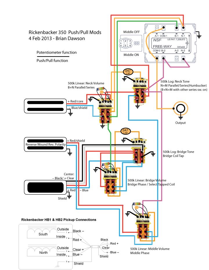 |
|
|
|
Post by newey on Feb 4, 2013 22:53:43 GMT -5
Welcome back, Mr. Dawson! It's a bit late to sort through the latest diagram at present, but it looks like you're well along with this. To give credit where due, the JHJP scheme is JohnH's design, not mine. Also, I see where your Ric draws inspiration from the Page and May wiring, but where does Ms. Hoffs fit into the picture? |
|
bdawson7
Rookie Solder Flinger
Posts: 16
Likes: 0
|
Post by bdawson7 on Feb 4, 2013 23:08:08 GMT -5
Ah, JohnH! (Tha'd be the JH of the JHJP) Edited....
The lovely Ms. Hoffs' guitar is the starting point for this, with the HB and 2 SC on a 24-fret Ric 350. I've always been attracted to its look, and I need to get my 350 refinished with binding, then add this electronic setup.
|
|
|
|
Post by JohnH on Feb 5, 2013 4:27:28 GMT -5
Nice to see you again!. I just had a look back and see we had a few iterations a year or so back. Theres lots to check but the main issue I see is that the pots all have grounded lugs, which will mess up things in series mode. See my post no 16 and earlier sketch. You can get two core screened bable in the form of normal microphone cable. Or, many audio cables for stereo have two cores or two seperate ones in a figure of 8. USB cable was suggested recently for 4 wire conversions. On your volume pots, I see you are listing linear pots with treble bleed. The treble bleed resistors tend to further flatten the taper, turning a log pot halfway to linear. So if you still have an option, Id suggest log pots. For the basis of the series wiring, you might be interested in these tests: blending coils in series cheers John |
|
bdawson7
Rookie Solder Flinger
Posts: 16
Likes: 0
|
Post by bdawson7 on Feb 11, 2013 20:15:23 GMT -5
Thats a great test, thanks John. And thanks for the other notes, your other diagrams have really helped me out a ton! I was missing the whole concept of the grounded lug/pass through. Think I got it here. I have reworked the positioning of the controls to mimic a les paul volume & tone layout, and logical (to me), i.e., Jimmy Page, layout of push/pull functions. The two Series/parallel switches might eventually trade places from what is shown on this diagram - see how I feel by the time I build it. So this might be the last diagram for this HSS, it seems to finally have all I was looking for. Now to find all that money I've been looking for. ;D 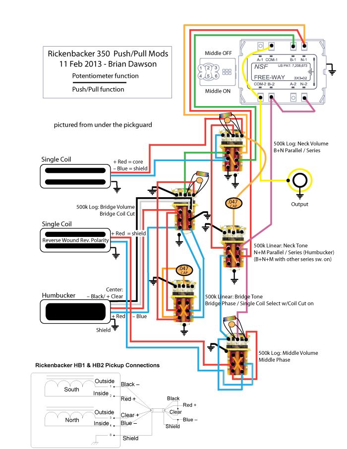 |
|
bdawson7
Rookie Solder Flinger
Posts: 16
Likes: 0
|
Post by bdawson7 on May 7, 2013 9:29:43 GMT -5
An update, and a question/problem... I realized I want to use the tone control on the whole humbucker when N+M is in series. Then the signal chain becomes Gnd..M..N..B in the second diagram (to retain B+N series and N+M using Ntone) the reverse of what I had originally. So... 1. Is it ok to have the RWRP Middle SC start out the signal chain? I thought it was cw to always end with RWRP. 2. Will the Coil Cut still work in series mode? (Indigo-colored "Z" line in dead-center of diagram 2) The negative from one coil (black) and positive from the other (clear/gray) goto ground when in parallel, but when in series it goes through the other pups. IOW, Does the +(clear/gray) going through pups make bad-ness? I'd like to keep the coil-select function of the phase switch when in CoilCut; these are taken from the JHJP. UPDATED Original: Switched position of parallel/series controls: 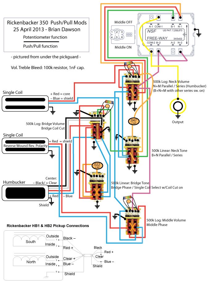 QUESTION: Re-wired to use N tone on N+M in series mode: 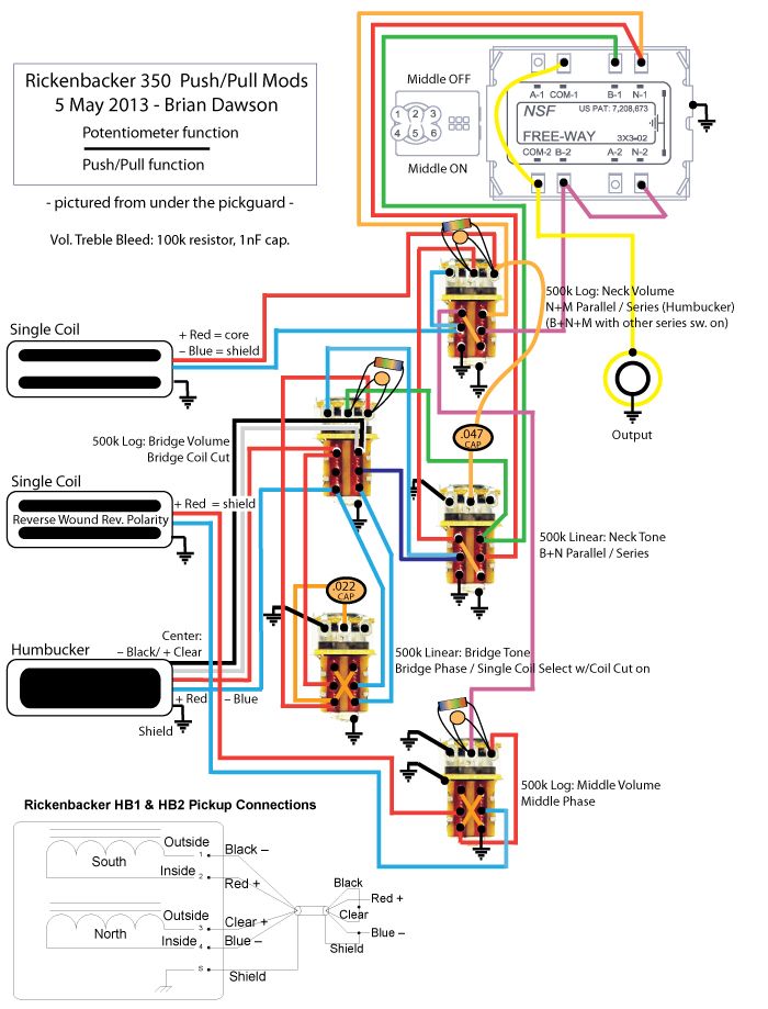 |
|
bdawson7
Rookie Solder Flinger
Posts: 16
Likes: 0
|
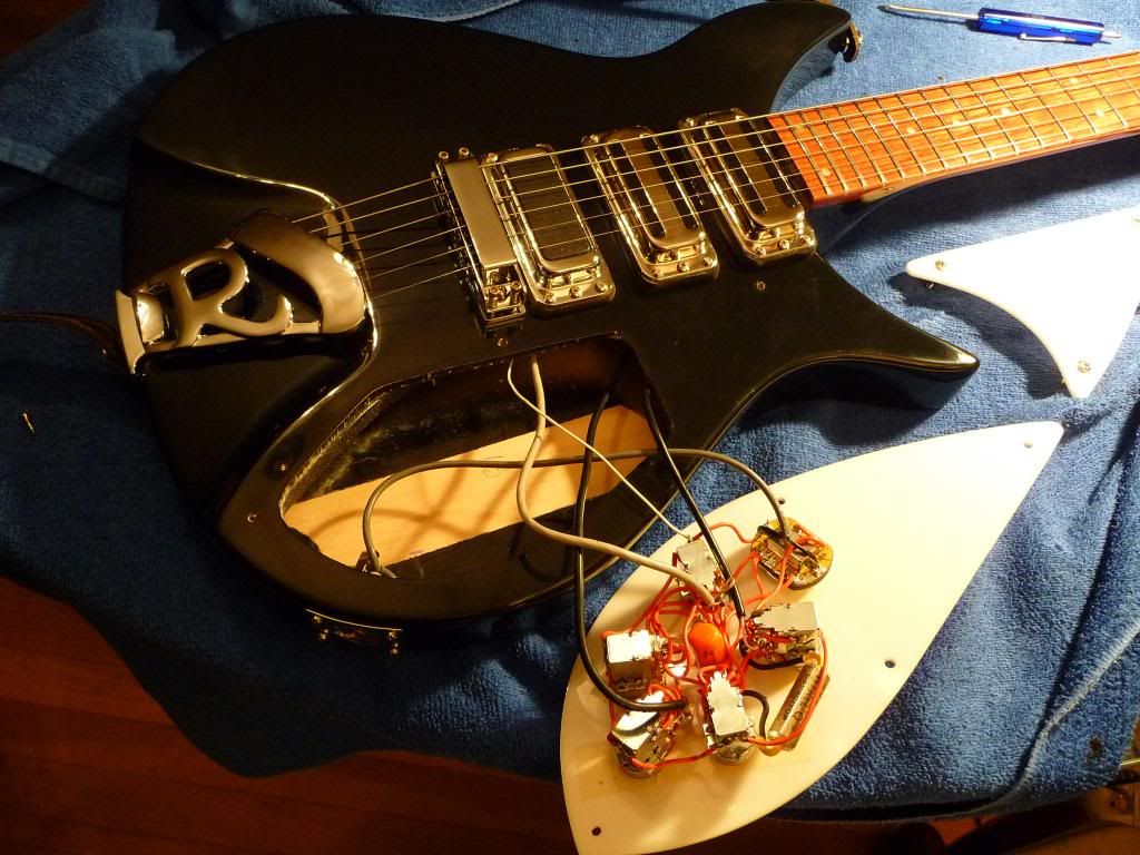
Post by bdawson7 on Mar 19, 2014 18:44:41 GMT -5
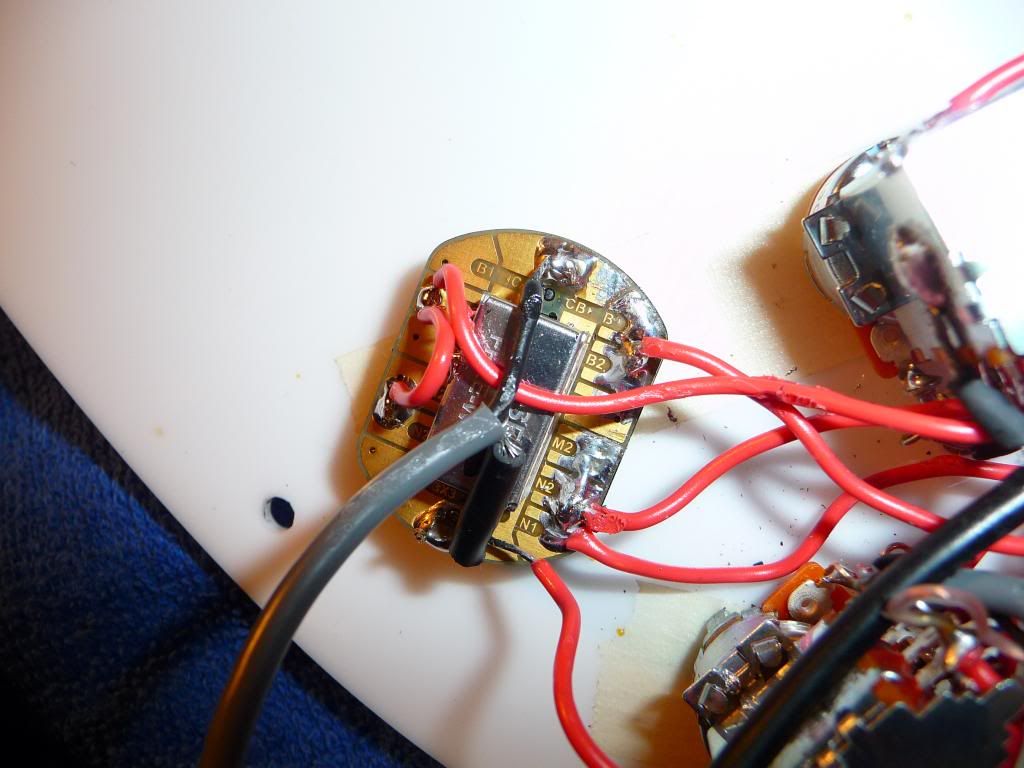
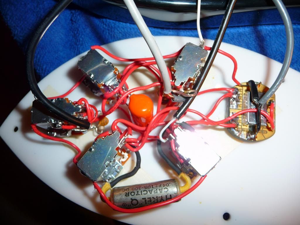
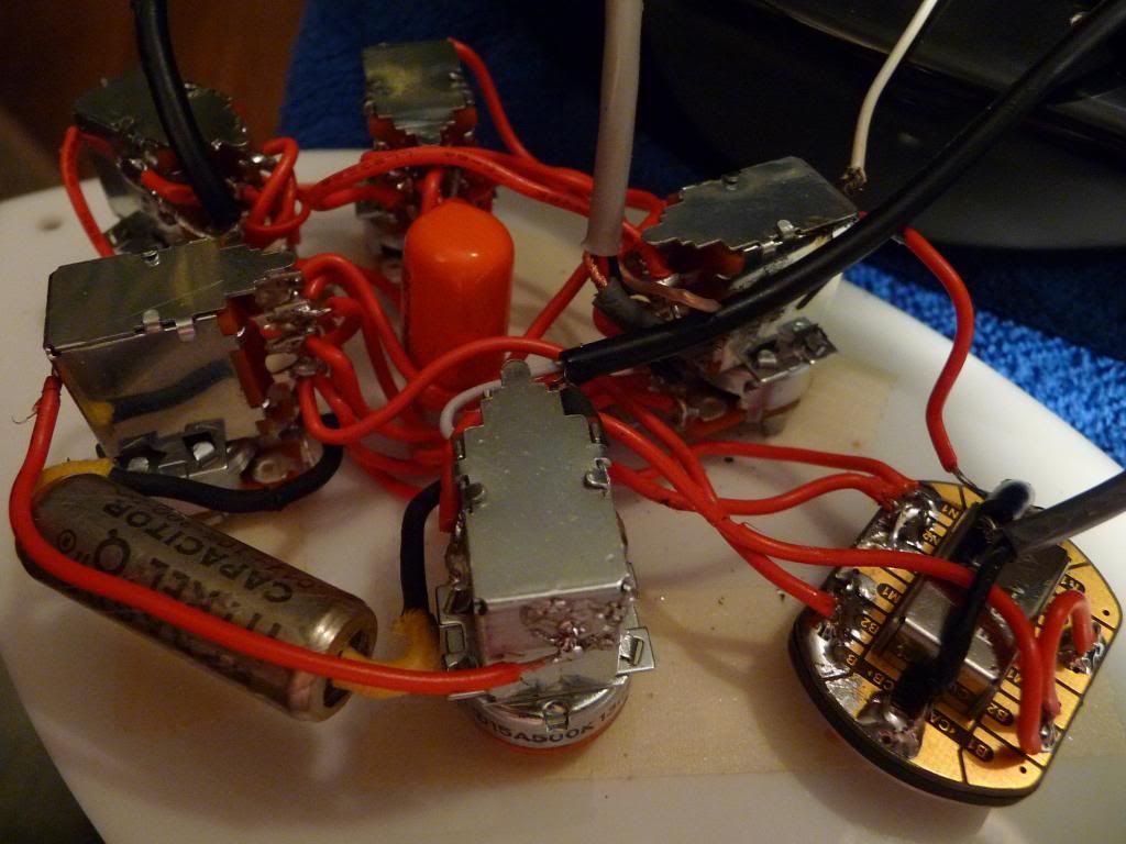
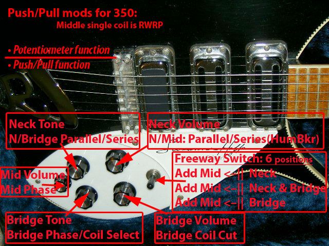
Thank you to everyone on the GuitarNutz 2 board. I finally finished this mod. It works, and sounds fantastic. Long story definitely *not* short, and I hope this helps anyone that might be thinking of doing it, with info as if starting from zero, which I would have found useful. (crossposted to RickResource.com) My Rickenbacker 350 Liverpool from 1995 had 3 of the mid period Hi Gains - the pole pieces without any hex holes. I have no major tooling nor a vice, so I used hand tools and a Dremel to remove the button tops of the pole pieces in order to put toaster tops onto the Middle and Neck. The reason I did all this work to my existing pickups instead of some current models with more easily removed hex-pieces is because the black plastic toaster "holes" on these do not have that extra little circle of plastic on each end. I think its a cleaner look. Looking back, I should have sent them out to have countersunk flat-top screws put in.... but then I couldn't have had all this fun! Disassembly After moving the R-tailpiece away (with all the loosened strings attached) and removing the pickguard, I cut the pickup wires at the control assembly. I took out the pickups and removed the top & bottom pickup covers to free the bobbin, and cut the thick shielded extension wires as far from the bobbin as possible, so I could easily reattach my wire later. I then cut through the glue around the magnet edges with an exacto knife. The magnet itself is really soft, and I could have easily cut chunks of it off. There was a good amount of glue actually under the magnet, and I slid the knife right under to free it up. Some of the magnet material was still held by the glue, I scraped it off the bobbin. Had to be really careful to avoid cutting through the wires in the center and the corner, they're really small. The first time, I actually did cut the corner wire, flush with the bobbin. Yipe! I carefully took the shielding tape off to see the end of the connection wire itself, and saw there was actually some slack on the ultrafine-guage winding wire based on the wrap direction, so I could pull the thicker connection wire out about 1/8" to get some length to work with. That was a huge pain, dealing with that small wire with tweezers - do whatever you can to keep some of the preexisting extension wire. Here's a diagram of the wrap direction. The yellow extension wire runs in the opposite direction of winding, and the winding wire is spiraled around it like a corkscrew and soldered to it. 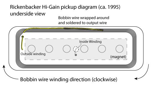 Once the magnet was off, I placed the bobbin on the inside edge of a roll of duct tape (!), and pounded out the pole pieces from the underside using a finish nail press I had, one that has a spring-loaded sheath and is made to set a finish nail into a wooden molding without slipping. This has no taper, as an awl does, so I thought it would be better for getting straight through the bobbin. Turns out that bobbin material is super strong and really held the pole pieces in there. I was hammering really hard to get those pole pieces to budge, with a force that I was worried would damage the bobbin. Seems like its made of a very hard but porous plastic that was formed around the pole pieces already in place. Pole pieces have a really coarse threading (deep cuts in the threads - looks like a star when viewed from below), and thread pitch - what seems like one revolution to almost 1/2 inch of travel (very coarse). Later it seemed like I might have deformed some of the threads inside the bobbin while pounding out the pieces, because it was more difficult to screw the pole pieces back in. If I had a vice to hole them securely and therefore could tap more precisely, I think I would have avoided that thread deformation, since the pieces would have rotated slower on the way out. Pole Pieces I used a pair of locking pliers to hold the bottom end of the pole piece while I cut off the button top, and then cut a groove for a flathead screwdriver on that top end. I put the pliers on the edge of a bench to hold with one hand and the Dremel in the other hand. The pliers ended up being a bad idea, because they deformed the ends of the threads on some of the pole pieces, making it very difficult to use a screwdriver to get them back into the bobbin. Several of the ends were too sharp and grabbed the bobbin material too much to get back into a smooth groove. The screwdriver then ended up mangling the screw end, and I had to pound them back in from the top, the same way I pounded them out. The Dremel cutting wheel was too thick (about 1/8"), I think, because it took away alot of the metal when removing the button tops, and didn't leave enough when making screwdriver slots, so that the remaining sliver of metal deformed under pressure from the screwdriver. I pounded or screwed in all the pole pieces until they were flush with the bottom of the bobbin, putting the slightly taller ones at the center, to account for the neck radius, but it was a difference of only 1/16" or so, not very much. All of the tops of the new cut pieces ended up below the top edge of the bobbin. When this pickup is built in the factory, it looks like the bottom (magnet) side of the bobbin is ground down to make the ends of the pole pieces flush with the bottom of the bobbin - I saw residual sanding/grinding marks. However the magnet does not end up exactly flush and touching the pole pieces. The center wire comes out of the bobbin slightly below the actual center of the bobbin, and the hole that is centered in the magnet doesn't line up with this, so there's a tiny distance between facing surfaces of the magnet and bobbin. There was also glue in this area. When I re-assembled them, I pushed the magnet tightly down onto the bobbin in the same place it was before, secured with a rubber band and glued around the edges, but there was still air between the magnet and bobbin. RWRP Before I started, I marked the visible outside of the magnets "same polarity." For the Neck pickup, I just put it back the way I found it, "same polarity" mark facing out, and put a small bead of epoxy around the outside edges of the magnet. For the Middle pickup, I put that "sp" marked side facing the bobbin, to make it Reverse Polarity. Then I connected about 12 inches of the same 2-conductor & shield wire to both pickups. For the Neck, I connected using the original wiring method: red + is the outside bobbin wire (corner hole), blue — is center bobbin wire (center hole, out from center of the magnet), shield is ground, soldered to the washer screwed onto the corner of the cover (Originally, — and shield were soldered together; 2-conductor & shield wire makes it possible to separate these to use series and phase switches). For the Middle pickup, I swapped the + and – from the standard locations, which now finally made it RWRP. In other words, the red + wire on the RWRP pickup comes out of the bobbin where the — comes out of the normal pickup (center hole), and then treat it as a normal red + when hooking up to the rest of the guitar. Final Assembly & Operation The Freeway switch 2.0 works great. I don't have experience with the V.1, but this one came from Stewmac (designed in UK) with 3 color tips, (cream, amber, & **black**), flat solder-attracting pads on the back, and small footprint. It switches smoothly, doesn't stick, and you should know where you're switching, since its not just up-n-down. It seems pretty strong, but I'm not about to hit it to see if it will break. I followed the wiring instructions, and hookup was a breeze. The DiMarzio 500k audio push/pulls just fit the cavity depth (there is no lower tab that adds 1/16" like on Alphas), and replicate the firm turning action of standard RIC knobs. They are a narrower diameter in the mounting shaft, however, and need strong tightening on the mounting nuts to hold them well enough to the plastic pickguard. The knurled ends fit the RIC knobs and allen screws fine without added sleeves. After a while I've gotten used to the resistor-altered tapers on the volumes, seems like they're doing everything between 0-3, whereas the original RIC pots were a perfect taper. I may take off the resistors to see the difference. The tone controls are more interactive than I expected. The tone control of any active pickup will affect the entire sound when in Parallel mode. So whenever N is active on the Freeway, its tone control will effect the whole output, and ditto for B. I see two good things about it: 1. I have two different cap values to play with, & B. Huge sound changes are possible with one switch change. When in all-series mode, the signal path is M->N->B. The tone controls affect only the pickups before them in the series. But if B is parallel to M+N in series, then N tone will still affect B because B is in parallel. Slightly confusing, but neat effects are possible because I can use both caps at once for an ultra-cut, or different cap on either pickup (The N pickup is pretty dark, so I'm going to switch the existing .047 cap for a brighter .010 to keep some mids). Humbucker Diagram Mistake? The face of my remaining unaltered factory Hi-Gain is attracted to what is labeled by RIC in the diagram as the South pole face of the HB; the RWRP face is attracted to the North. Opposites attract! Therefore I thought the factory standard polarity of my 1996 Hi-Gains is North facing up, toward the bobbin, based on the new RIC Humbucker I have, its diagram, and the attraction/repulsion of the Hi-Gains to the two HB poles. I thought I needed the Humbucker's North coil to be active, when I pulled the coil-cut switch to make use of the noise canceling of the Middle RWRP pickup (Neck:N - Mid:S - Bridge:N). I wired it so the North coil, based on the pin numbers on the RIC diagram, would be active. All the HB wire colors IRL corresponded to the RIC diagram. When I finally plugged in to check the system, the whole HB was out of phase with the rest of the guitar. I swapped the Black and Clear wires at the coil-cut switch and then it sounded as expected when switches were in all the different positions. Now the active coil in coil-cut mode sounded like it was the one closest to the bridge, with a too-harsh tone in single-coil solo mode, compared to the other coil. I spun the HB around 180º with the wiring pad away from the pick guard, on the left side of the HB when looking down from the top, so now the active coil is farther from the bridge, and is a good approximation of a HiGain. When I pull the phase/coil select switch to activate the coil next to the bridge, its a little harsh in solo, but that plays well when combined, opposite phase, with the other pickups. Was I reading the diagram wrong? I was looking at the pickup from the top, string side up, wire pad to the right, all colors were the same as IRL. Is the N/S +/– labeling on the diagram wrong? Are all RIC HBs wired out of phase? Here's my final as-built diagram. The HB-1 diagram is straight from RIC, uncorrected. 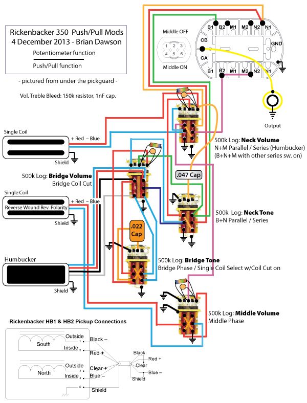
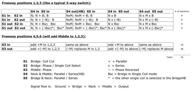
*** Signal flow as built is: Ground > Middle > Neck > Bridge > Output ***
|
|
bdawson7
Rookie Solder Flinger
Posts: 16
Likes: 0
|
Post by bdawson7 on Mar 19, 2014 19:02:42 GMT -5
|
|
|
|
Post by JohnH on Mar 20, 2014 1:42:22 GMT -5
Congratulations on finishing it, welcome back again, and thankyou for the detailed post.
Hoping that you have had many other adventures between appearances, like a comet in our night sky, each time brighter than before!
So what are the best new sounds that you have found?
|
|
bdawson7
Rookie Solder Flinger
Posts: 16
Likes: 0
|
Post by bdawson7 on Jul 25, 2017 10:50:43 GMT -5
Photobucket is getting constrictive and may someday disappear. All the files in this post are now on imgur.com here: My account: bdmd777.imgur.comAlbum: imgur.com/a/5TMrJYou will probably only want to see the last few files for the final result, and not the brainstorming over the years. Here is the guitar today, after an astounding makeover this year by Larry Davis in Florida. davisguitarworks.com   ![]()  |
|