apafaf
Rookie Solder Flinger

Posts: 6
Likes: 0
|
Post by apafaf on Nov 18, 2011 19:55:35 GMT -5
Hi! I got H-S-H in my Strat with regular wiring and want to install DPDT switch to get H-H serial wiring as 6th combination of pickups. I'm very new in this and want to learn so I made one diagram where i draw how it can be made in my opinion and here it is : 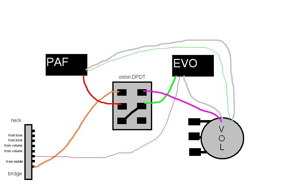 So, can anyone tell me is this good or not? Thanks!
(EDITed by sumgai to make the image directly viewable.) |
|
|
|
Post by newey on Nov 18, 2011 21:06:36 GMT -5
apafaf-
Hello and welcome to G-Nutz2!
Without any of the other wiring on the 5-way switch (and without knowing which lugs are which on the switch), it's difficult to tell if you're on the right track here or not.
But from what I can tell (and I'm unsure of this, so don't take this as gospel), it looks to me as if your DPDT switch will put the two pickups in series, but only when the 5-way switch is set to positions 1 or 2; with the DPDT pulled and the 5-way on 3-4-5, you'll get nothing, since the "series chain" isn't connected to output.
But again, just a guess.
I suspect the issue can be easily solved, though.
|
|
|
|
Post by cynical1 on Nov 18, 2011 21:20:58 GMT -5
Just as an aside, and not exactly related to your question, but for me, I set my pickups with an individual series\parallel toggle. This give you the option to choose either option for the pickup regardless of what else it's tied into it.
For example you can have both pickups in series or parallel together, or neck parallel and bridge series, or neck series and bridge parallel. There is a difference in the nuances. Granted, it's an extra toggle, but for me I find it very useful and worth the extra hole.
But that's just me.
And I agree with Newey, it'd be a lot easier to give you a definitive answer if we knew what the entire scheme was.
Happy Trails
Cynical One
|
|
apafaf
Rookie Solder Flinger
Posts: 6
Likes: 0
|
Post by apafaf on Nov 19, 2011 6:29:46 GMT -5
Here is entire scheme : 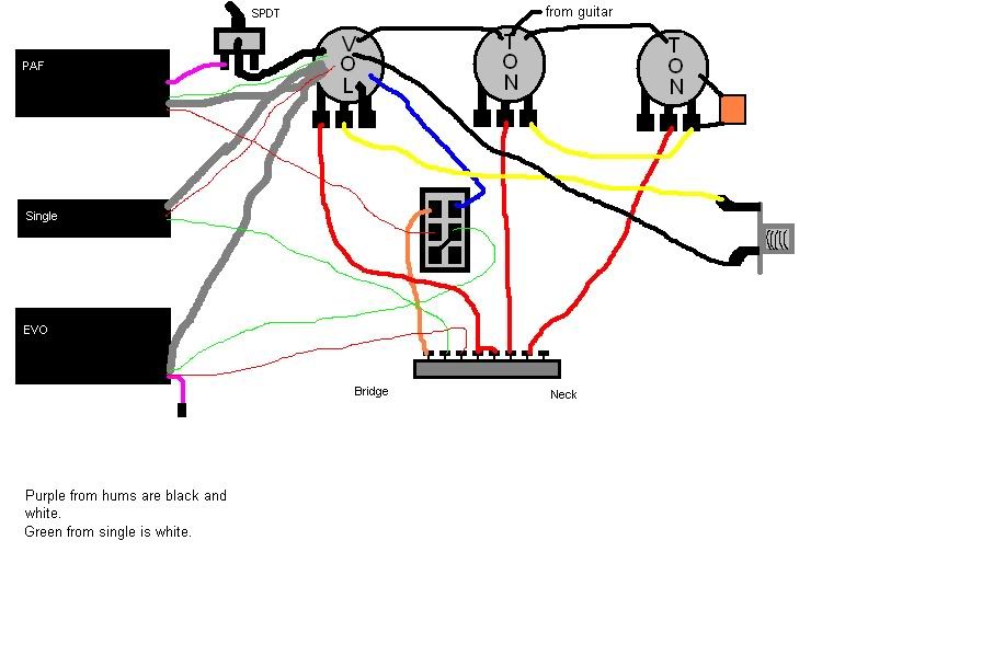 All I want to do is to have hums in series wiring when the DPDT switch is in first position and 5 way switch in position 1 and when it's in second position to have normal 5 way switching. Red from PAF and green from EVO are connected to the middle lugs of the switch (B and E), from A goes to 5 way switch. I hope this helps... I thought about installing individual switches for each pickup but it's just an idea, nothing serious yet... I need to do some experiments with wirings and after that I will know what I need. For now I'm sure that I need two hums in serial.  Thanks. (EDITed by sumgai to remove the horizontal scrolliness.....) |
|
|
|
Post by newey on Nov 19, 2011 8:48:58 GMT -5
If we call the bridge position as "position #1" (which is a fairly standard way of naming them), then that's what you've got.
As I said originally:
Note that you will get series in either position 1 or position 2, not just in position 1. And it'll be dead with the knob pulled in all other positions of the 5-way.
So, if that's what you want, you're good to go with the diagram you have.
But, again, there may be a more functional way to do this. Opinions vary (and to each his/her own), but for me personally dead spots are a deal breaker.
|
|
apafaf
Rookie Solder Flinger
Posts: 6
Likes: 0
|
Post by apafaf on Nov 19, 2011 9:19:25 GMT -5
I knew that when this switch is in position for serial hums I wouldn't be able just to switch for example on neck because I breaked its connection to the 5 way switch. And there's also one big problem that's tracking me always - I don't really know so much about wiring.  I had idea to wire DPDT somehow trough the 5 way switch, then I guess it would be possible to do normal switching when DPDT is working for serial hums but I don't know how works 5 way switch, but I found some pictures of possible connections in every position so I hope I will came up with some new diagram. And if anyone got some site address with explanation of 5 switches and all other stuff I would be gratefull if I get it. Thanks for everything! |
|
|
|
Post by newey on Nov 19, 2011 17:21:17 GMT -5
|
|
apafaf
Rookie Solder Flinger
Posts: 6
Likes: 0
|
Post by apafaf on Nov 20, 2011 21:35:02 GMT -5
Can someone please check is this diagram ok : 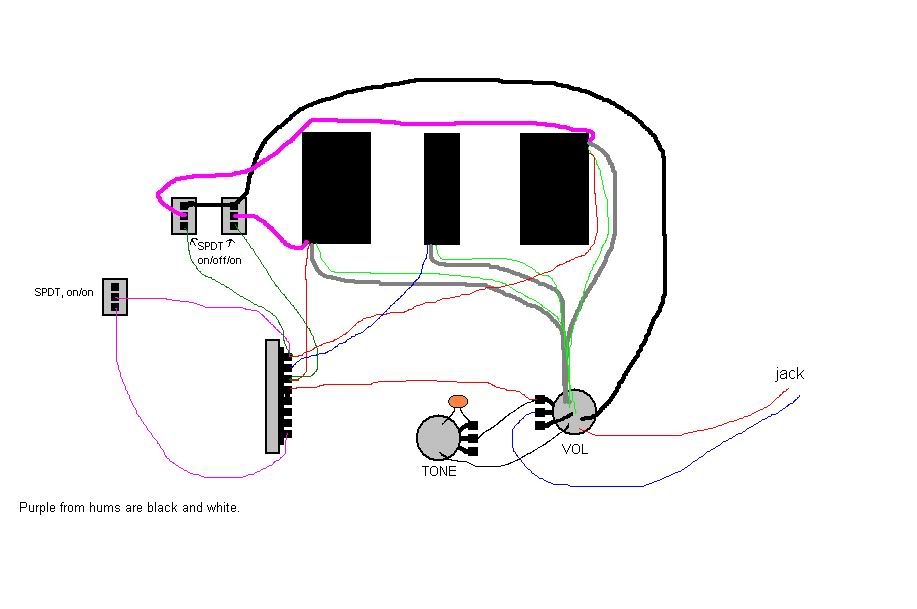 Should be this : 1.bridge ( when on/on switch in position 2 then bridge and neck parallel) 2.bridge + middle 3.middle 4.neck + middle 5.neck Should be able to split both hums on both coils. So...? |
|
|
|
Post by newey on Nov 20, 2011 22:04:25 GMT -5
Your diagram is a bit tough to read, but I think that will work as advertised. But the problem is I can't tell which pickup is the neck and which is the bridge. If the bridge pickup is, as I suspect, located closest to the jack in your picture, then you're adding the bridge in parallel with the neck at position 5, not adding the neck to the bridge at position 1. Either way is equivalent sonically, it just depends on where you want to do the switching. But again, it should work as is.  |
|
apafaf
Rookie Solder Flinger
Posts: 6
Likes: 0
|
Post by apafaf on Nov 21, 2011 7:40:32 GMT -5
Glad to hear that works! Bridge pickup is located closest to 5 way and I want to add neck in parallel at bridge position ( that was on my mind, at least). Ok than, this goes into my guitar. Thank you for your help! |
|


 Thanks.
 I had idea to wire DPDT somehow trough the 5 way switch, then I guess it would be possible to do normal switching when DPDT is working for serial hums but I don't know how works 5 way switch, but I found some pictures of possible connections in every position so I hope I will came up with some new diagram. And if anyone got some site address with explanation of 5 switches and all other stuff I would be gratefull if I get it. Thanks for everything!