|
|
Post by kemikalhalo on Apr 1, 2012 17:36:35 GMT -5
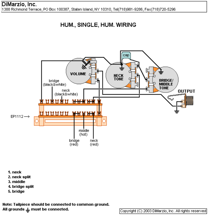
Howdy experts! I just refinished a MIM Strat body that I rescued from someone who did a really bad job trying to relic it. I am throwing a TV Jones TV CLassic in the neck, TV Classic plus in the bridge and a Seymour Duncan SLS1 reverse wound reverse polarity single coil lipstick tube in the middle position. I have a Fender 4 pole superswitch, S1, and two 500k pots that I am going to use. I found the below wiring diagram that gives me all the options I wan't but I would like to add a second tone pot to the setup, but alas I am a noob when it comes to wiring and looking for advice as to how accomplish that. I am also wondering if I am going to run into any issues with the RWRP Duncan in the middle position with this diagram. Would I accomplish the second tone pot by removing the bridge between the two common lugs and wiring one tone first tone pot to the right side common lug for the neck and the second tone pot to the left common lug for the bridge? Something tells me it couldn't be that easy. As for any phasing issues I can't even begin to speculate. Thanks for knowledge you can pass on.  Diagram originally found at: sites.google.com/site/phostenixwiringdiagrams/hsh-guitars |
|
|
|
Post by newey on Apr 1, 2012 19:57:20 GMT -5
kemikalhalo-
Hello and Welcome to G-Nutz2!
The two things you mentioned, the RWRP middle and the second tone control, both present some potential issues.
First, the question about the RWRP middle pickup. The diagram you are using assumes that you're using all SD pickups- but you've got 2 TV Jones and one SD. Mixing pups from different manufacturers requires testing for the magnetic polarity between the middle, and each of the coils on the HBs.
This won't matter except when your S1 switch is "up", which gives you the coil-split positions on the HBs. The SD diagram is set up to give the inside coil on the Bridge pup with the neck, and the outside coil of the neck with the middle. Those coils were chosen for a reason, so as to be hum-cancelling with the middle pup.
You might get lucky, and the magnets on the TV Jones might be exactly the same orientation as the SDs, but it's best to check to be sure rather than trusting to luck.
You will want to put the middle pup face-to-face with each coil of each HB. Opposite coils buck the hum, and opposites attract- so you'll want to see if the TV Jones pickups attract the middle with the neck outer coil (the neck inner will then repel the mid pup) and the inner of the bridge should attract. If so, they're identical to the SDs and you don't have to worry about it further.
If not, you'll need to revise the diagram so as to select the other coils on each HB for the split-coil positions. We can help with that if necessary.
As for the extra tone control, do you want one tone control for the bridge HB and another for the neck? Meaning no tone control on the mid pup? If so, you would wire each tone control "across" its respective pickup- the tone pots will each be the first component in line after the pickup, and before the switching.
Now, if that's not what you want- if, for example, you're thinking of a separate bridge tone pot and a master tone- you may have some problems with 2 tone pots being in circuit at once.
In any event, your idea to disconnect the "common" lugs and insert the second pot won't work. The two pots will interact with each other, and the added resistance of the two in parallel will dull your tone.
Now, if you wanted one tone for the bridge pup, and another for both the mid and neck together, that might be viable, I'd have to take a look at whether the 5-way superswitch could be reconfigured to accommodate that.
In any event, we'll need more specifics about what you want out of the dual tone controls.
|
|
|
|
Post by yakkmeister on Apr 1, 2012 19:59:28 GMT -5
Hey Dude! Welcome to the forum! I am pretty new and I don't know a millionth of what some of the other guys here know ... But here's a stock diagram 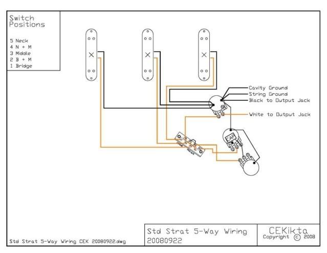 It's from here: guitarnuts2.proboards.com/index.cgi?board=stock&action=display&thread=6268Looks like you will want to couple the 3rd pot off the existing tone pot... I don't see where the connection to the switch goes though, and that will depend on what combinations you are expecting the 2nd tone pot to control, I guess ... It also looks like the volume pot is decoupled from the tone pot respective to your diagram. That's all I have, I am afraid ... |
|
|
|
Post by yakkmeister on Apr 1, 2012 20:08:06 GMT -5
|
|
|
|
Post by kemikalhalo on Apr 1, 2012 20:52:47 GMT -5
Thanks to everyone who replied! I've been reading through a lot of posts on here and I am learning allot!
This is exactly what I'm looking for. I follow what you're saying but I have no idea how to go about doing it or what lugs on the pots I would have to hook to which wires from the pickups and then from lug on the pot to the switch or which lug on the pot I would have to attach my cap to. My assumption would be the outer lug for the cap and the middle lug for the wiring, but I have learned not to assume anything.
This is awesome information! Hopefully I will get lucky and it will be the same. If the are different though is it a matter of swapping the north and south start locations where the mismatches are?
Thanks again for the input, this forum is awesome! SO glad I stumbled upon it!
|
|
|
|
Post by newey on Apr 1, 2012 21:45:53 GMT -5
Close to that. Look at the SD diagram and notice how the HBs are wired. They are not identical, and the reason for that is to select the appropriate coil to combine with the middle. On the diagram, first trace the red and white wires from the Bridge pickup (remember, these are using the SD wire colors) to the 5-way switch. See how the two wires are joined at one of the common poles of the switch? This junction forms the "series junction" between the two coils. We'll call using the red/white pair as the series junction the "standard HB" wiring (for SD colors, again). It's not really "standard", but we need to specify it somehow in order to talk about it intelligently . . .  Now look at the neck HB. Instead of the red/white wires joining at a switch pole to form the series junction, the green and black wires join instead. And the red and white wires, which formed the junction on the bridge pup, are the output wires. Our member wolf has termed this arrangement as "inside-out" wiring of a 4-wire HB, and it's as good a name as any. So, to get the specific coils for this scheme, SD wired the bridge pup as "standard" and the neck pickup "inside out". To get the opposite coils then, if needed, you would wire your TV Jones such that the neck pup was wired "standard" and the bridge "inside out". Of course, you would first need to correlate the TV Jones wire colors with the SD colors. As for the tone pots, check out the way the tone controls are wired for any 2 HB guitar with separate V and T controls (LP, SG, etc.), Your tone controls will get wired the same way. For clockwise (right-handed) operation, the "hot" wire from the pickup would be attached to the clockwise lug on the pot, and would also go from there to the switching. The tone capacitor would be attached to the center "wiper" lug of the pot; the other end of the capacitor is grounded. The third lug of the pot, the CCW lug, is left unwired. If you're a lefty, reverse the above. |
|
|
|
Post by kemikalhalo on Apr 2, 2012 20:21:39 GMT -5
Thanks for the explanation, I think that gives me enough to figure this out for myself and troubleshoot issues if I mess it up somehow. Once the rest of my parts are delivered this week I'll take a stab at it and let you know how I make out.
Cheers!
|
|
|
|
Post by reTrEaD on Apr 5, 2012 7:47:44 GMT -5
I think some poor choices were made in the design of this circuit. Both in selection of which HB coils to combine with the middle, and the efficient use of switches. Look at the SD diagram and notice how the HBs are wired. They are not identical, and the reason for that is to select the appropriate coil to combine with the middle. From a hum-canceling point of view, one HB has the "appropriate coil" selected, the other does not. IF this were a matter of combining one coil from a HB and one coil from the other HB, "inside out" wiring would make it easy to get two dissimilar coils. One north and one south will hum-cancel. But that combination NEVER occurs in this circuit. The only time the two HB are combined it when they are both used as full HBs. The combinations involving split HBs are with a HB and the middle pickup. The HBs should BOTH be wired the same way. Either both normal or both "inside out", depending on the magnetic polarity of the middle pickup. The wiring for splitting the HBs is wasteful in terms of the number of switch sections used. One section of the S1 and TWO sections of the superswitch are used. The necessary tasks could be accomplished with two sections of the S1 and NO sections of the superswitch. Or it could be done with one section of the S1 and one section of the superswitch. This would leave at least one, if not two sections of the superswitch available for other tasks, such as selecting which tone control is enabled. |
|
|
|
Post by newey on Apr 5, 2012 15:54:33 GMT -5
RT's right, I was thinking about it wrongly. Again, using dissimilar pickups, you'll need to check for polarity, but you'll want to find the opposite coils to the middle for each HB, which should be the same coil, N or S, for both HBs.
|
|