spaceangel
Rookie Solder Flinger

Posts: 10
Likes: 0
|
Post by spaceangel on Aug 28, 2012 20:06:14 GMT -5
I have a guitar with 2 humbuckers,a 3way switchcraft toggle,and a master vol.and tone.What I would like to do is install a switch[mini toggle or push pull pot]that will : bypass the 3way and
tap the inside coils and put them in parallel
this is the only sound I want to add to the existing configuration.I don't want the option of either HB alone in SC mode-thanks in advance |
|
|
|
Post by reTrEaD on Aug 28, 2012 20:39:25 GMT -5
It won't be pretty (it will leave outside coil(s) hanging from hot), but it can be done. If you'd like a diagram, indicate what brand pickups you are using (for wire color codes) and how your pickups are oriented (both slug coils inner or some other orientation). It makes more sense to use one screw coil and one slug coil (for hum-canceling), but the wiring can be designed however you choose.
|
|
spaceangel
Rookie Solder Flinger
Posts: 10
Likes: 0
|
Post by spaceangel on Aug 28, 2012 21:13:44 GMT -5
they are stock pickups in a peavey predator exp.both slug coils are inner now and are the same magnetic polarity.I figured I'd either have to flip a magnet and reverse the hot and ground or just turn one pickup 180 degrees to get hum cancelling in the split mode.Mainly just hung up on the switching config.Was hoping DPDT would work-thanks
|
|
|
|
Post by JohnH on Aug 28, 2012 21:42:37 GMT -5
DPDt can work, with the warning that retread stated. The unused coils would stay connected with one end to hot, so small but significant risk of extra noise.. If you can use a mini toggle, you could get one with 3 or 4 poles instead of 2 - then this issue can be avoided. Wire your hb's with the coils you want on the hot side and the ones to be cut out towards ground.. Then, two poles used to ground each HB centre connection, leaving each as the relevant inner single coil. Third pole connects both outer main-toggle lugs togther, making the toggle position redundant and forcing both pickups on.
J
|
|
|
|
Post by reTrEaD on Aug 28, 2012 22:59:42 GMT -5
Yep, 3 poles is definitely the preferred way to go. Here's the 2 pole version with the inners as both slug coils. If one pickup is rotated or has its magnet flipped, the colors for that pickup will need to be changed. 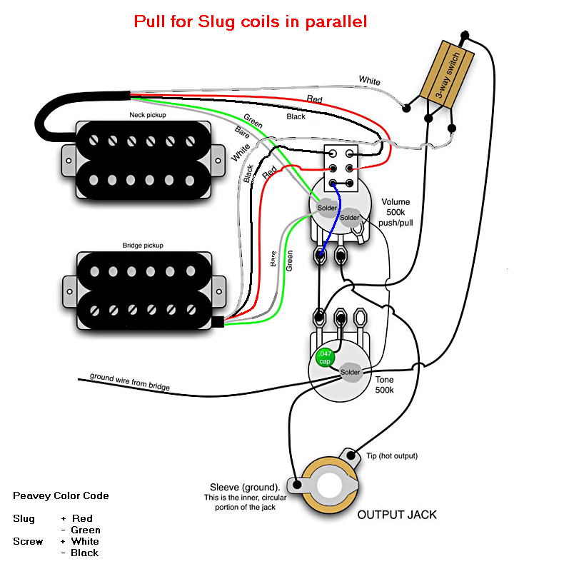 |
|
spaceangel
Rookie Solder Flinger
Posts: 10
Likes: 0
|
Post by spaceangel on Aug 29, 2012 16:08:45 GMT -5
thanks guys,will try this weekend!
|
|
spaceangel
Rookie Solder Flinger
Posts: 10
Likes: 0
|
Post by spaceangel on Aug 29, 2012 22:52:33 GMT -5
3 pole switch diagram? please and thanks!  |
|
|
|
Post by reTrEaD on Aug 30, 2012 13:30:13 GMT -5
3 pole switch diagram? please and thanks! Just take the diagram above and make a few simple alterations. 1 - The switch shown has 2 columns and 3 rows. Add another column so you'll have 3 columns and 3 rows. 2 - Break the wire that goes from the pickup selector to the left-most terminal of the tone control. 3 - Connect one loose end of the broken wire (doesn't matter which) to the terminal at the top row of the new column. 4 - Connect the other loose end of the broken wire to the terminal at the middle row of the new column. 5 - There is no five. You're done already! |
|
spaceangel
Rookie Solder Flinger
Posts: 10
Likes: 0
|
Post by spaceangel on Sept 2, 2012 20:49:52 GMT -5
if I decide Iwant hum cancelling in the inside slug coil parallel position,what are my options?Right now the adj.coil is hot[wht].I am gonna have to run 4 cond.wiring any way cause these pickups don't have it.I've already flipped the magnet on the front,but now I'm gettin confused about polarity and phase issues.Sorry to be a pest,lol
|
|
|
|
Post by reTrEaD on Sept 3, 2012 10:29:18 GMT -5
By flipping the magnet, you've reversed the phase of the output. To correct for that, you'll need to reverse the connections on EACH of the coils of the pickup with the flipped magnet. By doing that, you'll reverse the phase of the hum signals on each coil. So your slug coil on the pickup with the flipped magnet will now hum-cancel with the slug coil on the normal pickup.
Using the earlier diagram, White was the (+) on the screw coil and Black was the (-). So you would use the Black of the pickup with flipped magnet for (+) and White for the (-).
Same kind of swap on the connections from the slug coil of the pickup with the flipped magnet.
|
|
spaceangel
Rookie Solder Flinger
Posts: 10
Likes: 0
|
Post by spaceangel on Sept 4, 2012 17:16:16 GMT -5
So,if I understand correctly,on the front pickup[flipped magnet] in it's series humbucking mode:black is hot,red is ground,and white and green are the series connection?I'm not opposed to tryin things first before I ask you.It's just that I'm waiting on some 4 cond.wire and a 3pdt switch to be shipped to me.Before your last post,my thought was to get a 4pdt switch and hook everything up that we've talked about so far with this addition:
1.make geen hot and white ground on front pickup w/flipped
magnet
2.run the green to the middle lug of the 4th pole
3.one side to the 3 way switch[normal mode]
4.other side to ground[slug coil parallel mode]
any thoughts?
|
|
|
|
Post by reTrEaD on Sept 4, 2012 22:44:57 GMT -5
Space, there are a few things you'll need to keep track of when you re-cable these pickups. If I have time tomorrow, I'll make a drawing that might help.
|
|
spaceangel
Rookie Solder Flinger
Posts: 10
Likes: 0
|
Post by spaceangel on Sept 9, 2012 19:01:23 GMT -5
Ended up coming up with this,kinda half "johnh" and half "retread",It seems to work...thanks for your time and patience. Doug  0908121019a 0908121019a by twangdang, on Flickr |
|
spaceangel
Rookie Solder Flinger
Posts: 10
Likes: 0
|
Post by spaceangel on Sept 9, 2012 19:10:38 GMT -5
I call it the"Insta Cluck"switch,LOL!
|
|
|
|
Post by reTrEaD on Sept 10, 2012 6:59:05 GMT -5
Doug,
I dropped the ball here. I should have made a drawing to prepare you for what you'd find inside the HB when you opened it up. But it looks like you were able to sort things out on your own.
From the looks of the colors you chose and where you used them, you were consistent in slug v screw and start v finish. So your flipped magnet pickup has opposite polarity on the output of each coil. Then you compensated for that in the way you connected the pickups. This all makes good sense.
I'm impressed with how you managed the result. Since your flipped magnet pickup has the screw coil on the bottom of the series string, you shunted it to leave only the slug coil in the circuit. The normal magnet pickup has the slug coil at the bottom. You disconnect it at the series link and connect it directly. It all looks good on paper.
+1 for a great job of problem solving by incorporating ideas from different techniques. And for taking the time to report about the results.
|
|
spaceangel
Rookie Solder Flinger
Posts: 10
Likes: 0
|
Post by spaceangel on Sept 10, 2012 7:06:55 GMT -5
I managed to finish it before saturday's gig.It worked fine!A familiar sound,but new to this guitar.
|
|
|
|
Post by reTrEaD on Sept 10, 2012 7:12:43 GMT -5
The name "Insta Cluck", suggests that sound is similar to a strat quack, yes?
|
|
spaceangel
Rookie Solder Flinger
Posts: 10
Likes: 0
|
Post by spaceangel on Sept 10, 2012 16:39:23 GMT -5
Yes,I know that PRS does this on one of their rotary switch positions.I used to have one, so I already knew it would be a convincing "quack".The thing I like about this project is that I could get that sound for less than 20 bucks in parts while still maintaining the original control scheme if needed.Would have been nice not to have to drill a hole,but I haven't seen a 3pdt push/pull pot.I'd rather have push/push anyway....
|
|
|
|
Post by reTrEaD on Sept 10, 2012 23:10:14 GMT -5
Well you could have had a push-push 4PDT pot (Fender S1). But not for under $20. The knob alone would cost you $10.
|
|


