vhgtar00
Apprentice Shielder

Posts: 28 
Likes: 0
|
Post by vhgtar00 on Nov 11, 2014 18:13:38 GMT -5
Okay. This time, I fixed the wire colors and positions (i.e. SF = Red & SS = Green). I stuck my 4PDT coil select switch before everything, and wired the rest just like the JP Wiring Diagram (besides converting the coil split switch to a Spin-a-Split). If this looks alright, all I need to do is add in a treble bleed circuit ( Source One, Source Two) and I should be good to go. On the subject of the 4PDT switch: I still don't know how I can downgrade to 1 pole and keep the same functionality, but as long as the 4PDT works, it won't matter to me because I prematurely (and stupidly) bought the switch before I had the diagram down. Diagram Notes: A black colored wire joins the hot wires from the 4PDT switch. A pink colored wire joins the series link wires from the 4PDT switch. A cyan (read: light blue) colored wire joins the grounds from the 4PDT switch. A yellow colored wire carries the output from the Volume potentiometer to the Pickup Selector Switch.  |
|
|
|
Post by newey on Nov 11, 2014 20:22:06 GMT -5
vhg- No time at the moment to fully vet your diagram, but at a first glance, I think you've still got issues with the coil select and spin-a-split. JohnH suggested this: His idea of drawing this out in modules is a good one, it would simply both the drawing and the vetting. You don't need to go out and buy SPDT switches to do as John suggests- you can simply use one pole of the 4PDT switches you have. But costwise, I'd save those items for a future project, and go get a pair of SPDT switches, these will be quite cheap compared to the 4-banger. My take on John's suggestion is this, which is one module up to the point of the phase switch: 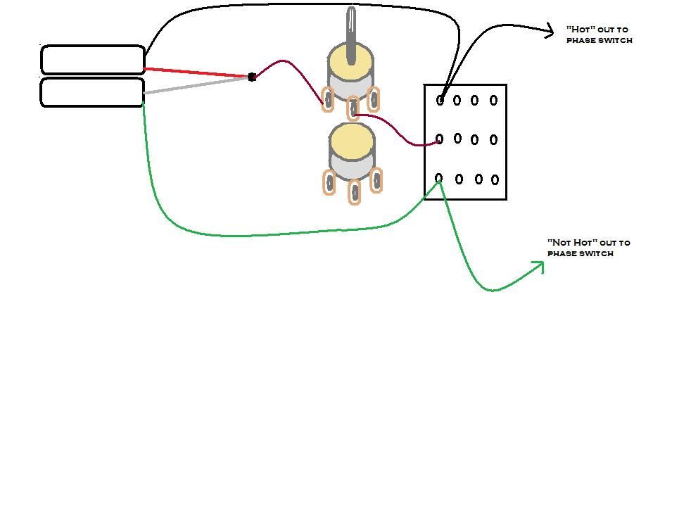 He (or someone) will need to check my work, but I think this is what he meant. |
|
|
|
Post by JohnH on Nov 11, 2014 22:03:04 GMT -5
Yes that's it..thanks newey..sorry to have been scarce recently. I can try to post a pencil sketch of the whole thing if needed..in a few days.
|
|
|
|
Post by sumgai on Nov 12, 2014 4:06:30 GMT -5
This is beginning to sound like "beat on v-day" here in the NutzHouse..... V..., Sorry, but I'm gonna limit my reply to one "finding of error" - this time it's the Bridge pup that won't be heard, unless you're in series mode. At least I see no connection between the pup and its Vol control, and thence to the pup selector switch. At this point, I'm with newey and the others - try doing just one thing at a time. IOW, simplify ! Let's run through an example, shall we? So you should have one pup, one vol control, and an output jack - that's a wrap! Now add the tone control. Still working? OK, let's try adding the spin-a-split function. Here, I'd recommend that you consider choosing a coil, and making it a permanent selection - no switch. (Or even simpler, use a switch only, no "blend" control (which is what the spin-a-split pot is, a blender).) But if you do wish to go down the road you've been on, then I gotta tell ya, you really don't need that honkin' big 4PDT to select a coil for spin-a-split, your previous version was doing that job just fine. (And yes, I know that goes against the Nutz grain, but right now, I want to stress the part about simplify.) OK, so we now have a working single pup axe, ready to Rock! It does choose-a-coil split, and it has Vol and Tone pots - cool. Let's do it again.... You now have two complete modules, and you want to hook them together. The world standard is to do it in parallel (though there are some axes out there that did it in series only), but us Nutz, we know better, don't we?  As I said before, choose now whether you want your ser/par switch to work only when the two pups are selected together, or if it should over-ride the pup selector no matter what it's set to. Think that's what you have now? No, I have to disagree. What you have now (besides the problems already mentioned) won't work quite like that. You see, if you're gonna have a blend-able combo, whether in series or parallel, then you're gonna have to disassociate the Vol pots from their normal connections, i.e. - you can't have both of them going directly to the pickup selector switch. Cement this in your head - only one of them is going to go directly to the output, and only the other one is going to connect directly to ground. The kicker here is - you need to place the pickup selector switch between the two pups, no ifs, ands or buts about it.* Or, if you really don't mind having a Master Vol pot when in series mode, then by all means, use your current system. Just be sure to find some way for the Bridge pup signal to get out, when not in series with the Neck.  vhgtar, this all isn't meant to pee in your Cheerios, it's meant to cajole you into thinking logically, in order to achieve your goals. Sure, any one of several of us could whomp up a circuit and hand it to you, but what do you learn from that? And while we sometimes do that, we find that most recipients of such largesse never return to The Nutzhouse.  I'd rather you "got used" to coming around here, and eventually started offering up your own help, to other fresh newbies. At least, that's my goal.  HTH sumgai * Spoiler alert: I already know what's gonna happen here, placing the pup selector between the pups... and I know why. This is where a design compromise is gonna take place, sorry to say. (Or, to overcome the issue, we can really go Nutz-out on the design, but that gets well away from simplicity, and increases the cost of parts... I think some of the other Nutz can see where I'm heading here.) |
|
vhgtar00
Apprentice Shielder
Posts: 28
Likes: 0
|
Post by vhgtar00 on Nov 16, 2014 23:05:55 GMT -5
Instead of Frankensteining my diagram, leading to an eventual failure within the Series/Parallel switching route like all the other diagrams, I decided to split this all up into segments and work logically:
Step 1. Signal Modification Stage Pretty much all the stuff I know how to do. This covers the master volume, coil blend volume, tone, OOP switch and the Coil Select switch (simplified thanks to JohnH). Step 2. Pickup Selection Stage Send Hots to Pickup Selector Switch. Outputs pass or ground accordingly. Step 3. Series/Parallel Stage At this point, I was a bit stuck. I tried the conventional DPDT switching method but it only works when Neck and Bridge are both going to output. I was wondering how to get around this through methods like 'checking' to see whether or not the signal is grounding at the selector switch, using a rotary switch, a relay, etc. I then realized... I have a 4PDT. Why not try and make use of that? Using the 4PDT after the Pickup Selector Switch, something is always going to the Output Jack no matter which switching route is selected. That way I don't have 'dead zones'.
I hope you guys confirm my hopes that this is in fact the diagram I was hoping to create. Fingers crossed.  |
|
|
|
Post by sumgai on Nov 17, 2014 2:24:18 GMT -5
Well, call me Groucho and sell it to me for a dollar! No, seriously, I see only one little detail that doesn't detract from the overarching fact that this thing works. The only thing that I had been harping about in terms of simplicity was the fact that not everyone has a 4PDT switch sitting in his/her spare parts box. But like I always say, if you already got it, then why not use it! So here's my fly in the ointment: take a look at the split-coil blend control... one side goes to ground right? Well, if you flip the coil-select switch to "ground", then rotating the pot will simply go between the extremes of..... ground and ground. Not much difference in tone, I'll wager. Equally, when that same switch is flipped to 'hot', then the coil-tap is going between 'hot' and ground. What's wrong with that, you ask? Well, it means that the coil-tap wiring is always going somewhere, either 'hot' or ground. The problem, at least for me, is that it never gets left alone, so that the Bridge pup can do its full Hb thing. Of course there are two solutions, but the more obvious one would be to have a SP3T that has a center off position. This is also called (quite incorrectly) by most parts suppliers as a DPDT, although they do usually put in the parens part of (on-off-on). That way you can go from full Hb to partially blended, or completely cut out, single coil tones. The other fix, and even cheaper, is to simply not connect the third lug of the pot to ground. That way, you're introducing the red/white wires to maximum resistance, and therefore they aren't really going to see either 'hot' or ground, no matter which way the switch is flipped. But when you do want that connection to be "in play", simply turning the pot all the way over will remove the resistance, and Whoala!, the Bridge pup is suddenly a single-coil puppy. And for the final portion of this thread - post soundclips, or it didn't happen! HTH sumgai |
|
vhgtar00
Apprentice Shielder
Posts: 28
Likes: 0
|
Post by vhgtar00 on Nov 22, 2014 18:15:34 GMT -5
So I put sumgai's additional tweaks into effect. A little while later, I got the last parts I needed for the project in. The problem is, the parts are overcrowding the pickguard. Due to this, I decided to simplify the circuit again and try to reuse the 5 way switch that was already in there. To make the 5 way switch act like a normal 2 input 3 way switch regardless of the wiper, I used two diodes to direct the current of both pickups into the middle slot. If I'm correct, then my selector switch works like this: N, N, N+Br, Br, Br. I also simplified the Series/Parallel switch so that I don't have to shove a 4PDT inside. No more coil select either  Let me know if I did good on both of these edits!  |
|
|
|
Post by newey on Nov 22, 2014 23:34:47 GMT -5
Everything looks good to me until we get to the 5-way switch. But then: This is simplifying things?  First off, how do you figure that those diodes are going to be tonally neutral, not "coloring" your signal in some way? Second, you don't need no stinkin' diodes . . .  The 5-way switch has 2 poles. Since you have the tone controls wired off the pickups, you're not using the second pole of the 5-way to swap between tone pots, as it is on a Strat. It's free for you to use to switch your pickups. Easy pie: 3 steps- 1) Solder a jumper between the two common lugs, and solder a wire from one common to your output +. 2) Solder the bridge + to lugs 1 and 2 on one pole of the switch. 3) Solder the neck + to lugs 2 and 3 on the other pole of the switch. This gives you N,N,N+Br,Br,Br, as you desire. If you need a reference, consult any Tele diagram, since the Tele 3-way is effectively (and electrically) the same switch. |
|
vhgtar00
Apprentice Shielder
Posts: 28
Likes: 0
|
Post by vhgtar00 on Nov 23, 2014 19:26:46 GMT -5
Okay newey, I made the tweaks. I understand exactly what you were doing and I should've done it that way too, but I had some stupid idea to keep that row open for a mod. It probably wouldn't have happened, though. I had not thought that the diodes could potentially modify the tone but it does make sense seeming as the 'black ice' overdrive mod works using a number of diodes. I've decided upon making one last modification. I purchased a set of three single coil pickups from a friend for a couple of bucks and I figured I might as well put one inside the guitar as well. To accommodate the extra pickup, I re-purposed the two non-concentric pots so they now work as the Middle Pickup Volume and Master Tone respectively. I also included a SPDT switch to Kill/Bypass the Middle Pickup. If this is all good to go, then it'll finally be time for me to whip out the soldering iron and get to work. Thanks again!  |
|
|
|
Post by newey on Nov 23, 2014 23:26:54 GMT -5
vhg- Dang, you keep moving the target!  OK, if the middle pickup is now in the game plan, things change. First of all, your 5-way switch is still Gefooey. You show both the neck and bridge pickups jumpered across all 3 lugs on one side of the switch. This means that you will have the neck and bridge pickups both on at all times, not what you want. Here's what I would suggest: You have an on/off switch for the middle pickup. Just use that switch to turn the mid on/off, and forget attaching the middle pickup to the 5-way switch entirely. Just run the mid + straight to the output. That way, you can add the mid to whatever is selected on the 5-way switch. Then, you can wire the 5-way as I suggested previously, using one pole for the neck pup and the other for the bridge. The only bit of "wonkiness" that I see is that the series setting (N * Br)operates only when the 5-way switch is set to positions 3, 4 or 5. If you can live with that, the rest of the diagram looks OK. |
|
vhgtar00
Apprentice Shielder
Posts: 28
Likes: 0
|
Post by vhgtar00 on Nov 27, 2014 16:08:52 GMT -5
The diagram is now fixed. What I did was change the Global Series/Parallel Switch back to a 4PDT. Because of this I had one DPDT still open and decided to do a Neck Local Series/Parallel option on it. I also connected the Middle Pickup directly to output after the SPDT Bypass toggle switch. I believe this will work just fine. My question with this is, can you wire Neck and Bridge in series and then select only the Neck or Bridge? If so, will it produce a different a sound than if you were to do the same thing in parallel? My thoughts are no, which is why bypassed the toggle switch on the Global Series mode to always produce N * Br, but if I'm wrong, then I might need to make an edit.  It's weird for me to say this, however, because although I'm pretty much done, I keep on thinking of better ways to improve this circuit. I feel now that I've had some experience in wiring the guitar, I want to explore more options to wire this guitar up. That's really been the theme of this whole thread. First I wanted to do some thing with 2 pickups, JP Wiring, three pots. I now have developed an HSH Configuration with 6 Pots (4 from the two concentric) and 4 switching options, and there's still more I want to do. I think it's going to take some time for me to settle on something and when I get it down, I'll make a new thread, but until then, I don't want to bother you guys with each new idea and revision I have. Cheers on a job well done! I thank you all for your support. vhgtar00 |
|
|
|
Post by newey on Nov 27, 2014 22:06:30 GMT -5
vhgtar-
I think the latest diagram traces out OK, although I'm not too sure about whether the neck series/parallel switch is playing nice with the 4P global series/parallel. Let's get another set of eyes on it.
The 4th pole of the 4PDT is superfluous- you're switching the white wire from the Br pup between ground and ground. Every extra connection is a potential failure point, so just wiring that straight to ground is simpler and saves 2 solder joints and a switch pole.
You show the 4PDT bypassing the 5-way, so no, you can't do that with this scheme. Bypassing the 5-way is the way to do this mod,IMO.
Your thoughts are correct. The sound of one of the two pickups will be the sound of that pickup.
Switching pickups in series requires (as UnclMickey once said) a bit more "housekeeping" than parallel, since the pickup to be turned off must be bypassed, end-to-end, in series, so as to not break the series "chain", thereby killing all output. (See the wiring for any "Brian May Special" to see how this is done.)
|
|
|
|
Post by sumgai on Nov 28, 2014 0:20:32 GMT -5
v'ger, newey has read my mind vis-a-vis the fourth pole switching between ground and ground - a possible failure point, to be avoided if possible. But the Neck Ser/Par switch is fine, and is playing nicely with the 4PDT "master" Ser/Par switch. However, there is yet another problem, albeit it's probably at the nuisance level, and not the "curses" level. Looking at your 'blend', what do you think will happen as you rotate the control towards ground, and the (Neck) Ser/Par switch is in parallel mode? That's right, it will now control the whole pickup's output, not just that coil, because both NS and SF are tied together, and thus both are being shunted towards ground by that control. Oh, and did I mention that this effect will cross over to the Master Ser/Par switch?  I'm sure you can work out the details, but again, this may be nothing more than a bit of a "watch out for that", not a true killer.... but that's up to you. All of this is not to say anything about how both blend controls are always applying an additional load to their respective coils, and thus to the pickups overall. Generally speaking, that's not good for the tone. Best to use the wiring you have, and find a pair of so-called "no-load" pots, to ensure that you are breaking the connection between the incoming lead and ground, when the pot is rotated fully towards the "coil is not grounded" end of things. However, a dual-concentric pot, one deck of which has a no-load option built-in, that's not gonna happen. Either you rearrange your circuitry to swap the tone controls with the blenders, or else you create your own no-load pots - ask JohnH for details on how to do this. A final point, and truly a niggling one, but I think you're gonna suffer some problems with out-of-phase tones, unless you just accidentally chose the incorrect Bridge coil leads to use for 'hot', ground and such (compared to what you chose for the Neck pup). BTW, I'm not so disturbed by newey (the moving target trick), but I do wonder.... whatever happened to the killswitch option? OK, that's it for now! sumgai |
|
|
|
Post by newey on Nov 28, 2014 9:03:45 GMT -5
If you knew me better, you might be . . .  |
|
|
|
Post by sumgai on Nov 28, 2014 12:51:50 GMT -5
Hmmmm, Looking back, I see that I didn't quite get my editing ducks all lined up... I was going to say something like "disturbed by these changes as newey", and then changed my phrasing to say "disturbed as newey by these changes", forgetting, of course, to change the preposition. But looking at the bright side of things, at least now we know a bit more about our Fearless Co-leader! |
|
vhgtar00
Apprentice Shielder
Posts: 28
Likes: 0
|
Post by vhgtar00 on Dec 1, 2014 0:32:11 GMT -5
As I say with every one of my posts... "Alright guys, this is it! The final diagram!" In all seriousness, I've decided to stop with all the fancy-schmancy wiring crap I've been trying to do with 32 potentiometers and 64 switching options. This project all started as a way to improve a faulty wiring job on a guitar but at every step it has expanded to the point where I put out a diagram and then I'd pose the question: "How can I make this simpler so I can justify cramming more switching options in here?" This would lead to another edit, another couple problems to solve and a new diagram. Not only is this bad because it takes away so much of our time as a collective whole, but it takes up all the free time I have that I would otherwise use playing said guitar. vhg- We don't delete threads around here. Someone else may always come along pursuing the same path as you have been doing, and following your train of thought may help focus their own. Another thing to keep in mind, too, is that there is a penalty to be paid for adding more pots to a design. Put too many in the circuit at the same time and the tone dulls. At the extreme end of that debate is Ashcatlt, who tends to build guitars that have no pots whatsoever. . He hates pots . . . newey has read my mind vis-a-vis the fourth pole switching between ground and ground - a possible failure point, to be avoided if possible. But the Neck Ser/Par switch is fine, and is playing nicely with the 4PDT "master" Ser/Par switch. As newey, sumgai and my father have all been telling me, all these pots and switches are increasing the number of places where the wiring can fail and dulling the tone because there's too much going on. I also don't wanna be the guy who stops between every song and solo fiddling with pots and switches to get the 'optimal tone' for the part. (I admire the thinking of Ashcatlt. Zero pots sounds like a great idea as well. I just hope he doesn't play through an amp with no pots ) What I'm proposing to do is to do is keep the stock pots for Master Volume and Tone inside the guitar and use only one of my concentric 500k pots for the Neck and Bridge Spin-a-Splits. The only two switches will be the Neck & Bridge Series/Parallel option and Middle Pickup Bypass option. Treble bleed will be added to taste. I might even invest in a S1 Switch for the Series/Parallel and use up a DPDT switch for the Middle Pickup option instead of routing the pickguard to get that stock look. I'll make that decision a little later. All of this is not to say anything about how both blend controls are always applying an additional load to their respective coils, and thus to the pickups overall. Generally speaking, that's not good for the tone. Best to use the wiring you have, and find a pair of so-called "no-load" pots, to ensure that you are breaking the connection between the incoming lead and ground, when the pot is rotated fully towards the "coil is not grounded" end of things. However, a dual-concentric pot, one deck of which has a no-load option built-in, that's not gonna happen. Either you rearrange your circuitry to swap the tone controls with the blenders, or else you create your own no-load pots - ask JohnH for details on how to do this. I have zero understanding of load. Can you describe the concept a little bit to me? Also, is there a way I can modify a pot to make it no-load, assuming I can get to the critical parts? If not, and if my tone suffers a lot, I may just resort to DPDT Coil Split instead of Spin-a-Splits (assuming that doesn't still cause the inherit load problems). Here's the diagram:  Fingers crossed! |
|
|
|
Post by sumgai on Dec 1, 2014 2:45:06 GMT -5
As newey, sumgai and my father have all been telling me.... What, me sound like someone's father? Now I know I'm old! I'll answer that second part first, 'cause it's easier... just ask JohnH, he's our resident expert on the subject. Now, about loads (puts on Professor Hat): Consider that a electrical power source, of any kind, puts out a flow of electrons. In order for there to be any real work done, there must be something that the power source feeds into - this is called the load. Whether it's a lamp bulb, a kitchen toaster, a motor, whatever... it loads the source so that we can get something done. We'll go past all the math and stuff about Ohm's Law, that's not needed at this time. What you're interested in is this: In any circuit, what goes out of the power source must be returned to it, which is the definition of a complete circuit. Since we can put multiple circuits into play, all being fed by our power source, they can be characterized as either connected in series, or connected in parallel. Here's where it gets interesting, and pertains directly to your question: If we have multiple circuits connected to the power source, it's fair to say that we have multiple loads. For our purposes here, what concerns us is the fact that a tone pot dangling off of a pickup is one such complete circuit that has a load (oooh, that pot is a resistance!), usually in parallel with the volume control (another load), and with the amplifer-and-cable (since they share a common grounding point, and need I reiterate the obvious here?). Now you start to see what we've been harping about - the more pots in a circuit (connected in parallel), the more loading going on. Without all the hubbub, take it as an article of faith (for now) that the greater the load, the more harm to one's tone. That's it in a nutshell. If I go any further, we're gonna have to go all math-y and stuff, and you don't wanna see me do that, do ya? Any further questions, just ask! sumgai |
|
|
|
Post by newey on Dec 1, 2014 6:58:00 GMT -5
sg and I both tell you to ask JohnH, which is our way of saying we can't find the thread he wrote on the subject. It probably should have been "stickied" in the Reference section, but wasn't.
I don't know that John has tried the mod on a dual-gang pot, but the principle is the same. You disassemble the pot and scrape off the resistive track (both tracks, for a dually) at the "10" end of the rotation. John claims to have a 100% success rate at doing this, having never wrecked a pot in the process. I've not personally tried this.
Switches don't add to the load like a pot does. The load caused by a pot is due to the resistance of the pot; a (properly wired) switch should show 0Ω resistance across its contacts (there is some resistance there, to be sure, but it's less than a multimeter will detect and won't affect anything).
Here, you've tapped into a common theme around here, namely whether it is better to have a guitar that "does it all", so to speak, or one that has fewer tone choices, but with easier access to those tones- less fiddling around. The "all-everything" guitar is fun to do as an exercise, and may be useful in a studio setting where "switching on the fly" isn't so critical. But for live use, simply is generally better.
If you want to be able to quickly select a split coil option, a switch is quicker and surer. Of course, you lose the nuances- a little of one coil with a lot of the other. But not only is it trickier to "dial in" the spin-a-split, you can also easily dial it out while playing vigorously, if you brush the pot. These are all things to think about if a gig-worthy instrument is the goal here.
Your latest diagram looks fine. While it will work as intended, consider swapping the wiring around on your volume control (IOW, the center wiper connection goes to output, the input goes to the left-hand lug). It will work as shown, but the guitar won't be "off" at "0" on the volume. The way you show it is appropriate for individual volume controls like on an LP, but a master volume is usually wired as I describe.
|
|
|
|
Post by reTrEaD on Dec 1, 2014 8:12:57 GMT -5
we can't find the thread he wrote on the subject. This is similar: John made a no-load blender in this thread. In that case the scraped section was in the middle of the rotation instead of at the end. But it does include a pic. |
|
|
|
Post by JohnH on Dec 1, 2014 14:27:54 GMT -5
Hello, I think you guys have arrived at a good design. I would not worry about the loading caused by those spin-a split controls, since they are only affecting half of each pickup, ie one coil. In this case, I had exactly that, using a no load pot and although in theory there is something to be had when it goes to fully off, in practice, I cannot hear it. This includes my LP and my Strat. The strat has a 8.4k humbucker, with a 250k no load pot doing the humbucker/single transition. It is no load, but I don't get anything audibly extra at the click. Log taper pots are best if possible, so you get plenty of control as you move from fully single, to adding a bit of the other coil and there are some very nice extra sounds there.
No load pots seem to be most important when they are taking load off the whole system from hot to ground, like in a tone pot (you might consider that instead), also in the normal simple parallel blender that people do on Strats, to mix B with N.
No-loading a pot is quite simple, if it is a full sized single pot, its easy to take the back off, get th etrack out and scratch it carefully, testing with a meter. Double pots are much trickier. the one that ReTread pointed to is the only type that I have done. All the others that I've seen have been mechanically too locked together to get the back off without wrecking it. But, Greekdude did achieve this in one of his threads a few months ago.
J
btw - Ive found this thread difficult to follow due to the attached images, since nearly all my GNut time is on my phone, and getting images and seeing them is very awkward. Its much easier with images in the thread posted with IMG links.
|
|
|
|
Post by JohnH on Dec 1, 2014 15:17:28 GMT -5
Spoke too soon!
On the neck pickup, instead of taking the right lug of the spinasplit to ground, take it to the pickup green wire. Then, when in series mode snd neck is on the hot side, you can still split it without losing all thd bridge sound too
|
|
vhgtar00
Apprentice Shielder
Posts: 28
Likes: 0
|
Post by vhgtar00 on Dec 9, 2014 17:38:59 GMT -5
Okay guys, it's work time. I got all the parts and my friends at the school Machine Shop drilled the holes for my pickguard. One question before I wire it up, though.
I was recommended not to put in the old 250k pots because they aren't the best of quality. Given this, I've decided to wire in a Series/Parallel option for both local Humbuckers. As long as I do this before the wires go to the volume (I know Blending coil positive must go to blend before this switch), will this change anything in my diagram?
Looking forward to getting this guitar finished. Will include pics, sound-bytes.
vhgtar00
|
|
vhgtar00
Apprentice Shielder
Posts: 28
Likes: 0
|
Post by vhgtar00 on Dec 9, 2014 21:23:26 GMT -5
Wow... one more thing. I just got back from my local music store (because screw Guitar Center) and picked up a real score piece. It's a Dimarzio stacked humbucking single coil pickup... only $10 like new!
I know that I can wire a switch to get this thing between tapped settings. How would I do such a thing? (I tried finding a resource but the misinformed split is a tap drawings are all I get and DiMarzio's website is very unorganized).
I got Red, White, Green, Black and Bare wires coming from the pickup. Bare to ground.
For a humbucker pickup (not stacked, but could be the same for what I know):
Red = North Start
Silver = North Finish
Green = South Finish
Black = South Start
With that, I guess Red to absolute hot signal, Black to absolute ground. Would I then use a switch to divert Silver and Green to ground/not? Is this right?
|
|
|
|
Post by sumgai on Dec 9, 2014 22:00:22 GMT -5
v, The problem here is, we "split" or "tap" a humbucker pickup in hopes of obtaining different sounds. That comes from the fact that the magnets-and-coils are in different positions along the length of the string. A single-coil sized Hb has no such distinction, both coils/magnets are in the same position along that length of string. Granted, by selecting one coil, you change the overall inductance of the pickup, and that will have an effect on the tone, but trust me, it won't be noticible to anyone except you.... and that, only in a very quiet environment - certainly not on stage at your local pub, that's for sure. My advice at this point would be, try it in the Middle position as a full Hb only. If it sounds good by itself (and quiet!), and in combination with the others, then use it in this axe. But if it doesn't sound any better than your current Mid pup, then set it aside. For that price, you got a good deal, so don't be afraid to save it for your next project axe. HTH sumgai |
|
vhgtar00
Apprentice Shielder
Posts: 28
Likes: 0
|
Post by vhgtar00 on Dec 9, 2014 23:38:27 GMT -5
I agree that in conjunction with one or two extra humbuckers, toggling the middle pickup's coil tap will probably not result in much of a change in tone, but I'm sure that by itself or with another single coil it would. When I realized that it was probably better to use the Push/Pull pots instead of the stock pots, I went back to my crazy schemes one last time. I came out with 4 switching options I think I'd really like. - Global Series/Parallel (Toggles between N + Br, N * Br)
- Dual Local Series/Parallel (Toggles both Humbuckers between Series and Parallel with themselves) (I really have come to enjoy the sound of that Parallel tone)
- Coil Tap Toggle Switch (Toggles between the tapped settings of the Middle Pickup)
- Middle Setting Selector (Description below)
Okay, so with this middle pickup, I wanted to get back to the Fender Style 5 Way Setting, yet still be able to get those Gibson Neck and Bridge Pairs, so I came up with the idea with the Middle Selecting Selector switch. What it allows me to do is switch what pickup settings go to the middle pickup position on the selector switch. Selector set to Middle: ( N, N + Mid, Mid, Mid + Br, Br ) // Standard Fender Selector Settings Selector set to Humbuckers (N + Br): ( N, N + Br, N + Br, N + Br, Br) // A redundant style of the standard Gibson Selector Settings Now I've been wrong many times before when I've said this, but if the diagram seems all up to spec. then I don't see myself changing anything around anymore. I've spent enough time on the diagrams and I believe this is versatile enough for me to never ever have to change ever again. I'm very sorry for the clutterful diagram I'm posting. It literally looks like spaghetti. By the next time I post a diagram, I will try to come up with a solution to stop crossing wires everywhere in the drawing. I am a bit iffy on the spin-a-splits, especially on the Neck. I don't think that anything else should be a problem. I hope to dear god it isn't.  vhgtar00 |
|
|
|
Post by newey on Dec 10, 2014 5:42:43 GMT -5
vhg-
Your diagram looks OK from a quick glance (on my way out to work, so no time for a thorough vetting . . ).
However, your volume pot wiring is incorrect. You show the 5-way connected directly to output and two lugs of the V pot are shown as grounded.
To fix it, the input from the 5-way switch goes to the left hand lug. Center (wiper) lug goes to output. Third lug is grounded.
Also (just a matter of simplifying things), since you aren't using the second pole of the 5-way, there is no need to jumper the two halves of the switch together, just run directly from the one commons to the V pot. This eliminates two unneeded solder connections.
|
|
|
|
Post by sumgai on Dec 10, 2014 18:11:14 GMT -5
v, I think there are couple of quirks, but by and large, it'll do what you want. The first quirk (and not a gotcha, just a quirk) is that the Mid on/off switch is gonna make the 5-way redundant when set to off - it ties together both Neck and Bridge pups, thus all 5 positions will have the same output tonality. Wiring for that effect can be simplified, to say the least, but that's probably not what you wanted. This can be cured, I'll let you figure it out, but here's a clue: use that second, unused pole of the 5-way to interrupt either the Neck or the Bridge 'hot' lead, as appropriate. The other quirk I found is that the Ser/Par switch will not completely override the 5-way. If you have the Mid on/off set to on, and the 5-way in either positions 2, 3, or 4, the middle will still be audible at the output - it'll be in parallel with the other two, giving the combo (N * B) + M (In positions 1 & 5, the Mid won't be audible.) Again, I think this can be fixed via the unused pole of the 5-way, but I haven't thoroughly gone through it yet to double-check my suspicions - that part is also up to you. Good luck! sumgai |
|
vhgtar00
Apprentice Shielder
Posts: 28
Likes: 0
|
Post by vhgtar00 on Dec 11, 2014 12:00:41 GMT -5
v, I think there are couple of quirks, but by and large, it'll do what you want. The first quirk (and not a gotcha, just a quirk) is that the Mid on/off switch is gonna make the 5-way redundant when set to off - it ties together both Neck and Bridge pups, thus all 5 positions will have the same output tonality. Wiring for that effect can be simplified, to say the least, but that's probably not what you wanted. This can be cured, I'll let you figure it out, but here's a clue: use that second, unused pole of the 5-way to interrupt either the Neck or the Bridge 'hot' lead, as appropriate. The other quirk I found is that the Ser/Par switch will not completely override the 5-way. If you have the Mid on/off set to on, and the 5-way in either positions 2, 3, or 4, the middle will still be audible at the output - it'll be in parallel with the other two, giving the combo (N * B) + M (In positions 1 & 5, the Mid won't be audible.) Again, I think this can be fixed via the unused pole of the 5-way, but I haven't thoroughly gone through it yet to double-check my suspicions - that part is also up to you. Good luck! sumgai Quirk #1: I just fixed that on paper. I'll have a diagram complete when I get back to my normal computer. Quirk #2: I noticed that around the time of the post and it doesn't bother me that much. I think it's a little bit interesting and it doesn't cause any problems so it's a keeper |
|
vhgtar00
Apprentice Shielder
Posts: 28
Likes: 0
|
Post by vhgtar00 on Dec 11, 2014 18:13:47 GMT -5
Diagram finished. Tried to make it a bit easier on the eyes.  |
|
|
|
Post by ashcatlt on Dec 11, 2014 20:34:33 GMT -5
I don't have anything real to add to this thread, but I'm bored* at work, so... I don't know that John has tried the mod on a dual-gang pot, but the principle is the same. You disassemble the pot and scrape off the resistive track (both tracks, for a dually) at the "10" end of the rotation. John claims to have a 100% success rate at doing this, having never wrecked a pot in the process. I've not personally tried this. I have never done this with a dual pot, but with singles, I never actually remove the wafer, just pop the back off and do the cut. And I do mean cut. Never bothered scraping anything. Just take a nice sharp xacto or something, a little firm pressure, and a good quick whack and it's done. Never had a problem. I don't love this. 0Ω is actually an infinite load. The important point in this case is that in the other position, there is (effectively) infinite resistance between the contacts, which is the same as saying infinitely small load. That is "load" and "resistance" are inversely proportional - a lower resistance demands more current from the source, and thus is a heavier load. Having fun yet? My main live guitar is HHH, with both local and system-wide series/parallel/split options. I haven't bothered to count up all the options, but it's just absurd. I only rarely use any of those options in a live setting. I usually set it to either the Middle pickup or some combination of Bridge and Neck. Every once in a while maybe I'll flip the system S/P switch, or put the Neck OOP for something special, but I have a real hard time keeping track of those things in the heat of the moment. I use my right hand ("picking technique") to make the more subtle adjustments to volume and tone, and my feet (stompboxes) for more drastic changes. All the fancy switching options can be nice for recording, but really aren't as important as you might think for a live performance. Of course, I'm not in a cover band trying to emulate the sounds of your favorite albums. If that were the case, I'd probably go to a Roland VG system so I could switch quick with my feet or even sequence up the changes via MIDI control. *I hate that word "bored". I always tell people "Only boring people get bored", and I really never am. I'm perfectly capable of amusing myself any time of the day or night no matter the situation. I used the term here because it felt like the easiest way to describe the situation. My job is almost 100% customer driven. Until the phone rings, I have absolutely no duties other than to sit in my seat and be prepared for the phone to ring. In between, I do a lot of surfing... |
|


 I'd rather you "got used" to coming around here, and eventually started offering up your own help, to other fresh newbies. At least, that's my goal.


 I'm sure you can work out the details, but again, this may be nothing more than a bit of a "watch out for that", not a true killer.... but that's up to you.


