|
|
Post by robbertmerrett on Oct 23, 2015 15:53:52 GMT -5
I've bought a hotrail (Seymour Duncan) pick up. And want it in my telecaster deluxe but it has a s1 switch that makes the neck pick up and the bridge pick up a humbucker when pressed. I want the s1 switch to work as a push/pull coil tap for only my bridge hotrail as I'm keeping the n3 neck pick up in there but don't want it to run off the s1 switch can anyone help with a wiring diagram "hand drawn" or anything? Please I need this guitar ready to gig  Thanks |
|
ubertech
Meter Reader 1st Class

Posts: 65 
Likes: 0
|
Post by ubertech on Oct 24, 2015 1:58:00 GMT -5
Hi Robert, and welcome to the site the guys on here come highly recommended. I saw you on facebook and pointed you in this direction, so I probably wont be able to help you further than I did there, but I think it would really help everyone understand whats going on if you draw up a schematic of what is already there in your guitar and post it on here - just a simple Paint, or Paintbox sketch; try and be accurate with the colours to. In the past when I have been stuck, this has been needed to begin solving the problem. Include the rotary 4 pole switch you described on facebook too. thanks UT Also I suspect admin will move this to 'Guitar wiring' as this thread is for completed schematics  |
|
|
|
Post by robbertmerrett on Oct 24, 2015 2:36:04 GMT -5
|
|
ubertech
Meter Reader 1st Class
Posts: 65
Likes: 0
|
Post by ubertech on Oct 24, 2015 13:22:46 GMT -5
Hi Robert I dont have an answer for you, but I am just posting this to demonstrate how the s1 switch works, which will no doubt help which ever of the many geniuses pick up your thread later (theyre mostly on American time btw).   Looking at the switch, the left hand side 'lugs' are not being used on the fender diagram (I am labelling them 10, 11 & 12 for this - top to bottom, though on the colour diagram above, my '11' is labelled as 'common 4' ). I suspect the easy answer would be to connect: - the red and white of the new humbucker to 11
- a signal ground to 12
- The hot (green) lead from the humbucker would go to the standard switch to select it the rear position (replacing the existing hot for the bridge single coil)
BUT I am only speculating and I dont have any where near the knowledge of these guys - you are definitely in the right place to get an answer if there is one Good luck |
|
|
|
Post by ashcatlt on Oct 24, 2015 19:56:12 GMT -5
The S1 is a 4PDT switch. All you need for the coil cut is an SPST, so you'll be wasting a whole buttload of lugs. That's considered a horrible faux pas around these parts, but I'm not going to tell anybody.  Really, this is going to be a basic Tele scheme with a coil cut. Both of those exist in pictures all over the Internet (and here), so find your favorites and hack them together. Post a picture of what you think you need to do and we'll laugh at help you correct it if necessary. |
|
|
|
Post by newey on Oct 24, 2015 21:43:33 GMT -5
rm-
Hello and Welcome to G-Nutz2!And yes, I had to move your thread to Guitar Wiring. ashcatlt is right, the S-1 switch is huge overkill for just cutting one HB to SC. Buy a Push/Pull pot, or even a Push/Push if that's more to your liking. Then save the S-1 for another project, or stick it on EBay, you'll easily cover the costs of buying several Push/Pull pots. But if you must do it: 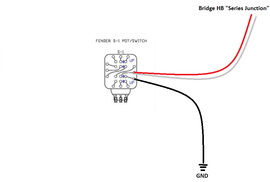 BTW, those are SD colors, so it should correspond to your new pickup. |
|
ubertech
Meter Reader 1st Class
Posts: 65
Likes: 0
|
Post by ubertech on Oct 25, 2015 2:42:22 GMT -5
The S1 is a 4PDT switch. All you need for the coil cut is an SPST, so you'll be wasting a whole buttload of lugs. That's considered a horrible faux pas around these parts, but I'm not going to tell anybody. Really, this is going to be a basic Tele scheme with a coil cut. Both of those exist in pictures all over the Internet (and here), so find your favorites and hack them together. Post a picture of what you think you need to do and we'll laugh at help you correct it if necessary. jumping in at the defence here... I think robert is keeping the original scheme as shown in his diagram, thus using up the other 9 lugs too I dont think the s1 is a retrofit just for the coil tap I like Neweys answer best cause it sounds like my guess and my guess was good (this time)  |
|
|
|
Post by newey on Oct 25, 2015 6:49:05 GMT -5
I assumed the opposite, based upon rm's first post:
My diagram assumed the S-1 was otherwise disconnected, and that the neck pickup would be wired directly to the pickup selector as per std. Tele practice.
|
|
|
|
Post by ashcatlt on Oct 25, 2015 9:01:18 GMT -5
Well, luckily the standard wiring leaves a whole section of the switch empty. If we just want to make the bridge autosplit when it goes into system series, then take what newey drew and mirror it over to that empty section. I think the black wire in newey's drawing will still want to be on the lower of the three lugs, but if that causes it to split in the parallel mode, just move it to the top lug.
If that ends up not being humcancelling (you've got 50/50 chance), then we can use the hot wire from the bridge pickup where newey has that black wire instead.
|
|


