t24
Rookie Solder Flinger

Posts: 11 
Likes: 0
|
Post by t24 on May 23, 2016 6:25:24 GMT -5
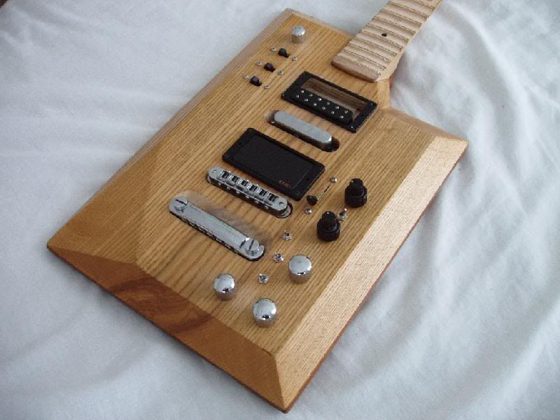
Hey guys, I'm still new at this superswitch thing and was wondering if it's possible to wire a guitar like as below (pic). And if yes can someone help me create a diagram please. Parts: Double wafer superswitch Push Pull pot
500k pot
normal output jack  |
|
|
|
Post by reTrEaD on May 23, 2016 8:35:39 GMT -5
Your map doesn't specify what connections you'll have in term of series or parallel.
The right side seems *fairly* obvious. I would guess you're trying to replicate SSS strat sound so I would *guess* that all combinations would be in parallel. But that's still a guess on my part.
The left side is even more ambiguous. Likely the #3 position has the two HBs with their coils locally in series but the two pickups are in parallel with each other in a global sense. Is that what you mean?
I would also guess that in the #1 and #5 positions, the coils are in series. This is standard for a HB. But again a guess as to what you're intending.
What happens in the #2 and #4 positions on the left side? Are the coils in series or parallel.
In any case, it looks at first glance that a push-pull pot won't do enough to get you where you want to go. But I could be wrong.
|
|
|
|
Post by newey on May 23, 2016 10:09:18 GMT -5
t24-
Hello and Welcome to G-Nutz2!
Assuming (as RT points out) that the N and B HBs are connected in series when shown as having both coils operating, and assuming further that all inter-pickup combos are in parallel, then I think this can be done with a SS plus one P/P. But I'm just spitballin' this, we'll have to get down to an actual diagram to be sure it will work.
My thought is that "mode A" (left side of the diagram), with the 2 HBs but with coil cuts when in positions 2 and 4, will require 2 poles of the SS (one pole selects among the 3 pickups and the second pole selects the single coils at 2 and 4). Pulling the P/P pot would then select "mode B", in which one pole of the P/P switches the coil cuts to the opposite coils, using the third pole of the SS, and the other pole of the P/P selects the 4th pole of the SS to give the middle pup in position 3 instead of the HBs.
Again, just thinking out loud here.
|
|
|
|
Post by sumgai on May 23, 2016 15:03:33 GMT -5
t,
Sad it is I am to have to say, you won't get what you're wanting with the parts you've got. In point of fact, you won't get that setup even with two p/p controls. But there is a solution, so hang on...
In essence, I'm going to go for each pickup combo being in global parallel, and the two coils within each humbucker will be in series (that's what we call "local series", which is standard for 99% of all stock humbuckers). That said, the situation is worse than stated by newey above. Not only do you want to go from Hb to single-coil, in positions 2 & 4 you actually want to select the opposing coils of the two Hbs. Sorry, ain't gonna happen with only two poles of a switch (as in, any standard p/p control). In fact, you need more than 4 poles, you need 6 poles to obtain your desired results. That is, to switch coils for each pup, and to select M versus B combined with N.
Fortunately for you, you can mount a 6P2T rotary switch, with an appropriate knob to make things operate in whatever way your hand wants to "flick the switch". But as pointed out by 'TrEaD, that does not get you anywhere near to any "global series" connections. Should you want any such, then I'm afraid that we're gonna have to get really Nutzy on you, and whomp up something approaching a parts count that would make CheshireCat envious. Sorta like this:
The answer to the global series part is up to you, of course, but we like to make sure that we don't have to go back to it all over again, if we can help it.... thus the suggestions/questions.
HTH
sumgai
|
|
|
|
Post by JohnH on May 23, 2016 17:19:43 GMT -5
I agree with sumgai about how to do what you showed.
An alternative suggestion would be to make sure that you really want those particular variations at positions 2 and 4, in which M gets combined with either single humbucker coil. A slight difference could resolve many of the wiring problems.
At each position 2 or 4 as shown, one option will sound a bit different and probably be slightly preferable to the other, and one option will hum while the other wont.
You could determine which will be sounding best in terms of the humbucker coil position, then spin the humbuckers so that best sounding pair is also hum cancelling (ie it has a north and a south coil)
Then, instead of having two combos of split Hb and M (one if which will hum), you have one such optimised setting at each of 2 and 4, and one with full Hb and M. That is another good sound in itself and is reduced hum.
Now that takes pressure off the second switch. In positions 1,2,4 and 5, the only changes required would be the splitting of both humbuckers. Two switch poles could do that. Then, to get your selections in position 3, two more poles is probably enough. So a 4 pole switch instead of 6 poles. That gives more options for switch type, including a mini-toggle, or the slightly pricy but very neat Fender S1 switch as used on American Deluxe models.
|
|
t24
Rookie Solder Flinger
Posts: 11
Likes: 0
|
Post by t24 on May 25, 2016 4:22:47 GMT -5
Thank you all very much for you replies.
Im sorry that I forgot to state that they would be in parallel.
I did not know that this was not really possible, as I'm still new at this.
I guess I'll just go with a different wiring since to make this possible is quite complicated.
Again thanks again for the feedback
|
|
|
|
Post by newey on May 25, 2016 6:29:59 GMT -5
Well, if both sg and JohnH say this won't work, then I guess I must be "seeing" this wrongly. So, while t24 seems to have moved on, I'd like to know here I went astray here: 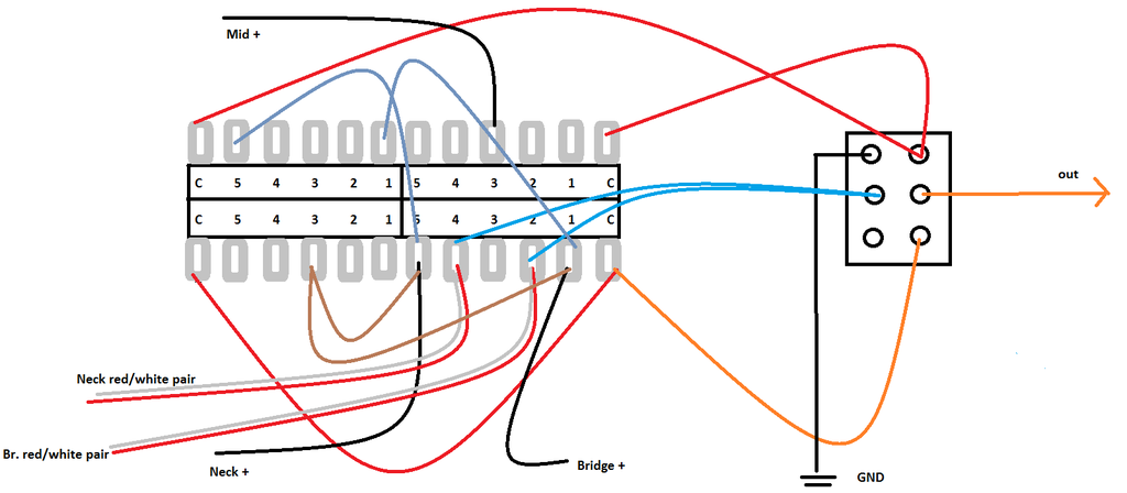 However, I agree with John as to the issue of hum-cancelling, this could be better refined on that score. But if t24 really wants to do exactly as he originally proposed, why won't this work? |
|
|
|
Post by sumgai on May 25, 2016 11:13:42 GMT -5
.... But if t24 really wants to do exactly as he originally proposed, why won't this work? Assignment of Error Number 1, Counselor: Both B+ and N+ are tied together at all times. As the return connections for these two pickups are assumed to be grounded at all times (implied in any all-parallel scheme), the required truth table is invalidated right at the outset. Further investigation for errors is moot.  The Court must reject this submission, however, leave is granted to file an amended Response.  sumgai |
|
|
|
Post by JohnH on May 25, 2016 16:28:23 GMT -5
....plus both red/white pairs from B and N are permanently joined. You'd have to love those BN combos!
|
|
|
|
Post by JohnH on May 25, 2016 17:47:32 GMT -5
Further on this, I'm handing out the following as a class exercise:
Achieve the original diagram as closely as possible using a 4-pole 5-way superswitch and a 4-pole 2-way switch.
Hint: Acceptable revisions to the design brief include transposing the selections for positions 2 and 4 on the left diagram, with those on the right.
|
|
|
|
Post by newey on May 25, 2016 20:58:22 GMT -5
Yeah, I posted this on my way out the door to work this morning (which involved a 3-hour drive from Cleveland to Dayton, Ohio). As I hurtled down the freeway, I thought about this and realized I was wrong on the series junction. But I still think this can be done- back to the drawing board!
|
|
|
|
Post by reTrEaD on May 26, 2016 8:54:59 GMT -5
Further on this, I'm handing out the following as a class exercise: Achieve the original diagram as closely as possible using a 4-pole 5-way superswitch and a 4-pole 2-way switch. Hint: Acceptable revisions to the design brief include transposing the selections for positions 2 and 4 on the left diagram, with those on the right. Two questions: 1 - Are the combinations for positions 2 and 4 on the left side of the map in parallel? 2 - Are hanging from hot issues in the 2 and 4 positions on the left side of the map acceptable. If yes to both questions, getting exactly what's in the original map is dead easy. |
|
|
|
Post by JohnH on May 26, 2016 16:03:58 GMT -5
I was assuming that all the position 2 and 4 combos would be parallel.
With regard to 'hanging from hot', while the School may occasionally accept such undesirable approaches in assignment submissions for Guitar Wiring 101, it is the agreed Academic Policy of the School to discourage such subversive circuit methodology on the Masters program. Applications for Special Consideration should be submitted to the Director of Studies on the specified form, supported by Certification from a registered Medical Practitioner.
|
|
|
|
Post by sumgai on May 26, 2016 23:06:20 GMT -5
John, ..... Acceptable revisions to the design brief include transposing the selections for positions 2 and 4 on the left diagram, with those on the right. I'm not so sure that this will accomplish anything, switching-wise. I can definitely see that one should first do a "test hook-up" to make sure that the correct coil will be selected for humbucking operation, but after that, it doesn't matter which coil (N or S) is selected during the "single coil" mode, and which is selected during the "humbucker" mode - one of them is going to hum, and the other one will be acceptably quiet. More on this, as I speak to t24, below.
That said, I now see how everything can be done with only 4 poles, instead of my earlier supposition of needing 5 poles (of a common and easily found 6P) rotary switch. A "stealthy" S1 switch would be ideal here. 
t24,
As things stand now, there are really only 8 different tonal possibilities that will be acceptable, the remaining two will hum. Eliminating the "choose the opposite coil" from the two modes has an advantage: since the sonic difference between either N or B coil (of an Hb) in parallel with a Middle pup is close to nil, you can choose just the one that doesn't hum, and thus simplify your wiring scheme. Redundancy is not our favorite word here in The NutzHouse, but sometimes we have to compromise. 
There is one caveat, however.... consider your diagram: call the Hb coils "inner" and "outer", meaning how physically close they are to the M pickup. Ideally you want the outer coils active when selected in single-coil-mode. If they hum when combined with the M pup, the cure is simple: merely swap the wires on the M pup, such that what was going to ground now goes to the switching circuit, and that former "hot" wire now goes to ground, and all will be well.
HTH
sumgai
p.s. John, if t24 still wants all 10 combos, then a 6P (rotary or otherwise) will suffice to reverse the Mid pup's phase, thus quashing my concerns. More expensive, and more room for error, but if that's what the customer wants..... |
|
|
|
Post by JohnH on May 27, 2016 3:02:10 GMT -5
Fundamentally, if you have two coils of the same magnetic polarity, and you want them in-phase tonally, then they will hum. Swapping wires can cure the hum, but it will then be out of phase and sound thin. There is only one coil of a humbucker that can be combined with a given single to make an in-phase hum-cancelling combo.
The left to right swapping in my suggestion helps so that in the right set, the humbuckers do not need to change which single coils are selected from 1 to 2, or from 4 to 5. This simplifies the switching required.
|
|
|
|
Post by gumbo on May 27, 2016 6:14:43 GMT -5
Fundamentally, if you have two coils of the same magnetic polarity, and you want them in-phase tonally, then they will hum. Swapping wires can cure the hum, but it will then be out of phase and sound thin. There is only one coil of a humbucker that can be combined with a given single to make an in-phase hum-cancelling combo. The left to right swapping in my suggestion helps so that in the right set, the humbuckers do not need to change which single coils are selected from 1 to 2, or from 4 to 5. This simplifies the switching required. ...Hey! I think I actually understand that!!!!! (almost-less g)-f-b  |
|
t24
Rookie Solder Flinger
Posts: 11
Likes: 0
|
Post by t24 on May 27, 2016 9:22:57 GMT -5
t24,
As things stand now, there are really only 8 different tonal possibilities that will be acceptable, the remaining two will hum. Eliminating the "choose the opposite coil" from the two modes has an advantage: since the sonic difference between either N or B coil (of an Hb) in parallel with a Middle pup is close to nil, you can choose just the one that doesn't hum, and thus simplify your wiring scheme. Redundancy is not our favorite word here in The NutzHouse, but sometimes we have to compromise.
There is one caveat, however.... consider your diagram: call the Hb coils "inner" and "outer", meaning how physically close they are to the M pickup. Ideally you want the outer coils active when selected in single-coil-mode. If they hum when combined with the M pup, the cure is simple: merely swap the wires on the M pup, such that what was going to ground now goes to the switching circuit, and that former "hot" wire now goes to ground, and all will be well.
HTH
Honestly I do not mind the hum. I can play around with pickups and angles could reduce it. I'm sure a little bit of hum wont really bother me |
|
|
|
Post by newey on May 27, 2016 12:52:35 GMT -5
John's point is that you can avoid the hum, and sound-wise, it really won't matter which HB coil is split with the middle. As noted, to do exactly what you wanted originally will require a 4-pole switch (despite my initial optimism that it could be done with just a p/p). So, we're back to the question of what you want to do. If you want what you originally proposed, you'll need more switching capability; if you're willing to forgo some of the combinations, thing can be simplified a great deal.
For example, if the coils being split from the HBs can be the same ones for both "modes", then this probably can be done with a P/P plus the Superswitch.
|
|
t24
Rookie Solder Flinger
Posts: 11
Likes: 0
|
Post by t24 on May 27, 2016 13:41:41 GMT -5
newey, at first I was inspired by Tosin Abasi's pickup selection(image below), but then I also wanted to be able to use the single coil in coil split mode. And that made me think why not go all the way, if possible, and make all the positions unique. So I would actually be quite happy if the middle position (coil tapped) is just the single coil alone. 2 and 4 doesn't have to be anything different if it can't be done. (Assuming all is in series mode)  |
|
|
|
Post by sumgai on May 27, 2016 23:12:26 GMT -5
guys,
I'm currently in "crisis" mode here at the ol' homestead, I have to do some deep legal research for my Home Owner's Association, we're facing some serious problems. So I'll be brief, and get back to this in more depth, later.
John, I agree that as I described it, things would go to an OoP sound, and I didn't mean for that to happen. While dreaming this up, I originally thought to simply invert the pickup, and then swap the wires around. In hindsight, this would still only eliminate hum in one combo set, the other Hb coil will still hum, without the given 5th and 6th poles... all of which does nothing to alleviate the OoP problem. Sigh. More drugs needed, no doubt. [facepalm]
t24, you say you can live with hum, and I'm fine with that - some of us can, and others of us can't. We Nutz try to work to your goals, whenever possible, and are not here to pass judgment on anyone's choices.
I note the differences between your initial diagrams, and the most recent ones. In point of fact, the most recent ones will be easy to implement, with one slight change. Given that you want to, once again, "flip the coils" such the inner one is active in position 1 (and 3), and the outer one is active in position 2, that can't be done (with your current components). Better tone, and coincidentally easy implementation, would come about if we just use the same outer coil in all three positions. At that point our DPDT p/p switch can now do what we want - split the humbucker. (The same applies for positions 3, 4 & 5, of course.)
All this is provided of course that we're still talking global parallel. Your post just above does mention "series". How should we figure that into your prospective wiring setup?
sumgai
|
|
t24
Rookie Solder Flinger
Posts: 11
Likes: 0
|
Post by t24 on May 28, 2016 10:34:21 GMT -5
Hi sumgai, So what components are needed to achieve this setup?  And sorry. I wanted to say that it will be in parallel. Not series. Thanks |
|
|
|
Post by sumgai on May 28, 2016 13:37:50 GMT -5
t,
Here's your problem: essentially, in order to "tap" or "split" an Hb, we short (or shunt, if you're in a British frame of mind) one of the coils. So let us consider first the problem of "Coil Tap Off", in position 2;
We can use one of the 4 poles of the 5-way superswitch to shunt the inner coil, no problem. Doing this will affect only position 2, none of the others. Fine so far.
Now let us look at "Coil Tap On", which shorts the outer coil. In position 2, we now see the inner coil being shorted by the 5-way, and the outer coil being shorted by the Coil Tap switch, so position 2 can't combine Nouter + M. Position 1 would be correct, but not position 2. To my way of thinking (although there's a viable chance I could be incorrect), we can't make the coil tap switch override the 5-way, nor can we go the other way around. To do so would require 3 of the 4 poles on the 5-way, and that would mean we can't select the other two pups individually. Note that this problem does not occur in positions 4 and 5 - there, the inner coil is selected for both positions. Would that we could change the requirements for positions 1 & 2 to match - things would be so much simpler!
I think that the best solution in terms of parts count and ease of use would be to use a 3-way (on-off-on) toggle switch in place of the 2-way (on-on) switch. It's not as easy to operate, but it will give you full Hb in the center, and short/shunt the desired coil when moved to either side. In this manner, you could select the best sounding (or least humming) combination across any 5-way position. (For purchasing purposes, this would be a on-off-on switch. Do not get an on-on-on switch.)
Your remaining desire, to select either M or N + B, really should be a separate part, if for no other reason than ease of use. However, that said, a 4P3T switch is not prohibitively expensive, and it would give you the ability to split the Hbs in position 3, Nouter + Bouter. That might be of use to you, I dunno.
All in all, the problem you pose is not impossible to solve, but the solution requires something more than common parts. I'm not insisting that you change the desired coil split in positions 1 & 2, that's up to you - but doing so would make this exercise a lot more simple, and dirt cheap for you to implement.
Your call.
HTH
sumgai
|
|
t24
Rookie Solder Flinger
Posts: 11
Likes: 0
|
Post by t24 on May 29, 2016 11:42:58 GMT -5
sumgai,
Owh, i see the problem now. I think i'll just go and see what's already available online and see what fits my needs for now.
Dont think I wanna risk the chance of adding another 3 or 2 way.
Thank you very much for your help.
|
|
|
|
Post by sumgai on May 29, 2016 17:57:06 GMT -5
t,
You're aware, I'm sure, of sam6string's thread, in this same Forum. Seeing as how the two of you are after quite similar goals, have a look at what I suggested for him, and tell me if that might work for you too.
HTH
sumgai
|
|
t24
Rookie Solder Flinger
Posts: 11
Likes: 0
|
Post by t24 on May 30, 2016 1:08:55 GMT -5
Hey Sumgai, I'll definitely give that a try. It is somewhat close to what I'm trying to achieve. btw. Is that with only one push pull pot? Or does the diagram also have a second potentiometer? Because I'm looking for something with one tone and one volume pot. sorry for the noob question Thank you very much |
|
|
|
Post by newey on May 30, 2016 8:46:07 GMT -5
The diagram is not a complete wiring diagram, it's just a module showing the pickup switching. It uses one DPDT switch, which could be a P/P pot or a toggle switch (or whatever, so long as it's a DPDT switch). So, you can add volume and tone controls to suit your tastes, the diagram doesn't cover that.
EDIT: Just to clarify, if you look at that diagram, the red wire from the P/P (or toggle, whatever . . .) labelled "out" would then connect to the Vol. Pot input, and the master tone is then wired off the Volume pot in the usual fashion. Volume pot center lug then goes to the output jack tip.
The Dragonfyre diagram, to which sg referred both you and sam6string, simplifies what you wanted in that the same coils of the HBs are always split, there's no switching from inner to outer coils. That's why that diagram works with just a single DPDT, and why what you originally wanted can't be done without a more capable switch. Likewise the second diagram you posted, the neck HB must cut to one coil in one mode, and to the other in the other mode- so it amounts to much the same, you'd need more switching to be able to have one neck coil in one position and the other coil in a different position. as sg explained above.
|
|
|
|
Post by JohnH on May 30, 2016 16:02:03 GMT -5
If you prefer your original scheme, you can get very close to it with a Suoerswitch and a Fender S1 switch. This is what I hinted at before, in which the only change is swapping the 2 and 4 coil combinations from the left and right sets. But the selection of tones is the same. The following is a sketched schematic of the switching. This is the first step in working out a wiring design showing physical lug positions, and it also needs the pots added. Appologies its rough. I have a pc problem at the moment so only a cell phone to post from at home.  |
|
|
|
Post by sumgai on May 30, 2016 21:53:46 GMT -5
John,
Well, that'll work, fer sure. But if you look at it sideways, with one eye squinted just right, we can flip one connection (per Hb), and it's the same thing as I said previously - if the same coil (outer or inner) is meant to be selected in both Positions 1 & 2, and the opposing coil is selected with Coil Tap in the other position, then we have a solution. That was the key to doing it the easy, to my way of thinking.
Hopefully this will do the job for t24.
sumgai
|
|
t24
Rookie Solder Flinger
Posts: 11
Likes: 0
|
Post by t24 on May 31, 2016 9:04:49 GMT -5
Yeah I guess all these will help. Thank you all for the help p.s: I dont quite understand John's diagram. The labelling names and all that. :/ |
|
|
|
Post by sumgai on May 31, 2016 12:30:43 GMT -5
t, p.s: I dont quite understand John's diagram. The labelling names and all that. :/
Well, that's because while John's originally from Great Britain, he's been suffering under the delusion that calls itself Australia for some time now. He does so manfully, but alas, his handwriting isn't what it used to be. Sigh. 
Fender has historically called their super-duper-special switch the S1. It means nothing to those of us in the real world, but the Marketing Department got their jollies from doing this, so here we are, stuck with a moniker that doesn't help much when it comes to naming things on a schematic. Given all that, John shows the S1 as "broken up" in various places, meaning that the 4 poles not shown altogether, they are spaced around the diagram. Since there are 4 poles, John labeled them with letters for each pole: A, B, C, and D. Thus you see "S1a", "S1b,", etc. And because there are only 2 positions (2 throws, in correct electrical parlance), John chose to show the labels "Down" and "Up", as this is how a Fender S1 is oriented on a guitar. You can safely assume that the solid line showing which pole is connected is the same 'direction' on all four poles.
Everything I just said about S1 also applies to the 4P5T (the Superswitch). He shows letters for each pole, and position numbers on one of them. As before, the position numbers are all going in the same direction, incrementing upwards from left to right.
More to the point, if one were to choose different components (a toggle switch instead of an S1, for instance), everything he drew is still applicable. Which leads me to this little expository... (You may not need this, but others might have the light bulb suddenly brighten up, over their heads. )
This is a true schematic wherein John has given us a diagram of electrical connections. By doing so, he has avoided imposing any limitations on the builder, in terms of what kind of switch to use, or where to mount it, etc. From this, anyone should be able to either draw a wiring/hook-up diagram, or just move ahead and start soldering - everything that's needed for a successful job is right here, all in one place.
In addition, schematics allow us to "dream" a bit; to play with possibilities, if you will. Wiring diagrams don't allow that so much, at least not without some pain in the trial-and-error process. IOW, by representing a component with symbols instead of a rough-outline picture, we don't limit the builder to assembling it in some exact way, there's room for choosing the desired components and placing them where desired. The only thing left is what many owners/modders want, and that is some way to show a pickup's wiring color code. Again, that's an individual thing, pickup company by pickup company, and is not generic enough to include on a schematic. We have charts for this, which can also be found on many other websites.
I'm not against wiring diagrams, I'd rather you have something you understand in front of you when you're working on your axe. I'm just a designer (well, actually, a retired EE), and I always think in the most generic ways first, then get busy with specifics. You'd be amazed at some of the rat's-nest drawings we've seen here in The NutzHouse.
HTH
sumgai
|
|


