|
|
Post by merseymale on Mar 14, 2017 17:23:57 GMT -5
Incedentally I can confirm that I am available as a Fine Artist as long as it's for VERY Avant Garde galleries!! 😉
|
|
|
|
Post by sumgai on Mar 14, 2017 17:33:26 GMT -5
John,
So IOW, you select a coil for phasing, instead of just swapping the pos/neg leads as in a normal case, is that about right?
I had come up with something similar (but not the junction as hot, that was definitely coloring outside of the lines!), but no matter what, the final result was a compromise, and to my mind, that's not what the OP wanted. Perhaps merseymale will go for this, we'll have to wait and see.
mm,
Yes, "stealth" mode means that the guitar looks like it has never been modified, but underneath the hood, the engine has been souped up something fierce!  There are several reasons for stealth appearance, but I think the two main ones are: There are several reasons for stealth appearance, but I think the two main ones are:
1) Fool other guitarists, making them shake their collective head in puzzlement at how you get such neat sounds; 2) Make it easy to return to the original factory setup. Sometimes a user just wants to start over with new mods, or to sell it unmodified, or whatever.
HTH
sumgai
|
|
|
|
Post by merseymale on Mar 14, 2017 17:45:07 GMT -5
John,
So IOW, you select a coil for phasing, instead of just swapping the pos/neg leads as in a normal case, is that about right?
I had come up with something similar (but not the junction as hot, that was definitely coloring outside of the lines!), but no matter what, the final result was a compromise, and to my mind, that's not what the OP wanted. Perhaps merseymale will go for this, we'll have to wait and see.
mm,
Yes, "stealth" mode means that the guitar looks like it has never been modified, but underneath the hood, the engine has been souped up something fierce! There are several reasons for stealth appearance, but I think the two main ones are:
1) Fool other guitarists, making them shake their collective head in puzzlement at how you get such neat sounds; 2) Make it easy to return to the original factory setup. Sometimes a user just wants to start over with new mods, or to sell it unmodified, or whatever.
HTH
sumgai
Well now, after 20years of modding, I really AM annoyed with myself for not learning schematics 😕 I can't see from JohnH's sketch that only one Coil of the HB is phased... you have to bear in mind that it's only in SC mode that the Bridge HB is able to be phased as it is ONLY when ALL the controls are bypassed that it is a HB... Thanks sumgai your posts certainly help but I assure you I don't need to Soup-Up any guitar I play to make other guitarists shake their heads in puzzlement!! 😂 (Alas it's for all the WRONG reasons!!) |
|
|
|
Post by JohnH on Mar 14, 2017 20:00:20 GMT -5
John,
So IOW, you select a coil for phasing, instead of just swapping the pos/neg leads as in a normal case, is that about right? Yes indeed. I think it is the best way to do phasing in any humbucker guitar with coil cuts in order to get best humcancelling. Though usually it goes with a more conventional grounding of the centre join instead of using that point as hot as here, which is a work-around to get the blower working for both blower and humbucker/single changing with just two poles. |
|
|
|
Post by merseymale on Mar 14, 2017 22:08:33 GMT -5
John,
So IOW, you select a coil for phasing, instead of just swapping the pos/neg leads as in a normal case, is that about right? Yes indeed. I think it is the best way to do phasing in any humbucker guitar with coil cuts in order to get best humcancelling. Though usually it goes with a more conventional grounding of the centre join instead of using that point as hot as here, which is a work-around to get the blower working for both blower and humbucker/single changing with just two poles. So, John, am I translating your schematic OK in my diagram so far? Let me know & I'll continue as soon as |
|
|
|
Post by JohnH on Mar 15, 2017 0:48:29 GMT -5
'fraid I'm not recognising it yet!
Like why the neck ground also goes to s2? And why s1 also has a ground connection?
|
|
|
|
Post by merseymale on Mar 15, 2017 6:57:11 GMT -5
'fraid I'm not recognising it yet! Like why the neck ground also goes to s2? And why s1 also has a ground connection? 😕 so I'm THAT far off even at this Early Stage?! I really really REALLY should've already tried harder & learned schematics by now☹️ I'll try again but this time follow your earlier worded description instead to see if that's a help to me (Apologies for my ignorance) |
|
|
|
Post by sumgai on Mar 15, 2017 16:45:15 GMT -5
John,
In truth, I'm with you - I don't see the two coils of Bridge Hb as having that much tonal difference in the first place, but.... some users (seemingly not mm) are pretty picky about having all the options in the world, some are willing to compromise after receiving sage, Nutz-worthy advice. Good thing it takes all kinds. 
As to making it fit within the constraints posed by MM, I have to "plus 1" you, this is by far the best compromise possible.
mm, Don't sweat the schematic versus wiring diagrams, they're only a way of communicating, like any other language. The low-down is this: Schematics are meant to solve the logic part, they don't dictate what kind of components, nor where they are placed in some contraption; Wiring diagrams are meant to be exact - you will put this kind of switch here, and only this kind of switch, and only here. For the most part, following wiring diagrams will give us (me, at least) a layout of how the logic is organized. But in counterbalance to that, I've seen some really nasty attempts at wiring diagrams, and on occasion I've even refused to go any further - I likened such attempts to be the same as speaking to me in a totally foreign language... and swearing in it, at that. Simple diagrams are good though, they at least give the modder a chance at getting things right without requiring a degree in Electrical Engineering.  So long as the convention is followed, that of "viewing from the backside of the pickguard" (or underside, if you prefer), or else noting prominently that one should view from the topside, then all will be golden. But even then, it never hurts to label terminals with numbers, same goes for switch poles, etc. And of course, no matter what kind of drawing, a Truth Table explaining what happens in each switch position is always a good idea.  HTH sumgai |
|
|
|
Post by merseymale on Mar 15, 2017 17:38:54 GMT -5
John,
In truth, I'm with you - I don't see the two coils of Bridge Hb as having that much tonal difference in the first place, but.... some users (seemingly not mm) are pretty picky about having all the options in the world, some are willing to compromise after receiving sage, Nutz-worthy advice. Good thing it takes all kinds.
As to making it fit within the constraints posed by MM, I have to "plus 1" you, this is by far the best compromise possible.
mm, Don't sweat the schematic versus wiring diagrams, they're only a way of communicating, like any other language. The low-down is this: Schematics are meant to solve the logic part, they don't dictate what kind of components, nor where they are placed in some contraption; Wiring diagrams are meant to be exact - you will put this kind of switch here, and only this kind of switch, and only here. For the most part, following wiring diagrams will give us (me, at least) a layout of how the logic is organized. But in counterbalance to that, I've seen some really nasty attempts at wiring diagrams, and on occasion I've even refused to go any further - I likened such attempts to be the same as speaking to me in a totally foreign language... and swearing in it, at that. Simple diagrams are good though, they at least give the modder a chance at getting things right without requiring a degree in Electrical Engineering. So long as the convention is followed, that of "viewing from the backside of the pickguard" (or underside, if you prefer), or else noting prominently that one should view from the topside, then all will be golden. But even then, it never hurts to label terminals with numbers, same goes for switch poles, etc. And of course, no matter what kind of drawing, a Truth Table explaining what happens in each switch position is always a good idea. HTH sumgai Thanks sumgai, TBH I only really have enough schematic skills to see that JohnH has come up with a great circuit but not enough 'language skills' to be able to translate it into a workable, followable (for me @ least) drawing 😔 I'm going to have to find a way to understand & utilise this little gem of wisdom! BTW having a Jack-of-all-Trades type of guitar almost always spreads the tone too thin AND often renders it difficult to use in the heat of battle IMHO so the 5 tones available here are my limit! ;-) |
|
|
|
Post by newey on Mar 16, 2017 6:06:41 GMT -5
Yes, and when you do so, you'll have a better idea of what's going on in your guitar, and will be better able to fix any problems down the road, or to make further changes.
When I jumped into the pool here (just shy of 10 years on now), I didn't know a schematic from an organizational chart, and I'm sure no expert now. But as one non-EE layperson to another, let me give you some gentle nudging in the right direction here.
First thing to understand about schematics, as mentioned, is that they depict only the electrical connections,not the parts used to make those connections. And, because only the electric flow matters, things like switches can be "deconstructed" in a schematic- one pole of a switch might be on one side of the schematic while the other pole is nowhere near it, even though in "real life" the two are housed together in the same switch.
JohnH's schematic numbers the switches, and for the DPDT p/ps, he has marked "U" and "D" for "up" and "down". Each pole of the P/P is depicted as a little triangle of 3 circles, representing the two end lugs (the U and D)and the common lug, which is shown as a circle with a lever-like line extending from it, showing the internal connection the switch makes. Your simple SP on-off switches are depicted as just 2 circles, with the "lever" between them.
Start by laying out depictions of the actual components you will be using, as they will be oriented, roughly, in the guitar. Label your switch poles and the Us and Ds just as John has them, then draw in the wires in between the various switch lugs according to the schematic. Start with the switching first, worry about the V and T controls later.
Hope that this is of some aid . . .
|
|
|
|
Post by merseymale on Mar 16, 2017 14:39:12 GMT -5
Yes, and when you do so, you'll have a better idea of what's going on in your guitar, and will be better able to fix any problems down the road, or to make further changes. When I jumped into the pool here (just shy of 10 years on now), I didn't know a schematic from an organizational chart, and I'm sure no expert now. But as one non-EE layperson to another, let me give you some gentle nudging in the right direction here. First thing to understand about schematics, as mentioned, is that they depict only the electrical connections,not the parts used to make those connections. And, because only the electric flow matters, things like switches can be "deconstructed" in a schematic- one pole of a switch might be on one side of the schematic while the other pole is nowhere near it, even though in "real life" the two are housed together in the same switch. JohnH's schematic numbers the switches, and for the DPDT p/ps, he has marked "U" and "D" for "up" and "down". Each pole of the P/P is depicted as a little triangle of 3 circles, representing the two end lugs (the U and D)and the common lug, which is shown as a circle with a lever-like line extending from it, showing the internal connection the switch makes. Your simple SP on-off switches are depicted as just 2 circles, with the "lever" between them. Start by laying out depictions of the actual components you will be using, as they will be oriented, roughly, in the guitar. Label your switch poles and the Us and Ds just as John has them, then draw in the wires in between the various switch lugs according to the schematic. Start with the switching first, worry about the V and T controls later. Hope that this is of some aid . . . Cheers, newey! The kicker of it all is that I've been at this game closer to 20years than 10 & yet you are further along than I! DOH!! Well it's time to acknowledge that it's better to teach a man to fish than give a man a fish, as the old saying goes so I suppose I have something to learn this WeekEnd!! 😉 |
|
|
|
Post by sumgai on Mar 16, 2017 23:04:40 GMT -5
Well it's time to acknowledge that it's better to teach a man to fish than give a man a fish, as the old saying goes so I suppose I have something to learn this WeekEnd!! 😉
Your quote is missing the most important part. It should read:
Give a man fish, he'll eat for a day. Teach a man how to fish, he'll feed himself from then on. Teach a man how to use the Internet, and he won't ever bother you again!
But as it happens, it's probably a good thing that not everyone has the desire to be a budding electronics prodigy. If we all did the same thing, and spoke the same language, then where would we have any variety? 
Don't worry, you've gotten along this far in life without the details getting in your way, so just sit back and let it all sink in slowly. Sure enough, osmosis will kick in, and in a year or two, you'll be up to speed for 98% of what we talk about around here.
HTH
sumgai
|
|
|
|
Post by merseymale on Mar 17, 2017 6:46:29 GMT -5
or in the words of Comedian Lee Mack:
"Give a man a fish & you've fed him for a day but teach a man to fish & you've saved yourself a fish, haven't you!"
I'll read up on schematics again online & try JohnH's circuit translation again & if all else fails I'll muddle it into having one PickUp always on or something as my guitar is STILL laying down & disembowelled on the bench unplayed!
Thanks EVERYONE for all your time & I hope you'll still be able to look at my 'translations' this Weekend
Happy St.Pats!
|
|
|
|
Post by JohnH on Mar 17, 2017 16:00:34 GMT -5
Mm I respect your determination to figure this out! To get the wiring sorted, Id like to help more. Here is a typical Mustang. Apart from yours having a humbucker and single, will your control positions be similar to this? ie, the two switches are above the pickups, and slide horizontally? also, the standard ones seem to have a three position slide switch for each of these. What type of switch will you use? two position? slide or toggle? Are the V and T pots in the same place? 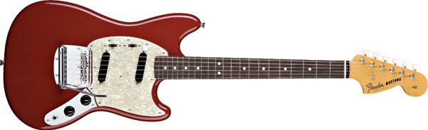 I'm thinking to make a reasonably neat layout of the switches using graphics in MS Word, to create a blank canvas to doodle wires on. Would that help? |
|
|
|
Post by sumgai on Mar 18, 2017 11:49:00 GMT -5
John, From the first page:   I'm also not sure how the two slide switches suddenly metamorphosed into having only two positions each, that'd be a pretty big step backwards, IMO. But there you go, already for you to get a jump start.  HTH sumgai p.s. I still think a simple Telecaster S1 would solve all issues heretoforward discussed or otherwise. Just sayin'..... |
|
|
|
Post by reTrEaD on Mar 18, 2017 14:44:06 GMT -5
merseymale mentioned in his OP this is a Mustang copy so I think I'll just stay out of the way and let John extract as many details as he can . . .
|
|
|
|
Post by JohnH on Mar 18, 2017 15:26:27 GMT -5
sumgai - thanks Id forgotten those pics. But the O/P spec says on/off switches for each pickup, and that is what my scheme uses, so I wanted to check because so far the design is not using the more classic 3 position slide switches from a Mustang.
|
|
|
|
Post by merseymale on Mar 19, 2017 8:35:46 GMT -5
Mm I respect your determination to figure this out! To get the wiring sorted, Id like to help more. Here is a typical Mustang. Apart from yours having a humbucker and single, will your control positions be similar to this? ie, the two switches are above the pickups, and slide horizontally? also, the standard ones seem to have a three position slide switch for each of these. What type of switch will you use? two position? slide or toggle? Are the V and T pots in the same place? I'm thinking to make a reasonably neat layout of the switches using graphics in MS Word, to create a blank canvas to doodle wires on. Would that help? Yes that'll be quite similar (even down to the color!!) the switches above are DPDT simple on/off types (although I have a DPTT type with 8 lugs in my old parts box..) but my goal is to keep it very 'stock looking' & fairly easy to operate so I'd prefer the simpler switches if possible & no toggles. Thanks for your interest & I respect your determination to help me :-) |
|
|
|
Post by merseymale on Mar 19, 2017 8:43:46 GMT -5
John, From the first page: I'm also not sure how the two slide switches suddenly metamorphosed into having only two positions each, that'd be a pretty big step backwards, IMO. But there you go, already for you to get a jump start. HTH sumgai p.s. I still think a simple Telecaster S1 would solve all issues heretoforward discussed or otherwise. Just sayin'..... Very Well spotted with the switches, sumgai! It started life as a mustang copy with no option to phase. As an aside I went to a bar, here in Liverpool, to join in with St.Patricks Day, etc & some creep pinched my iPhone(& my identity for a time-LONG story!) so I've not had access to the net to start my Schematics Training ("sorry, sir, but my Dog ate my HomeWork-honest!!") I'm borrowing a pals iPad for a couple of hours here... As for the S1 well I've always admired them but they are a bit pricey at the moment fo me -there IS probably a way to do the same with rotary switch though but I did find I used the tone a lot when I had the single coils in |
|
|
|
Post by JohnH on Mar 19, 2017 14:23:06 GMT -5
Very sorry to hear about the 'phone. So given the slide switches are just two position, all is well, no need for more complex parts to build your scheme, just the two slide switches and two push-pull pots. Ill draw something up over a few days.
John
|
|
|
|
Post by ashcatlt on Mar 19, 2017 14:57:22 GMT -5
I think John's idea will do it with two poles. One pole sends the top wire of the bottom coil either to the bridge switch or to the bottom wire of the top coil. The other connect the output jack tip either to the volume wiper or the top wire of the top coil. No hanging coils or nothing.
Edit - Heck! When I posted I didn't see that there were two more pages. I see that this is different from what John actually posted on page 2. I have to admit that i didn't think about how my attempt to avoid the hanging coil would affect switching coils with the phase switch...
|
|
|
|
Post by merseymale on Mar 20, 2017 19:03:24 GMT -5
Very sorry to hear about the 'phone. So given the slide switches are just two position, all is well, no need for more complex parts to build your scheme, just the two slide switches and two push-pull pots. Ill draw something up over a few days. John That'd be very good of you -Thank You :-) |
|
|
|
Post by merseymale on Mar 20, 2017 19:15:01 GMT -5
I think John's idea will do it with two poles. One pole sends the top wire of the bottom coil either to the bridge switch or to the bottom wire of the top coil. The other connect the output jack tip either to the volume wiper or the top wire of the top coil. No hanging coils or nothing. Edit - Heck! When I posted I didn't see that there were two more pages. I see that this is different from what John actually posted on page 2. I have to admit that i didn't think about how my attempt to avoid the hanging coil would affect switching coils with the phase switch... Thats OK, ashcatlt, I'm in the same boat as you TBH, it seems it's not one of those easy problems & yet not one that's TOO hard- it just seemed to me to be annoyingly outta reach..! I think when we (for 'we' -in the end- that'll probably be read 'JohnH'!!, let's face it!) get a working easy to follow diagram then I honestly think I won't be the only one ecstatically grateful! I believe there is a useful repeatable concept here that will allow future forum members to come up with tantalising circuits :-) I know I will install such a wiring in at least any guitar I own that has a Bridge 'Bucker |
|
|
|
Post by merseymale on Mar 26, 2017 15:13:12 GMT -5
Very sorry to hear about the 'phone. So given the slide switches are just two position, all is well, no need for more complex parts to build your scheme, just the two slide switches and two push-pull pots. Ill draw something up over a few days. John Looking Forward to hearing back from you as I've been looking over your original Schematic & I'm slowly beginning to notice the patterns 👍 |
|
|
|
Post by JohnH on Mar 26, 2017 16:20:34 GMT -5
Not forgotten! Just been swamped recently. Actually literally, and spent the w/e cutting fallen trees and replacing shifted sand in our riding arena, following storms and heavy rain last week.
|
|
|
|
Post by JohnH on Mar 27, 2017 14:28:46 GMT -5
Here is a first draft of the diagram - there are some important wiring questions to sort out on the HB so its not quite ready to wire yet. Its drawn from the back as you wire it up. The tone control has the phase switch and the GB wiring shown. Pushed in should be in phase if you select a B and N combo, and this setting should be hum cancelling. If you pull the phase knob, it should swap to the other bridge coil and also be humcancelling with the neck. The volume pot has the blower switch - pull to activate it. I also added an optional treble bleed circuit, with vslues assuming a 500k pot. If you are using 250k, the resistor can drop to 120k. On-off switches are the slide switches, as shown, on is when they are pushed towards the neck. The ground wires are shown thick black. On push-pull pots there is usually a handy lug on the outer top face of the switch so that's where grounds are shown soldered. It's much easier than to the pot body. Now tbe questions to be answered. As shown currently, there is some guesswork implied that needs to be confirmed or corrected: 1. Looking at tbe photos, wires to the humbucker coils can be seen soldered to pads at each end of each coil. Does the diagram show tbe right colours at the right ends? 2. What make is the humbucker? As shown the diagram implies DiMarzio or maybe Fender but if it was Seymour Duncan a couple of swaps would be needed. 3. When the HB was wired up before, which two wires were joined and which went to hot and to ground? 4. Which side of the humbucker has the same magnetic polarity as the neck pickup? As drawn, the diagram assumes the hb coil nearest the neck is the same as the neck. Test with a compass or other small magnet. 5. On the neck pickup, when previously wired normally with the bridge, which wire went to hot and which to ground? If we can know all that then the diagram can be fixed so phase and humcancelling can be as good as possible. EDIT just noticed I got output and ground labels reversed! Well it is just a draft, will fix in the final version. Attachments:
|
|
|
|
Post by merseymale on Apr 7, 2017 7:42:49 GMT -5
Not forgotten! Just been swamped recently. Actually literally, and spent the w/e cutting fallen trees and replacing shifted sand in our riding arena, following storms and heavy rain last week. Really Sorry to hear about your weather 😕 Hope all is OK now -it's no consolation that our weather, here, has finally turned out really well!! Thanks again for your thoughtful work, here & I'll get right into it now that College is gearing down for Easter, etc... 👍 |
|
|
|
Post by JohnH on Apr 7, 2017 8:18:17 GMT -5
Ok great. The next step is to see if you can respond to thise questions, then the wiring can be confirmed.
J
|
|
|
|
Post by merseymale on Apr 7, 2017 8:40:14 GMT -5
Ok great. The next step is to see if you can respond to thise questions, then the wiring can be confirmed. J Thanks So Much for your first draft & here are the important wiring answers: You assumed correctly re: a 500k pot but I'm going to flip the switches round to activate pickups toward bridge but HEY that's just me 😉 1. Looking at the wires to the humbucker coils the diagram does show the right colours at the right ends👍 2. TBH I'm not sure of the make of the humbucker (long story but I got some of them very cheap on eBay; took off some of the wraps of wire & switched the blades &/or magnets until I got two real good sounding types) 3. I believe that when the HB was wired up before then the Red & Green wires were joined and the white went to hot with the Black to ground? 4. I reckon the Red&Green wired side of the humbucker -the side currently furthest from the bridge BTW & the one I'd probably prefer to be the 'SC'- has the same magnetic polarity as the neck pickup. It wouldn't be a problem to turn this round though as there is quite the 'swimming pool' under that Pickguard. YEP your diagram assumes right about the HB coil nearest the neck is the same polarity as the neck. So (again!) Good Call! 5. On the neck pickup, when previously wired normally with the bridge, its White wire went to hot and Black to ground but I recently fixed a Fender Texas Special that I got cheap on eBay cos it was broken so MIGHT consider a swap(?) but I admit I did like the Wilkinson Strat type previously so prob won't mess with it -either way the Fender also has Hot=White/Black=Ground too. Although now I think about it are you asking me about which wires are 'coming/going'? Re: your EDIT... Spookily enough this guitar was a real bargain from- well you can guess from where! 😉just cos it hummed whenever metal was touched. Turned out it was because whoever wired it got output and ground labels reversed! (After this AND all your assumptions being correct its now time to cue Twilight Zone theme!) Can't wait to try out your final version & I will compare your 'Rough' Diagram to your Schematic and LEARN..!! |
|
|
|
Post by JohnH on Apr 7, 2017 16:08:12 GMT -5
OK, good info but a puzzle at point 3: If red and green are indeed going to the same coil as they appear, and if they had been previously permanently joined as part of the standard hb wiring, then that coil would have been shorted out. I'm assuming that where the wires appear to go is where they do indeed go, not doubling back to the other coil on the other hidden side of pickup (id doubt it). The pickup manufacturers of the world had a meeting and agreed that between them they will wire their pickups with every possible inconsistent combination of red, green, black and white. Therefore the following link is of no use at all to us!: guitarelectronics.com/guitar-wiring-resources/humbucker-wire-color-codes/But the scheme will definitely work but needs a bit of testing, using a multimeter and/or tapping the poles. A multimeter on a resistance setting of 20k will let you check that red green is a coil pair and black white is a coil pair. Then, we need to test phase of each coil. Can you do this test? guitarnuts2.proboards.com/thread/4938/testing-phase-screwdriver-pull-testYou can use it to test the neck as reference, assuming white is hot, then work out which side of each humbucker coil needs to be towards hot and which to ground to get the same phase as neck. You cn do it with a cheap multimeter, or record into a pc sound card - see if that test makes sense. If not, we will make a guess and be prepared to change it. |
|


 There are several reasons for stealth appearance, but I think the two main ones are:


 So long as the convention is followed, that of "viewing from the backside of the pickguard" (or underside, if you prefer), or else noting prominently that one should view from the topside, then all will be golden. But even then, it never hurts to label terminals with numbers, same goes for switch poles, etc.


