|
|
Post by Jaga on Feb 14, 2019 0:55:52 GMT -5
Hello everyone! I'd say that the question is pretty simple, but I still not able to find the correct answer. There is a common schematics which allows to choose one of 2 pickups (coils) in parallel mode and set them it series / parallel when both are on.  However, I still do not understand what happens if series/parallel switch is series mode and only one pickup is selected. For example, what happens when only neck is on? Or when bridge is on and we're in series? I have a bass wired like this, and when series/parallel switch is in series mode, I still hear some sounds (they are not very lod though) when only 1 pickup is selected while in series mode. Is it possible to have alternate wiring for 2 pickups guitar without such issue? How different is that wiring?  Thank you for your thoughts. |
|
|
|
Post by reTrEaD on Feb 14, 2019 2:08:43 GMT -5
However, I still do not understand what happens if series/parallel switch is series mode and only one pickup is selected. That's a highly flawed design. The only way to get a complete circuit in the series mode is to have both pickups selected. I reckon it is possible to create a wiring diagram that will function properly in series mode with only one pickup selected. It would just require replacing the switched-off pickup with a shunt in series mode and an open circuit in parallel mode. |
|
|
|
Post by Jaga on Feb 15, 2019 1:12:57 GMT -5
Seems that the following wiring doesn't have such issue.  I just added phase switching to famous Wolf's wiring: www.1728.org/guitar10.htmAnd changed SPDTs to DPDTs (I need DPDTs for my applicaiton since I'm using Fender Jaguar Bass). Seems that the time has come to try phase switching on a bass.  From what I see this schematics shouldn't contain errors. Or have I swapped parallel / series switching by mistake in this schematics? |
|
|
|
Post by newey on Feb 15, 2019 7:28:18 GMT -5
First off, I'm going to be a bit technical, to point out that what you've got there is not a schematic, it's a wiring diagram. Not to be overly picky, but we try to write precisely to avoid potential confusion. . . Your diagram will work as advertised, with the proviso that, when either the neck or bridge pickup is selected by itself, the other pickup is left "hanging from hot". That's not a deal breaker, but it can potentially generate some noise, so we generally try to avoid hanging coils where possible. (Wolf's original diagram has the same issue, it's not you  ) What you have here is what we call "binary tree" switching. If you search for that term, you'll find several different takes on the concept floating around here. There are better ways of doing this. YogiB's version below is required reading for you: guitarnuts2.proboards.com/thread/8027/different-on-binary-switching |
|
|
|
Post by Jaga on Feb 15, 2019 15:52:25 GMT -5
Newey, thanks for the replying! Now I know what's difference between a schematic and a wiring diagram. I agree that the more precise terms are the better understanding is. Binary switching looks interersting. However, I don't understand what is going on there. I tried to follow hot signal path from the 5th terminal of phase switch considering that 2 pickups are in "series" position (first given example). Attaching the picture how I tried to follow the path with bold green line. Not sure where the signal goes next? Probably, I miss some things and my logic is not correct. I would be grateful if one could point me to the right direction. UPD. OOPS. Seems that I forgot to go from 5th to 6th terminal of the phase switch. My bad. UPD2. Do you think it would be possible to add a phase switch for one of the coils before series / parallel switches for S-S application? 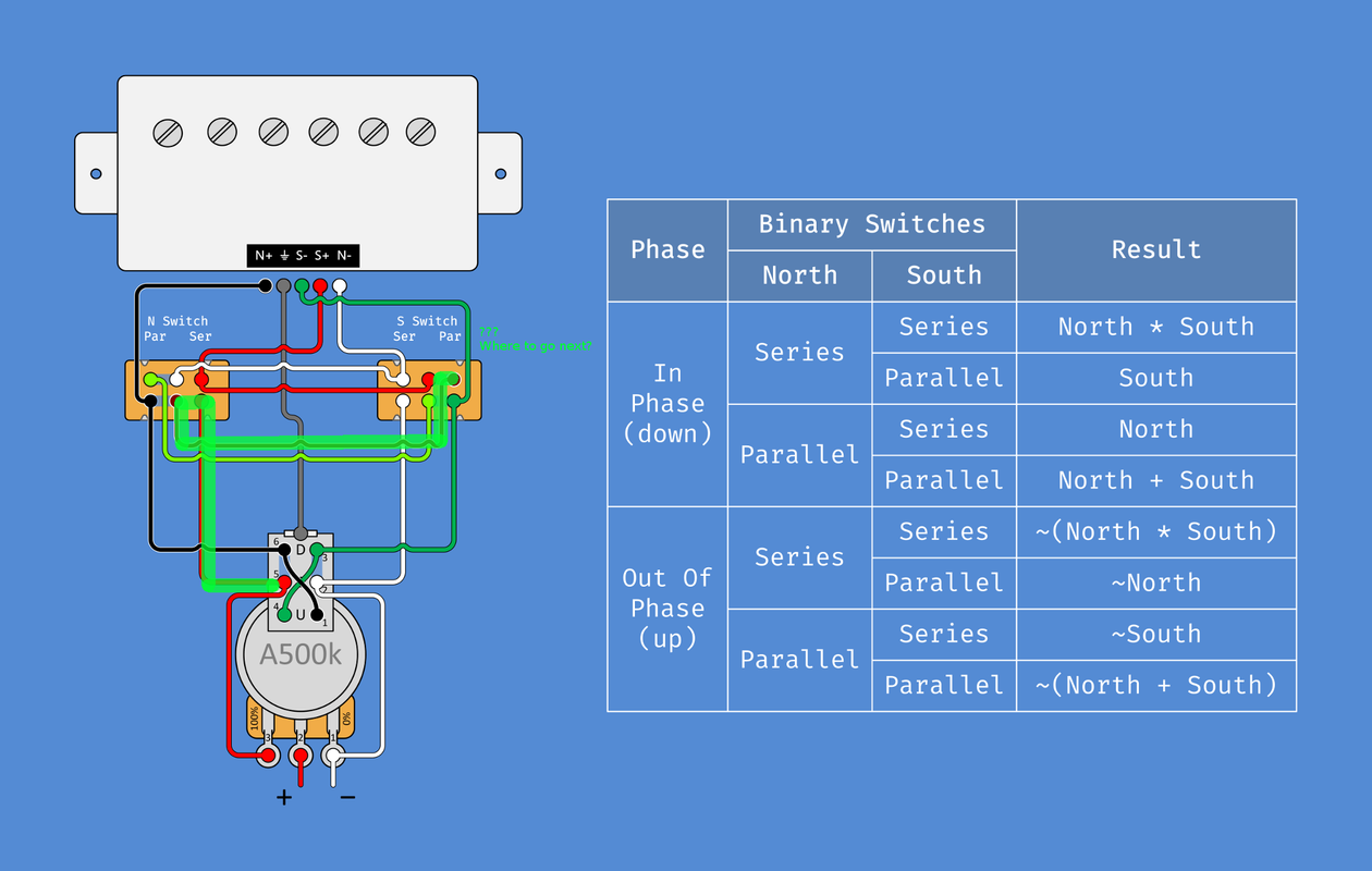 |
|
|
|
Post by newey on Feb 18, 2019 6:50:21 GMT -5
To start, I was not suggesting you follow Yogi's idea exactly, it was more of a reference for you to binary tree switching. Yogi's post has a link to the original ChrisK post describing this switching as well, so I thought it would be a good compendium.
In Yogi's design, the phase switch has to be as it is wired, so that the coils selected will be hum-cancelling when out of phase. You can put the phase switch directly after one or the other pickup, but the OOP setting won't be hum-cancelling. Or, if you make the OOP setting hum-cancelling, then the "regular" 2-coil combos won't be.
Note also that, while Yogi's diagram shows the wiring for 2 coils of a single HB, the same wiring can be used for two individual coils. It can also be used, as is, for two HBs if one doesn't care about coil-cutting. Or, it can be reiterated for each one of a 2 HB setup to give the coil cuts, in what ChrisK called a second-order binary tree.
Your green line is of no help to follow the series path, since the green line obliterates the underlying diagram. But it looks like you figured that out anyway, correct?
|
|
|
|
Post by reTrEaD on Feb 18, 2019 8:39:09 GMT -5
This might be easier to follow as it's a schematic rather than a wiring diagram and it's unencumbered by the brilliant but highly specialized phase switch incorporated in Yogi B 's design. guitarnuts2.proboards.com/post/27667/thread  EDIT: EDIT:I see PhotoBuggit is being a PLB this morning so I rehosted that image.  |
|
|
|
Post by Jaga on Feb 19, 2019 0:17:05 GMT -5
From what I see (please correct me if I'm wrong), in this kind of wiring N+ (North+) contact is always connected to the signal hot. Can this be an issue? Trying to understand how things should work.  |
|
|
|
Post by reTrEaD on Feb 19, 2019 6:47:23 GMT -5
From what I see (please correct me if I'm wrong), in this kind of wiring N+ (North+) contact is always connected to the signal hot. Correct. That's what we call 'hanging from hot'. It's a minor issue. It can add slightly to the hum and noise. Avoid it when possible, accept it when it can't be avoided. |
|
|
|
Post by Jaga on Feb 19, 2019 15:50:23 GMT -5
From what I have understood, Wolf's wiring (which is in 1st post) has also the issue with hanging coils. Why then binary tree wiring (with 2 DPDTs) is better than Wolf's wiring since is more complex? |
|
|
|
Post by newey on Feb 19, 2019 23:10:26 GMT -5
Rt said, in response to jaga: And then jaga reasonably asked: And so, we go down the merry path of error . . . Wolf's diagram uses SPST switches to perform the binary switching.(It's still binary switching, same idea). And the unused coils do indeed hang from hot, no way around that with SP switches. The original wiring diagram jaga posted also had hanging coils, even though using DPDT switches, as I pointed out in reply #5 above. Even though DPDT switches were shown in the diagram, only one pole of each switch was used, so the switches could just as easily have been SPDTs. Electrically, it's equivalent to wolf's diagram. However, the schematic posted by RT does not have any hanging coils- because the other half of the DPDT switches is used to disconnect the unused coil at both ends. IOW, this statement is incorrect (and RT was incorrect to agree with it): Let's look again at the schematic. First off, the coils are designated "A" and "B" since, schematically speaking, the circuit could be wired with either the neck as coil A or as coil B, and it would function the same either way. But for the sake of discussion, we'll arbitrarily designate coil B as the bridge pickup and coil A as the neck. Switch 1 controls coil B. Switch 1 has 2 poles, designated as "A" and "B". Note that the two poles of the switch are shown as separated from each other on the diagram- the dotted line links the 2 halves of switch 1. Switch 2 controls coil A; both poles of this switch are shown next to each other- see the other dotted line connecting the 2 poles. (The dotted lines are just added for convenience in looking at the diagram.) As shown by the diagram, the coils are in the parallel setting. The B- is permanently connected to ground at the bottom of the switch. The B + is not permanently connected to hot, it is switched via SW1A. With SW1A as shown in the diagram, B+ connects to the output for the parallel setting. Now, however, if we flip SW1A, the B + connects to SW2A. If we do not move SW 2, then B+ isn't connected to anything, and is not therefore hanging from hot. If we flip SW1 and also flip SW2 as well, then the B + connects to A- to give us the series setting. The series path gets finished by SW1B, which then connects the A+ to output. As for the other coil, the neck or "A" coil, it is only connected to hot via SW2A in the parallel position. When we use SW2 to switch that coil "off", both A+ and A- are disconnected and there is no hanging from hot issue with coil A either. To sum up, the whole reason to use DPDT switches here is to avoid the "hanging from hot issue". RT is correct, however, that it probably isn't a big deal to have a hanging coil, it's more of a "best practices" thing to avoid it where possible. Since the cost difference between DPDT switches and SPST ones is negligible, and availability of both types is about the same, you might as well use DPDT switches. Also note that, though we haven't expressly said so, but whether you use DPDT or SPDT switches, they must be of the "on-on" variety. |
|
|
|
Post by Jaga on Feb 24, 2019 22:24:44 GMT -5
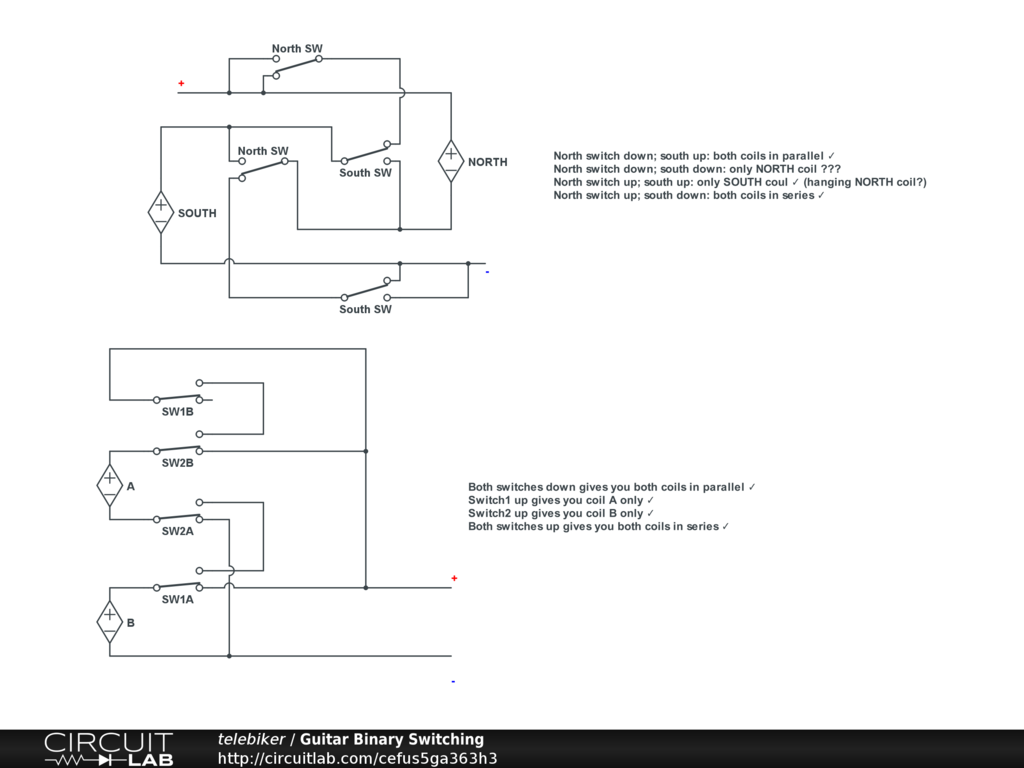
Thank you very much for the patience and explanation. Trying to understand binary wiring magic, would like to know, if both schematics below are electrically the same (if we eliminate out-of-phase switch from the first one)? 1 = 3 2 = 4 I wanted to find the answer by myself, so I imagined there's no phase switch on the first one, registered on circuitlab.com and drew both schematics. I also eliminated tone / volume pots from the second one. Second one did not mention coils polarity, so I had to guess it. I hope that I did everything correcly. I came to the following conclusions regarding the schematics below:
Basiaclly 1'st schematic should be identical to the 3rd; and 2nd should be identical to the 4th.
- 3rd (upper) schematic: when north switch is down and south also down, only NORTH coil should be enabled. However, what I can see is that signal goes from NORTH- to SOUTH+ (via upper pole of south SW). Is this correct? Or I don't understand something?
- 3rd (upper) schematic has hanging coil if only SOUTH coil is selected
- 4th (lower) schematic works without mentioned issues. Seems that they are not identical from the electric point of view.
I wonder if someone having more experience than me could confirm / disapprove both schematics? Switches are in the position when both coils are in parallel on both schematics. It can be opened in online editor here: www.circuitlab.com/circuit/efus5ga363h3/guitar-binary-switching/
Attaching also an image. Thank you!
3 and 4.
|
|
|
|
Post by newey on Feb 25, 2019 0:26:17 GMT -5
I'm a bit confused by all the schematics, as far as which one is which. There are four in all, from top to bottom, so for the purposes of discussion, I'll call them numbers 1 through 4.
1) This one has the color-coded switches, with the phase switch. I will assume this is the one you have drawn. It is incorrect, we'll discuss why below.
2) This is Unklmickey's diagram, as reposted by RT in the earlier post in this thread. As I pointed out before, it uses DPDT switches to avoid any coils hanging from hot. It will work correctly. When both switches are "up", coils are in series, when "down", the coils are in parallel, when one is up, the other down, one gets one coil; with the other down, other up gives the other coil alone.
3) This one appears to be the same as #1 without the phase switch. It suffers from the same problems as #1.
4) The last schematic is identical to Unklmickey's, and features the same switch operations. It is correct.
So, why are schematics numbers 1 and 3 incorrect, while 2 and 4 are correct? Look a little closer at 2 and 4 and you'll see the problems with 1 and 3. To accomplish the binary tree switching, all 4 switch poles are switching something. In schematics 1 and 3, the pole shown furthest down on the diagram is doing nothing, it is switching a wire from ground to ground. Similarly, the pole shown at the top of the diagram is also switching nothing- it switches a wire from hot to hot.
Look at either of the good schematics, 2 or 4. Of the 4 wires from the two coils, only Coil B's negative is permanently attached to ground; the other three wires go to the switches. Both ends of coil A are switched.
Now notice that, on diagrams 1 and 3 (ignoring the phase switch on #1 for the moment), the "hot" end of the North coil is always attached to hot, in addition to the Negative of the South coil being grounded. On diagrams 1 and 3, only 2 of the 4 pickup leads are being switched.
I think you'll "see" the error if you compare the coil wiring of unk's schematic to yours. The phase switch may have confounded you a bit, but it doesn't really affect the binary scheme. You can think of the phase switch as a separate module that is wired across one of the two coils before we get to the binary switching.
EDIT:BTW, if you're wondering what diagrams 1 and 3 actually do (and ignoring the phase switch), both switches "up" (understanding that "up" and "down" are arbitrary designations with a schematic) gives the coils in series, both switches "down" gives the coils in parallel, but having one switch up and the other down does not give single coils. On both 1 and 3, having one up, one down gives (N X S) + S. In other words, the north and south coils are in series with each other, and both are in parallel with the South coil alone. Flipping the switches the other way, one down, other up gives exactly the same combination. Not at all what you wanted for those positions!
|
|
|
|
Post by Jaga on Feb 25, 2019 0:44:49 GMT -5
I'm a bit confused by all the schematics, as far as which one is which. There are four in all, from top to bottom, so for the purposes of discussion, I'll call them numbers 1 through 4. Sorry if my previous post was too confusing. I have edited it a bit to make it clearer. Actually, I have taken schematic number 1 from that thread: guitarnuts2.proboards.com/thread/8027/different-on-binary-switching (you suggested me get acquainted with that, and it was great new info for me ) I drew it from scratch using different tool to have better understanding what is going on. I have also taken schematic posted by reTrEaD and also drew it. So, in my previous post 1=3 and 2=4 (but in 3rd schematic phase switch is eliminated and in 4th volume/tone knobs are put away). Probably, I've eliminated phase switch incorrectly. Thank you for nice and clear explanation what is going on. Do you think that that thread should be updated with your explanation? I will take Unklmickey's diagram as a reference for my project. Would like to add volume pot, preamp switch and a killswitch. Will post wiring diagram once done. |
|
|
|
Post by Yogi B on Feb 25, 2019 4:20:44 GMT -5
Yup that's mine. Nope, you correctly eliminated the phase switch you just didn't go far enough... So, why are schematics numbers 1 and 3 incorrect, while 2 and 4 are correct? Look a little closer at 2 and 4 and you'll see the problems with 1 and 3. To accomplish the binary tree switching, all 4 switch poles are switching something. In schematics 1 and 3, the pole shown furthest down on the diagram is doing nothing, it is switching a wire from ground to ground. Similarly, the pole shown at the top of the diagram is also switching nothing- it switches a wire from hot to hot. When the phase switch is eliminated, the outer poles of each switch are redundant, yes -- their purpose it to alter how the binary switching works in conjunction with the phase switch. However that's okay, to achieve binary switching one only needs two SPDTs (if you don't care about fully disconnecting the unused coil when only one of the two is selected). This can be done in one of two ways, either: - you can disconnect one end of the unused coil leaving it 'hanging', note that a coil may hang from hot, ground, or (in more complex wiring) any place in between, be we don't consider a coil hanging from ground to have as much (if any) negative affect;
- or, you can (as my version does) leave both ends of the coil connected to the circuit, but shunt it by shorting its ends together, though there is an argument that this may also still have an undesirable side effect, see Shunting Coils - 'Beware the Tone-Sucker'!
Unk's diagram avoids both potential issues by using the extra poles of the DPDTs to disconnect both ends of the unused coil. |
|
|
|
Post by newey on Feb 25, 2019 6:42:03 GMT -5
Yes, my discussion was premised on the idea of avoiding hanging coils. If this is not a concern, SPDT switches are enough.
But, Yogi, your diagram had me confused- that tricky phase switch had me confused. So I apologize, looking again, the diagram with the phase is OK. #3, where the phase has been eliminated, is the problem.
|
|
|
|
Post by reTrEaD on Feb 25, 2019 8:54:59 GMT -5
I will take Unklmickey's diagram as a reference for my project. Would like to add volume pot, preamp switch and a killswitch. Will post wiring diagram once done. The specific application matters when making choices like this. In your case, where you're dealing with two pickups and want to add the option put one of them out of phase, UnklMickey's diagram will serve as an excellent starting point. Just add the traditional 'x' type phase switch directly to one of the pickups and add your kill switch to shunt the volume control. In the case of managing two coils of HB, Yogi B's diagram provides a feature that can be very useful in that specific application. |
|
|
|
Post by reTrEaD on Feb 25, 2019 9:03:38 GMT -5
btw, that circuit lab link is rather interesting. Feel free to open a new thread in this board to discuss the merits of that editor, if you like. If not, I reckon one of us might do so, either on this board or perhaps in Reference Articles or Useful Links To Other Sites |
|
|
|
Post by Jaga on Feb 25, 2019 15:32:06 GMT -5
Circuitlab is interesting, but, unfortunately, you can save circuits only in paid version and there is no trial.
Thanks everyone for the explanation! It was a tricky thing with that phase switch.
|
|
|
|
Post by Jaga on Mar 15, 2019 11:10:04 GMT -5
Based on the discussion created a wiring diagram for a two single coil guitar with 2 DPDT switches for series/parallel/individual switching, 1 phase switch and a preamp switch. Questions and corrections are very welcome. From my point of view it looks good, but second look is always worth it. Thank you.  |
|
|
|
Post by reTrEaD on Mar 15, 2019 11:39:01 GMT -5
Jaga if your DPDTs are slide switches (or switches on a push-pull pot) the positions you indicate will provide the results you expect. However, toggles work in the contrary direction. In other words, if the toggle is 'up', the poles will connect to the throws on the bottom.
|
|
Deleted
Deleted Member
Posts: 0
Likes:
|
Post by Deleted on May 8, 2019 13:28:38 GMT -5
I was working on how to use less switching. So i found a Switch and changed its inside (just a Disc) ![]()  Neck Pickup + to OUTPUT Neck Pickup - to Ring 2 Bridge Pickup + Ring 1 (Outer Ring) Bridge Pickup - Ring 3 Output to Ring 4 Ground to Ring 5 (Inner Ring) The Inner Ring (Ring 5) hooks up to the Red Dots inside, the long zig zag blocks (apart from the Outer Ring link up) This should let have 0) Off 1) Bridge 2) Neck & Bridge 3) Neck 4) Neck & Bridge Phased 5) Bridge Phased 6) Neck Linked to Bridge Phased 7) Neck Linked to Bridge   |
|
|
|
Post by Jaga on Jul 20, 2019 17:45:53 GMT -5
Based on the discussion created a wiring diagram for a two single coil guitar with 2 DPDT switches for series/parallel/individual switching, 1 phase switch and a preamp switch. Questions and corrections are very welcome. From my point of view it looks good, but second look is always worth it. Thank you.  Basically, I like this schematics. But I have an instrument with a pot control plate with 2 holes for 2 potentiometers. And I'm using only one pot (volume). I don't need a tone control since I have an active preamp. Right now the second hole is covered by "fake" pot with a knob just for aesthetics reasons connected to nothing . However, I don't like something like this. Also, I really miss a killswitch. I can exchange the volume pot to push-pull one. But how can I find a usecase to the second "fake" potentiometer? Would appreciate any crazy ideas. |
|
|
|
Post by newey on Jul 21, 2019 7:49:15 GMT -5
Well, I suppose you could find a spring-loaded push-button style momentary switch that would accept a knob to match your volume control,or perhaps you may need to modify the pushbutton part to accept the knob. You could just use a P/P pot for a kill switch, but that would be a "click-on, click off" situation which wouldn't allow for the staccato machine-gun effect.
|
|
|
|
Post by Jaga on Jul 22, 2019 14:55:46 GMT -5
Well, I suppose you could find a spring-loaded push-button style momentary switch that would accept a knob to match your volume control,or perhaps you may need to modify the pushbutton part to accept the knob. You could just use a P/P pot for a kill switch, but that would be a "click-on, click off" situation which wouldn't allow for the staccato machine-gun effect. That sounds reasonable. From that point of view having usual volume pot (not push-pull) and separate momentary killswitch would be more useful. |
|
|
|
Post by Jaga on Nov 19, 2020 20:21:02 GMT -5
I've wired this several months ago. I'd say that it is recommended wiring for 2-single guitar However, the wiring itself takes some time. I know how to make it more simple, a PCB is needed.
Also, originally the stock preamp had no true bypass, and I wanted to fix it. I found an instruction how to do this, but I was not very good in soldering and I just have broken it. Luckily, I was able to fix the passive mode, so I could still use the instrument. (Couple of month later I sold the neck, and the bass was disassembled for several years.) Later I found the guide how to change stock preamp with EMG BTS Control and did the changes. Currently I'm not satisfied with it, because this EMG is not reliable, requires a lot modifications to fit, has several components I don't need, and it is pretty expensive for the small PCB. I'm going to replace it with something else. |
|
|
|
Post by Jaga on Nov 21, 2020 19:33:22 GMT -5
BTW, have a thought regarding binary switching design. If using mustang switch, phase option can be added to the series or parallel (or both). What do you think? |
|


 )
)


