|
|
Post by studiostriver on Nov 4, 2019 6:19:35 GMT -5
I agree with newey. It would be best to check the switch in case any connections need moving position. Those 4pdt on/on/on switches are fairly uncommon and I've never personally seen one in real life . The thing about them is that, with lever up, all connections are down to the lower lugs, with lever down, all connections are up. But in the middle setting two are up and two are down. I think, as I drew it, it's the most common arrangement, left to right: down-up-down,-up. But several other arrangements are possible so might as well check to be sure. Also, your hex-screw pickups don't look like they give away many clues as to north and south and which physical coil is to which wire pair. Best to do some tests before wiring, even if the maker gives you data. Let's discuss once you get them. This scheme has quite a lot of thinking in it to make sure that every setting is as hum-cancelling as it can be (other than the single coil on their own), including all pairs of coils in and out of phase. So if any polarity or wire is swapped, it will likley go wrong! I'll probably do a few minor graphical cleanups on the diagram, though so far I reckon the info is correct. But download it again when it's time to start. Good luck with getting it built. And the price of using it, as with all designs on GN2, is some feedback in due course, on how it goes and what you think of it! I`ll take that into account. Hopefully we will somehow find a way to make it work. Also I can wait for second cleanup diagram, and when pickups arrive I`ll try to do things that I possibly can that you ask from me in order to see where is south/north coil placed. As for the switch,hm.. I hope my tech will figure it out. Also if needed i`ll buy another 4pdt on/off/on switch and put it into JP7 to pass confusions,just need to find high quallity one. This guitar deserves it. ..... And the price of using it, as with all designs on GN2, is some feedback in due course, on how it goes and what you think of it! Err, that's not quite all of the price. We also need to have audio clips posted (or even full video clips) in order that we can hear the final results. Other potential modders often find such clips useful.
sumgai
Its not a problem.I shall do some audio clip tests if needed foro you guys when project is finnished when I take it home into my home studio. |
|
|
|
Post by studiostriver on Nov 4, 2019 7:10:06 GMT -5
|
|
|
|
Post by JohnH on Nov 4, 2019 13:46:07 GMT -5
That switch should work, it is a dpdt on/off/on so it will use the inset diagram on the drawing. I see it mounts in a 12mm hole, is that the hole size that you have in the guitar? What is the size of the current switch?
If the current one is a 4 pole on/on/on, it will definitely work, after a few checks so it can be wired the right way
|
|
|
|
Post by studiostriver on Nov 5, 2019 16:10:52 GMT -5
That switch should work, it is a dpdt on/off/on so it will use the inset diagram on the drawing. I see it mounts in a 12mm hole, is that the hole size that you have in the guitar? What is the size of the current switch? If the current one is a 4 pole on/on/on, it will definitely work, after a few checks so it can be wired the right way I have quite big switch there. And good to know on/on/on should work,I hope my tech will figure it out quickly.  |
|
|
|
Post by studiostriver on Feb 12, 2020 14:39:56 GMT -5
|
|
|
|
Post by studiostriver on Feb 13, 2020 12:16:28 GMT -5
I read all messages on this topic again and I see there will be revision of the scheme. I`m not in a hurry since I`ll probably on the end of the month have time to take it to luthier.
|
|
|
|
Post by JohnH on Feb 19, 2020 4:07:18 GMT -5
Heres an update, no real changes, just a couple of corrections, ready for a check: ![]()  |
|
|
|
Post by reTrEaD on Feb 19, 2020 11:40:59 GMT -5
Heres an update, no real changes, just a couple of corrections, ready for a check: Hey JohnHThe schematic looks very familiar. I see the GN2 series-override switch you and borsanova made famous. I see the electrical 'stacking' of the Neck pickup with the North on top and the Bridge with the South on top to maintain hum-canceling when the HBs are split. I see the end-swapping phase switch with the management of splitting accomplished by the series link going to either hot or ground to maintain hum-canceling by swapping coils when the phase is reversed. These appear to be meshed together correctly so I'll confirm the schematic section is correct. The wiring diagram will require more time. I don't currently have a color printer, just a B&W laser printer. So I'll have to examine it carefully on a screen. My eyes go a bit wonky after a short period of screen time so I'll break that into a few sessions to do a proper job of it. Probably finish this evening. |
|
|
|
Post by JohnH on Feb 19, 2020 14:14:20 GMT -5
reTrEaD - many thanks!
|
|
|
|
Post by reTrEaD on Feb 20, 2020 23:56:50 GMT -5
Hey JohnH, I'm unable to find any errors. The only teeny tiny criticism would be the choice of a black jumper between the upper-right throw of the coil cut switch and the upper-right throw of the phase switch. I think it would have more clarity if that were red or pretty much any other color than black. Also, a few of the connections like the upper-right throw of the S/P switch could be a bit prettier. But none of that merits an update. |
|
|
|
Post by JohnH on Feb 21, 2020 1:43:54 GMT -5
Thanks indeed! Im glad I haven't lost it yet!
So to studiostriver, the drawing is reviewed, and you have the parts. If you want to try it then it's good to go.
|
|
|
|
Post by studiostriver on Feb 21, 2020 16:14:09 GMT -5
Wow,just wow. Guys , you are nothing short but amazing. John and reTrEaD I really cant thank you enough, cause without you I couldn`t even imagine to have such a amazing scheme to play with in future to come and hopefully gonna use on my future projects I planning to record.
I downloaded the scheme,and during the begining of the next month gonna send it for modding to my guitar tech.Guitar will stay for about half month or even more in his place cause this guitar has a lot of modding to be done.
When he finish everything and I return with the guitar I`m gonna make new post with new pictures,and what is most important with audio clips for you to hear the results.
Kind regards and God bless you,
Dado.
|
|
|
|
Post by studiostriver on Mar 13, 2020 11:03:25 GMT -5
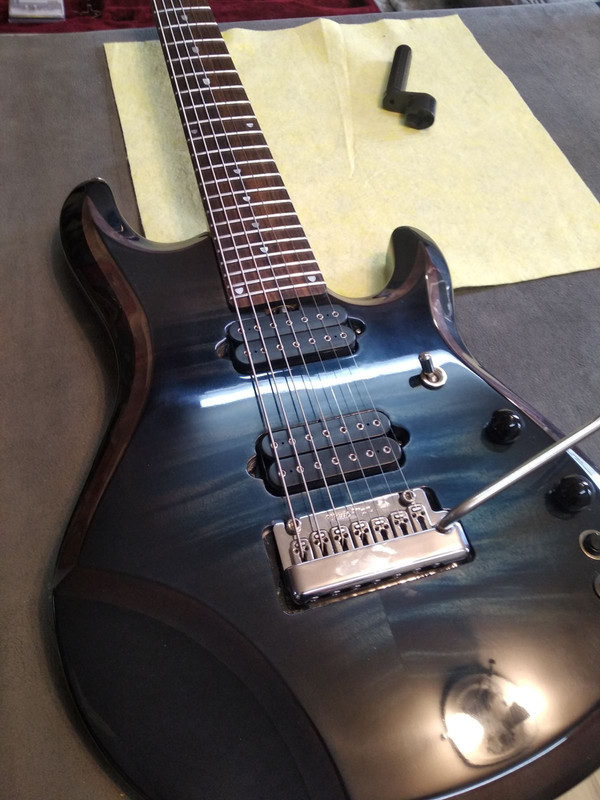
Going tomorrow finally to my guitar luthier with guitar,all parts and the scheme.  |
|
|
|
Post by studiostriver on Apr 21, 2020 6:51:07 GMT -5
|
|
|
|
Post by studiostriver on Jun 3, 2020 21:38:14 GMT -5
|
|
|
|
Post by newey on Jun 4, 2020 5:18:38 GMT -5
SS-
This has been a long journey, but the end result is beautiful, and I hope the scheme lives up to what you wanted. Thanks for showing off the finished product!
|
|
|
|
Post by studiostriver on Jun 4, 2020 5:34:35 GMT -5
SS- This has been a long journey, but the end result is beautiful, and I hope the scheme lives up to what you wanted. Thanks for showing off the finished product! Hi Newey. We havent havent talked for quite some time,and indeed journey was very long,but I think ending results are very good. Guita rlooks upgraded in every sense. The scheme is conencted by my luthier,so i havent checked it,but I`m pretty sure it will fulfill all my needs i ever dreamed of. Guitar will come to my house in about 2/3 days,and I`ll do a proper testing of all scheme combinations and put here for you to hear it. I`m very thankful for your help. Without you guys I couldnt make it into reality. |
|
|
|
Post by frets on Jun 4, 2020 10:28:20 GMT -5
Your guitar is so sweeeet !!
|
|
|
|
Post by JohnH on Jun 4, 2020 15:14:23 GMT -5
That is absolutely a beautiful thing. I'd come to your gig just to look at your guitar!
|
|
|
|
Post by studiostriver on Jun 4, 2020 18:05:45 GMT -5
That is absolutely a beautiful thing. I'd come to your gig just to look at your guitar! Hi John. I`m very glad you like how it looks. I waited so much time,and at the end it looks it worth it. Without your skills certainly I couldnt make it into reality. My luthier told me that he had no problem with soldering,the scheme was pretty clear and straightforward. Cant wait it to get to my home,so I can work with it from now on daily basic and exploring vast combinations.  |
|
|
|
Post by studiostriver on Jun 9, 2020 13:36:17 GMT -5
Unforunately i got problem with the scheme. My luthier saying everything sound very very low in volume. He tried everything and re soldered everything 2 times,and tomorrow he will call his friend who is one of the best electricians in the region to check it out.
If you can add any recomendation I would be much appreciated, but I hope they will solve it tomorrow.
Kind regards to all.
|
|
|
|
Post by JohnH on Jun 9, 2020 16:35:52 GMT -5
Sorry to hear that. Given that he has worked carefully, and also that we checked the design here first, I reckon the most likely issues would be either that the actual switches are different in some way to how they are interpreted in the diagram, or htat pickup wire colours are different. But your pickups are stock Dimarzio aren't they?
Anyway, there's a few of diagnostic checks that are easy to do, but might take some time given that the guitar has 24 different settings:
Based on resistance measurements:
1. Measure resistance across the tip and barrel of a guitar cord plugged into the guitar jack
Select what should be a simple setting like a full humbucker
Sweep the volume pot from max to min. It should start at the resistance of the pickup or a bit less, rise until it is about 1/4 of the value of the volume pot, then drop to zero as the pot reaches min volume.
2. As above, volume at max, sweep the tone pot. It should make no change.
3. (time consuming) knobs at max. Carefully step through each of the 24 switch settings measuring resistance. Mark the resistances onto a copy of the scheme (I suggest in the column marked sw1=main) post that here
4. Phase tests, checkout the 'screwdriver pull off test' in our reference section, but Id suggest to do 3 first
|
|
|
|
Post by studiostriver on Jun 9, 2020 18:54:34 GMT -5
Sorry to hear that. Given that he has worked carefully, and also that we checked the design here first, I reckon the most likely issues would be either that the actual switches are different in some way to how they are interpreted in the diagram, or htat pickup wire colours are different. But your pickups are stock Dimarzio aren't they? Anyway, there's a few of diagnostic checks that are easy to do, but might take some time given that the guitar has 24 different settings: Based on resistance measurements: 1. Measure resistance across the tip and barrel of a guitar cord plugged into the guitar jack Select what should be a simple setting like a full humbucker Sweep the volume pot from max to min. It should start at the resistance of the pickup or a bit less, rise until it is about 1/4 of the value of the volume pot, then drop to zero as the pot reaches min volume. 2. As above, volume at max, sweep the tone pot. It should make no change. 3. (time consuming) knobs at max. Carefully step through each of the 24 switch settings measuring resistance. Mark the resistances onto a copy of the scheme (I suggest in the column marked sw1=main) post that here 4. Phase tests, checkout the 'screwdriver pull off test' in our reference section, but Id suggest to do 3 first Hi I`m very frustrated,but I hope we will manage it somehow and find the way to make it work. My luthier live in different town I have to write him everything you wrote via viber unfortuantely. My pickups are Di Marzio Ionizers 7 string model/black version : www.dimarzio.com/pickups/7-string/ionizer-7-bridgewww.dimarzio.com/pickups/7-string/ionizer-7-neckThe switches I have for volume and tone are push/push from Di Marzio that Music Man uses,this one: dubaldomusic.com/ebmm-500k-push-push-pot?search=&category_id=86 I have in for pickup selector Switchcraft Gibson style: www.switchcraft.com/Product.aspx?ID=3338The rest is Di Marzio dpdt on/off/on switch i bought on ebay, you can see a picture of it in previosu messages. www.amazon.com/DiMarzio-3-Position-DPDT-Mini-Switch/dp/B000H18RXYwww.dimarzio.com/hardware/switches/dpdt-mini-switch-3-position-onoffonAnd the last switch is Tesi kill switch bought on ebay too,high quallity switch. Thats it. tesiswitch.com/shop/ols/products/tesi-ido-super-m-10mm-metal-momentary-push-button-guitar-kill-switch-ts-ido-spr-mwww.amazon.com/Tesi-Switch-Super-Momentary-Guitar/dp/B07MXKGQ6JMy luthier is dude of 61 years,and I sincerly doubt he will have nerves doing the measures.Especially with all 24 combinations.I wish I live near so I can took it and do all measures,but unfortunately he lives in different part of the country which take me 5 hour of driving. I`l speak to him and see what option for me are. This really brings me down a lot,especially due to fact I waited a lot for all these mods,and know the scheme is not working.I`m on the edge of nerve break up, lest hope everything will end up fast and that mistakes maybe were not so huge in soldering.I keeping my fingers crossed not to make this into nightmare. |
|
|
|
Post by JohnH on Jun 9, 2020 19:29:12 GMT -5
The advantage of tests like these is that they are all outside the guitar, no desoldering and rework yet, It gives us a lot of information so we can help.
|
|
|
|
Post by studiostriver on Jun 9, 2020 19:37:38 GMT -5
The advantage of tests like these is that they are all outside the guitar, no desoldering and rework yet, It gives us a lot of information so we can help. Are all my switches and pickups work as predicted I put in info at least? I`ll talk tomorrow with the luthier about this,and see what my chances are. Beside this I`m not too much healthy dude,so maybe there will be some delays in my answers,I going to see a doctor numerous times during this week. |
|
|
|
Post by JohnH on Jun 10, 2020 0:57:35 GMT -5
All the parts seem fine to me. I'm sure we can figure it out!
|
|
|
|
Post by studiostriver on Jun 10, 2020 4:56:36 GMT -5
All the parts seem fine to me. I'm sure we can figure it out! I`m glad to hear that. If scheme is perfectly correct and I if all parts i work as predicted then its all up to his reading of the scheme to find the mistake in soldering. |
|
|
|
Post by studiostriver on Jun 10, 2020 13:34:41 GMT -5
I explained my luthier the situation,he said he will first try to re solder it with his friend who is electrician engineer,and if they failed,then he will do resistance measurings.
|
|
|
|
Post by studiostriver on Jun 11, 2020 9:37:49 GMT -5
The only favor I may ask if it snot too much hustle to yo guys is that you made more cleaner drawing of the scheme? Maybe some edges of black cables are clear enough.
I imagine it will be of great help to my luthier.
|
|
|
|
Post by JohnH on Jun 11, 2020 18:14:45 GMT -5
I don't have any tools or skills to make a better drawing. Normally my drawings are ok for others to follow but it is quite a complex scheme. Are there parts that are not clear?
things to note:
All wires connect to switch or pot lugs. Where one wire crosses another wire in the diagram, they are not connected
For the two push-push pot/switches, the cases of the switch are grounded. The diagram shows a thick black wire connected to the top of the switch bodies, where usually there is a lug to solder to
Instead of resoldering it all again, those tests, even just the first one, might quickly identify the issue with no work
|
|