|
|
Post by JohnH on Sept 18, 2019 3:28:38 GMT -5
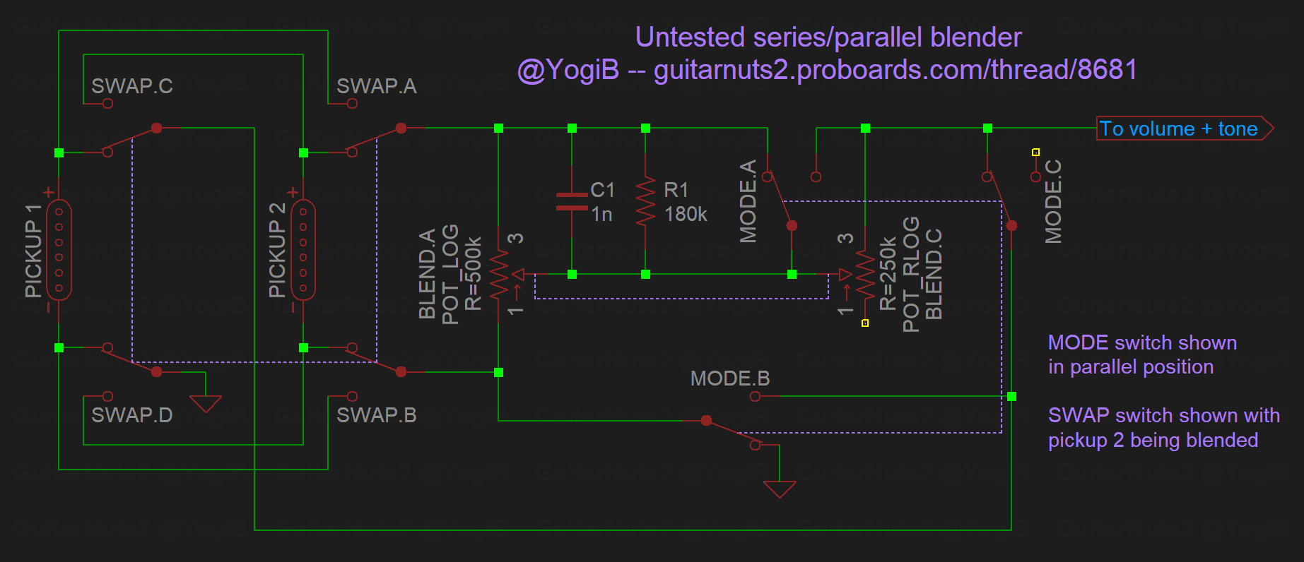
My option B.3 above represent my attempts to iron out the kinks in both series and parallel blending, so JohnH what do you make of this: (I appear to have been overly optimistic in my previous mention of the above as I can only see how to achieve it with at least 7 poles across the two switches, but that's probably not too significant a step from two 3PDTs since they'd likely be implemented using 4PDTs anyway.) Clever use of the direction of log and reverse log part pots! Need to mock it up somehow to hear what the mixes would be like, maybe using two seperate pots for a bench test. I think Spice modelling could also explore it usefully, |
|
|
|
Post by Yogi B on Sept 18, 2019 6:24:27 GMT -5
I missed this until just now. BTW, what happened to the single no-load pot option, which would give maximum "Quack"? Is that still an option? In that case, I'd opt for more quack. I just glossed over that option when replying to John because it wasn't relevant to what I was saying, but as he points out: "It gives a somewhat quirky interaction with reduced volume" more specifically I covered this issue in my third point in Reply #19 (just under the switching table). But that's the fault of it being '50s wiring, not the fault of it being a no-load pot. Therefore, if desired, you could modify each half of a dual gang pot to be no-load.
I was thinking more about this 2-volume system Its a bit trickier than Id thought! The key issue seems to be getting the other volume pot out of the circuit when only one pickup is used. I'll keep looking. Hopefully 4pole S1 switches may help! I think the following should do it, but I'm left pondering over if it is possible to automatically disable the series bypass cap in position 5 -- I reckon so, but it'll require quite a bit of rearrangement -- I'll have to think about that one further. 
|
|
|
|
Post by JohnH on Sept 18, 2019 8:00:57 GMT -5
Great drawng!
I think I see in there, the issue that im struggling with:
For example, when B only is selected, in parallel mode under the control of Volume 2, is not Volume 1 still connected, loading the output?
Im needing 6 poles on the superswitch!
|
|
crillev1
Apprentice Shielder

Posts: 34 
Likes: 3
|
Post by crillev1 on Sept 18, 2019 14:15:05 GMT -5
Yogi BHoly .....!!!! Wow, thank you so much for your effort. Like I said earlier, we hobbyists understand graphic presentation much easier than verbal instructions.  Your diagram is the most beautiful and clear guitar electronics layout I have ever seen. I can't wait until I get my Burns Tri-sonics in a few weeks and test this layout. Your diagram reminds me of Phostenix diagrams. Wait a minute... I just had a thought (not related to this thread). Phostenix had a lot of interesting schematics/layouts/diagrams on his site at sites.google.com/site/phostenixwiringdiagrams/All the texts are still intact, but unfortunately, all the layouts/images are gone, which is a terrible waste of knowledge. So, how about if you/we contacted Phostenix and offered him to host the contents of his website (with links to images) here at guitarnuts2.proboards.com as a special archived section? Very little work actually, just copy the pages as they are and create new links to images. Surely someone on this forum has some kind of contact with Phostenix. If not, I could take it upon myself to contact him (with your blessings of course). Imagine the amount of collected guitar electronics knowledge this site would have then !!!
|
|
|
|
Post by Yogi B on Sept 18, 2019 16:16:01 GMT -5
Great drawng! I think I see in there, the issue that im struggling with: For example, when B only is selected, in parallel mode under the control of Volume 2, is not Volume 1 still connected, loading the output? Im needing 6 poles on the superswitch! Oh your totally right, I (obviously) didn't consider parallel mode, I had it stuck in my head that wouldn't be an issue because it isn't an issue with the LP version... but the switch here is before the volumes, not after it. I can't wait until I get my Burns Tri-sonics in a few weeks and test this layout. As noted above, that diagram has issues, please disregard it. That's not a surprise considering because we both use the shapes from the GuitarStencilsProject. For a while I've been meaning to raise this, or a very similar point, to the other staff around here. I'm not sure if anyone here does have / has had contact. I think I remember finding a thread over at TDPRI where someone did try contacting him, but was unsuccessful -- his member page over there shows he was last online on 28 th of March 2014. However the "Liked Videos" playlist on his Youtube channel was updated as recently as 23 th March 2019. |
|
|
|
Post by JohnH on Sept 18, 2019 17:08:42 GMT -5
Ok thanks Yogi.
(Yogi is 'smarter than the average bear' , so may be able to pull a rabbit out of a hat.)
But apart from that:
Ive seen reference to double-super-switches with 8 poles, with which the parallel issues could be fixed.
or, going back to the base SP design with master volume, given help from using a 4pole S1 for series/parallel, it may be possible to extend the current 'fade' knob, to bring down one pickup in each combo pair. This would be working in both parallel and series modes, and with a consistent turn direction on tbe knob. It'd be some kind of non-standard pot though.
or, work on keeping the SP scheme basically as it is, but replace the fade knob with a dedicated level control just for M, to operate in positions 2 and 4, in both series and parallel mode.
|
|
|
|
Post by Yogi B on Sept 18, 2019 20:35:11 GMT -5
(Yogi is 'smarter than the average bear', so may be able to pull a rabbit out of a hat.) I don't think there is a rabbit, but I think I've found a canary. The 2 volumes design could be made to work with the following limitations: - the phase switch would only affect the middle pickup, thus only positions 2 & 4;
- and in series mode the neck and bridge pickups would be permanently out of phase (in position 3).
|
|
crillev1
Apprentice Shielder
Posts: 34
Likes: 3
|
Post by crillev1 on Sept 18, 2019 21:42:21 GMT -5
JohnH My gut feeling tells me that if you have to use a switch like this or non-standard pots, we're going in the wrong direction. That sounds like a reasonable "limitation". It also sounds very much like a middle PU blender to me. Could we still have access to M alone in pos 2 and/or 4, by turning the volume controls in a certain way? Yogi B Isn't that where you would use it 95% of the time? Doesn't sound like a "limitation" to me. As long as the "Tele mode", B+N in phase, is intact in pos 3, at least I am totally OK with this. B+N in series is to mushy for me. Regarding Phostenix, I took the liberty yesterday of trying to send him an email to his gmail address from 2011. No response yet. His real name is Steve Tucker and from his screen name Phostenix, you might guess he's from Phoenix --- Pho( st)enix. From the Phostenix youtube site you can see what he looked like in 2012. Does anybody more locally situated (AZ) want to pick up the trail from here? I live in Sweden, so residents in Phoenix are a bit harder for me to track down. The Phostenix website was a real treasure trove and deserves to be shared and not forgotten.
|
|
crillev1
Apprentice Shielder
Posts: 34
Likes: 3
|
Post by crillev1 on Sept 19, 2019 1:00:46 GMT -5
JohnH and Yogi B Dare I suggest an addendum? Since a lot of guitarists feel that the out-of-phase (Oop) sound is too thin, maybe it would be a good idea to wire the phase switch as a half-out-of-phase (Hoop) alternative from the beginning? Using the "Mustang Cocked Wah" guitarnuts2.proboards.com/thread/7838 looks OK to toggle between Oop and Hoop. But is that a 4-pole On/On/On switch? Looks like it would occupy an extra toggle switch. If you think this function is for a later version (or never), pls just forget I mentioned it right now.
|
|
|
|
Post by sumgai on Sept 19, 2019 1:35:21 GMT -5
..... Ive seen reference to double-super-switches with 8 poles, with which the parallel issues could be fixed. My gut feeling tells me that if you have to use a switch like this or non-standard pots, we're going in the wrong direction. I've gotta stop you right there, Chris. It's become quite apparent that you're not familiar with this dictum: The First Law of GNutz2: "Leave no lug unsoldered."©
(copyright The Beta Particle Bombarder, 2010)
IOW, the more lugs, the more Nutz-worthy!! 
You may now resume your current idea, already in progress.
sumgai
|
|
crillev1
Apprentice Shielder
Posts: 34
Likes: 3
|
Post by crillev1 on Sept 19, 2019 1:58:13 GMT -5
sumgaiThank you, Sumgai, I'll happily add that proverb to my dictionary right next to "The guy who has the most LED's when he dies wins!" Otherwise I try to elevate myself up one level and propogate the thesis of "You ALWAYS need another guitar in your collection!" Imagine how thick a book we could write together that started every new sentence with; "Yes honey, I know I have a lot of guitars, but you see I need to buy this particular one because ............." We have developed an art-form!
|
|
|
|
Post by Yogi B on Sept 19, 2019 2:49:12 GMT -5
Since a lot of guitarists feel that the out-of-phase (Oop) sound is too thin, maybe it would be a good idea to wire the phase switch as a half-out-of-phase (Hoop) alternative from the beginning? I can't really comment on HOoP, I've never felt I've needed it, that's predominantly for two reasons: first is where I have pickups out of phase I usually have a method to blend them (like you would have with the volumes) it's not quite the same effect, but it allows to adjust the amount of phase cancellation; where that isn't the case I'm using quite dissimilar sounding pickups, again minimising the amount that gets cancelled when OoP. Those are two eight-terminal-three-position switches (as is usual for a Fender Mustang, they're a bit specialised, but can be incredibly useful). However that scheme doesn't actually toggle between HOoP and OoP -- HOoP is just being used therein as an alternative to OoP. Well I already had the below drawn up, so it will have to wait for now, but baby steps... Another omission I made in the below diagram was the series bypass cap, I'm not sure I could add it anywhere where it would only affect the series positions 2, 3 & 4. Why is that relevant HOoP? Well that's because there's to kinds of HOoP, Series Half Out of Phase (SHOoP) and Parallel Half Out of Phase (PHOoP) -- in their simplest form each version uses only a capacitor to limit the frequency response of one of the OoP pickups, thus there is less cancellation. Well, how do we achieve that? - With pickups out-of-phase in parallel, PHOoP adds a capacitor in series to one of the coils (as in the Mustang diagram you referred to above);
- whereas with pickups out-of-phase in series, SHOoP adds a capacitor in parallel to one of the coils, this is one of the potential uses that the series bypass cap could've had
As it stands, with what I have below, I'm not sure that either PHOoP or SHOoP (or both) are possible, but others may have better insight.
Take #2 
|
|
|
|
Post by JohnH on Sept 19, 2019 4:24:55 GMT -5
Ill believe that Take#2 on faith for now!
There's some wicked skulduggery involved there for sure, with those common connections of pot and pickup wires, looks like in series mode one of them points to ground instead of hot? Which can be all fine.
Assuming its all kosher, AOK and according Hoyle, I reckon I'd simplify it by leaving out tbe phase switch. Without it, it still has the only good oop sound IMO, which is neck and bridge in series out of phase, which has a bonus of being hum-reduced. And with the independent volumes, it can be tuned very interestingly to balance or unbalance the coils.
|
|
crillev1
Apprentice Shielder
Posts: 34
Likes: 3
|
Post by crillev1 on Sept 19, 2019 8:04:36 GMT -5
Yogi B Yogi, thanks once again for your effort. Beautiful. I am thinking about enlarging your diagram and framing it. Or is that a bit too nerdy?  Could you just briefly explain the table on the top right of your diagram? Take for instance position 4 on the superswitch. What does -M and -N mean? BTW, the S1 pot/switch is also a A500K pot, right? Dang it, I only have 250K's in my drawer. I assume that the superswitch function is the same as JohnH wired it, with N + B in pos. 3?
|
|
crillev1
Apprentice Shielder
Posts: 34
Likes: 3
|
Post by crillev1 on Sept 19, 2019 11:17:38 GMT -5
Yogi BPlease look at this coloring of your diagram. I am trying to understand, so this is an attempt to follow the flow. Positive signal is Bright blue Negative is Burgundy I'm trying to follow the Bridge PU in parallel mode, in phase, pos.1 Does it look right to you? 
|
|
|
|
Post by newey on Sept 19, 2019 11:48:58 GMT -5
The minus sign indicates the coil is out of phase.
As for your other question on signal flow, I'll let Yogi address that . . .
|
|
crillev1
Apprentice Shielder
Posts: 34
Likes: 3
|
Post by crillev1 on Sept 19, 2019 12:27:30 GMT -5
neweyThanks Newey. Boy, do I feel clever.  I do have my brain turned on now.
|
|
|
|
Post by Yogi B on Sept 19, 2019 18:34:01 GMT -5
Yogi B Yogi, thanks once again for your effort. Beautiful. I am thinking about enlarging your diagram and framing it. Or is that a bit too nerdy? That's a lot of blue ink! Also If you are going to do that, I'd recommend waiting 'til after you've built it. Slightly contrary to what newey said, I'd read it as "reversed phase". For example, in position 4, although the middle and neck pickups are out of phase with respect to their normal orientation, since they are both reversed they are not actually out of phase with each other. i.e. "-M × -N" is equivalent to "-(M × N)", which in turn (assuming it is not connected to another pickup) is equivalent to "M × N". Well it ought to be the same value as the other volume pot, generally I'll use A500k for all volumes -- if it's too piercing, well that's what the tone knob is for, and it takes the choice out of my hands right now, I can decide later at the twist of a knob. At least that's my opinion on the matter, others vary. For tone pots I usually use A250k, with the element cut so it goes open between terminals 1 & 2 (no-load) when turned fully up, I then might add back in a 500k resistor across terminals 1 & 3 so it actually only goes to 500k instead of no-load. Why go to this trouble to have a pot that goes from 0-500k? Well a normal 500k is at around 50k in the middle of its rotation, whereas the concoction we've just knocked together is at around 25k in the middle. Sure it's not a huge difference but it does give, to my mind, a better taper to the tone control than a regular 500k pot -- the change between shill and muddy is more spread out across the range of the pot. The other contributing factor to adopting the above 'standard' is due to struggling to find 500k S1 switch-pots in Europe (especially the splined Strat version). The above allows me to buy an A250k S1 and a regular A500k CTS pot then swap the elements (modding the 250k at the same time), problem solved. The tones specifically saying A500k on them is a hangover from the version with the series bypass cap, where you would be keeping it on '9' for the neutral position. Also, since you are planning to use Tri-Sonics and previously mentioned the RS, the RS itself uses A220k pots -- though it only has those two pot elements in parallel loading the signal, whereas you'll have up to four, so ideally their values also want doubling. In parallel mode, yep. Your Tele setting is preserved! I'm trying to follow the Bridge PU in parallel mode, in phase, pos.1 Does it look right to you? Yes! Though, when tracing a circuit like this I often find it better to start at the output hot and ground and work towards the pickup (it looks like you did the opposite) -- that way around I find that I'm more likely to spot if there are branches that connect to something unintended. |
|
|
|
Post by JohnH on Sept 19, 2019 19:26:59 GMT -5
I like this scheme, and I hope it works!
Ive traced a couple of routes and not found a problem so far.
One of the clever left-field features is how in series mode, one of tbe pots works with the usual hot connection, actually at ground. If I had attempted that, there would have been a good chance of a phase issue that I'd have missed, due to partial brain inversion. Worth a specific check maybe?
|
|
|
|
Post by Yogi B on Sept 19, 2019 21:23:44 GMT -5
One of the clever left-field features is how in series mode, one of the pots works with the usual hot connection, actually at ground. If I had attempted that, there would have been a good chance of a phase issue that I'd have missed, due to partial brain inversion. Worth a specific check maybe? The way that works schematically (in position 3) is as follows: 
(In my wiring diagram A corresponds to the orange output wire from Vol 1, B to the lime 'series link / ground bus', and C to the violet output of Vol 2) (Also I've omitted the other pickup, in this case middle, which also has one of its leads attached to B while the other is left floating. Yes, this does mean in certain settings there will be one or two pickups hanging from hot) In parallel mode we have A & C connected to hot, and B connected to ground. In series mode we have still have C connected to hot, but A is instead grounded and B is disconnected from ground. It is probably easier to visualise by showing the entirety of the left hand side rotated underneath the right, like so: 
This is why in position 3 we have B + N in parallel mode, yet B × -N in series mode. (Also note that although that although the volume and tone control is upside-down, and backwards wired, it will function normally.) Okay, so what about the middle pickup in positions 2 & 4? The top and right poles of the S1 switch are dedicated to reversing the phase of the middle pickup when in series mode. Thus in series mode: in position 2 (middle assigned to the flipped Vol 1) the phase of the middle pickup gets reversed twice, so it is back in phase with the bridge; and in position 4 (middle pickup assigned to the non-flipped Vol 2) its phase is reversed (once) to match the neck pickup (which has had its phase reversed because it is assigned to Vol 1, as in pos 3 above). As for positions 1 & 5, in parallel mode either A or C is left unconnected from hot as required, whereas in series mode B is connected (via the deep purple wire) to either hot or ground, again, as required. |
|
Deleted
Deleted Member
Posts: 0
Likes:
|
Post by Deleted on Sept 20, 2019 6:26:16 GMT -5
WOW i got some FREE TIME, but will take me DAYS to read this chat log just to catch up.. Keen to Learn a bit more tho and SEE THE MIND of YOGI working  looks like a good chat tho  ALL these sites and forums JOHN i like the best (Sorry guys) {stood up for me when talking about BLEED circuits and someone said WHY BOTHER! why bother being a forum about guitar wiring!!} Thank you JOHN Agent GIBBS!! (great support) and Yogi (at least he debates my wrong circuits and THANK YOU i do get TUNNEL Blind i know)  i am just hack and slash electronics |
|


 i am just hack and slash electronics