|
|
Post by frets on Oct 10, 2019 8:44:52 GMT -5
Compadres, I’ve tried this twice and the pull up does nothing. Does anyone see an error in the push pull wiring?  |
|
Deleted
Deleted Member
Posts: 0
Likes:
|
Post by Deleted on Oct 10, 2019 11:22:33 GMT -5
well i cant see from the picture what the 5 way switch is doing
The ONLY output seems to be the GREY cable (BLACK BEING GROUND) that hooks up to the BLUE and when the Push/Pull switch is UP it Hooks up to BLACK!! GROUND
i dont know if you are GROUNDING your MID TONE pot, i see you have each side of the Mid Tone Pot to the Pot itself but no GROUND coming off it..
The DUAL Pot (Tone/Volume) the Bottom half looks like the VOLUME but doesnt seem to go to GROUND but has a bleed.
its DRIVING ME nutz with all the Things im not sure what they should be!
i dont even know what the PUSH/PULL should be DOING
|
|
|
|
Post by frets on Oct 10, 2019 12:11:03 GMT -5
Can you blow up the picture Angelbunny? The push pull is supposed to be a Midrange control down and when pulled up, it’s suppose to provide warmth as an emulation. I do not know what I was thinking at the time. Haven’t you ever made a diagram, forget it, find it , and think,”What was I thinking.”
|
|
Deleted
Deleted Member
Posts: 0
Likes:
|
Post by Deleted on Oct 10, 2019 14:00:06 GMT -5
made a LOT of Diagrams .. all ELECTRONIC ones!!!
Ive seen Greace Bucket .. Mid Tone .. Volume and lots of Different types of 5 way switching
and I also Did COMPUTERS AND ELECTRONICS at UNI!! Need a Saint not a Angel!
|
|
|
|
Post by frets on Oct 10, 2019 18:41:33 GMT -5
|
|
|
|
Post by newey on Oct 11, 2019 11:28:56 GMT -5
Even clicking on the diagram to enlarge it didn't help me see what the 5-way switch or the pots were doing, just can't tell what connections are being made.
If you have actually built this, please redraw it based on what you actually have in your guitar and then perhaps we can better vet it.
|
|
|
|
Post by frets on Oct 11, 2019 16:50:21 GMT -5
Okay, I will redraw - give me a bit of time. Thanks to all.
|
|
|
|
Post by frets on Oct 16, 2019 20:17:38 GMT -5
Don't Beat On the Frets!! Okay guys, I redid this mystery diagram to the best of my ability. I did it once and it worked. Did it again and it didn't. I obviously redid my hand drawing wrong. I just can't see my errors. I've focused on the switch so you all can see that. I redrew in accordance with the first post in this thread. I take no responsibility for what the sam hill I was thinking. I thank you for your patience.  |
|
|
|
Post by newey on Oct 16, 2019 21:28:52 GMT -5
OK, that's a bit better. You can reduce the "spaghetti look" to a certain extent in your diagrams by omitting ground connections that are universally understood, such as the frame grounds to the switch chasses- we can take those as a given.
I still cannot tell if the purple wire from the CCW lug of the volume pot is to be connected to the lower right lug of the P/P.
You do understand that the P/P switch has no effect on the midrange control? Hard to tell exactly what the P/P is doing except that it seems to be taking the volume pot out of the circuit when pulled
|
|
|
|
Post by frets on Oct 16, 2019 21:53:33 GMT -5
Newey - Purple, Lug 1 on Volume to Lug 4 on the PP. And you’re exactly correct, pull up on the push pull and it takes it out of the circuit. When I first saw this mod, it was on a completely different diagram. It was entitled a “pickup emulator.” Think it was from a Strat diagram. It was a thousand years ago. I transferred the mod over to a Telecaster and it worked like a charm, when you pulled up on the push pull it was like a warm megabucker. I know the diagram is wrong and I’m not at the level you guys are.
I know folks are going to ask “what is your intent with this.” Simply, I no longer own the Tele it was in, I’m building a new one and pulled out this old diagram to use it again. I didn’t even think about it, I just built it and sure enough, it didn’t work. I’m not married to it; however, I thought if anybody could help me it would be GuitarNutz2.
|
|
Deleted
Deleted Member
Posts: 0
Likes:
|
Post by Deleted on Oct 16, 2019 23:38:15 GMT -5
It's 5:25am.. and I'm on the phone so limited
grease bucket guitar circuit
The yellow cable (input) should be on the right side so passes via the 100nF cap (0.1)
The midrange switch
The diagram looks like you have the case grounding on the second half of the switch. The other half I guess designed to bypass volume to a degree.
Volume input to 3 and 4 on PP, Volume output to 5 on PP
6 on PP to Lug 2 on Volume (New output)
2 on PP to Lug 3 on Volume (New input)
This would totally bypass the volume with no resistance to ground.
I will look harder in day light at the selection switch, (looking for ground points, as some thing I forget and leave hanging )
|
|
|
|
Post by frets on Oct 17, 2019 0:31:49 GMT -5
Thanks Angel, I appreciate the help. The Greabucket does work, the Torres Rothstein style Midrange works and the of course the Volume Works. It’s that pull up on the push pull that is totally wrong. I will draw it back up with your changes.
|
|
|
|
Post by frets on Oct 17, 2019 10:21:47 GMT -5
Angel, when you’re saying to attach to “5 on the push-pull”, it’s the same thing as C2 right? Thanks
|
|
Deleted
Deleted Member
Posts: 0
Likes:
|
Post by Deleted on Oct 17, 2019 11:47:01 GMT -5

i did think that the Coil for the Mid Range was a Transformer (like you got) but only went over one of the Coils.. some thing like 1.5mH i think TLxxxx Think the selection switch might be wrong with diodes, and the series . If the greace bucket is working then what's the 100nF cap doing |
|
|
|
Post by frets on Oct 17, 2019 15:54:09 GMT -5
Well, the signal is going into lug 1 and popping down to Volume lug 3. I’ve seen a Greasebucket where the signal from the pups followed that course. The .1 is there and audible. You’re right about the diodes, they’re gone. I am having trouble with the Neck on the Switch, it just goes dead on that position. I’m not quite finished with updating the diagram according to your recommendations. Got pulled into something else. I really appreciate the one you did for me. My learning curve will be accelerated now that I can match your schematic to my drawing. Thanks Angel, you’re better than a Saint!
|
|
|
|
Post by JohnH on Oct 17, 2019 17:13:52 GMT -5
i did think that the Coil for the Mid Range was a Transformer (like you got) but only went over one of the Coils.. some thing like 1.5mH i think TLxxxx Think the selection switch might be wrong with diodes, and the series . If the greace bucket is working then what's the 100nF cap doing That's a nice diagram. I think it would be worth running a sim on it to see how it will sound, either with GuitarFreak or a Spice program. With the mid-shaping circuits, The inductors tend to need to be Henries rather than milliHenries, but a sim will check this. Also, I did some analysis around those Greasebucket tone controls. Asking about what the 100nF does is a good question because it doesn't really do much! Its effect is to slightly reduce the overall cap value. You get virtually identical results if you remove the 100nF and reduce the other cap to about 18nF. The main feature of the GB circuit is just due to the 4.7k resistor, which stops the tone range just short of getting the 'honk' sound that normal tones get when set to zero |
|
|
|
Post by frets on Oct 17, 2019 19:33:27 GMT -5
I've read before the 18nf substitution for the 100nf probably on here and most likely posted by John, Newey, Trag, Retread -one of the experts. The transformer is a 1.6H with the primary and secondary connected.
I'm still working on it Angel. It's resonating...give me a day or two. I have to translate yours into my visuals; but, hopefully will learn how to really do it in electrical engineering terms....soon.
|
|
Deleted
Deleted Member
Posts: 0
Likes:
|
Post by Deleted on Oct 17, 2019 22:38:18 GMT -5
There shouldn't be a rule on you must do it this way .. change values is a good thing , a bit of a different tone. Plus you got say 22nF with 5-10% tol Meaning it's 19.8-24.2nF at 10%  there ya go I got the Henry's wrong . Thanks John The 100nF on the original drawing it's hanging between to lugs (shorting it out), but in most I've seen the input goes via say lug 3 and the 100nF (I see on my diagram there is no red dot under the input to show they are connected like it should be ) |
|
|
|
Post by frets on Oct 18, 2019 10:09:28 GMT -5
Angel, I’ve decided that attempting to transfer your diagram into mine is not going so well for me. So, I’m going to draw it out by hand and run it by you. I just don’t have the ability to comprehend the electrical engineering diagrams. But I can draw fairly well 😇. It will take me a bit of time.
|
|
|
|
Post by frets on Oct 18, 2019 10:18:23 GMT -5
John,
Regarding the Greasebucket on the circuit Angel and I are working on. I get tones on both sides of the pot. Of course, one darker than the other. If you look at my original drawing on the Concentric, you’ll see that it does look like it should be shorting out as Angel has said. Yet, it does not. I’m wondering if I leave it alone, or move it? ...and also replace the .022/4.7k with an 18k. Is that Greasebucket component of the circuit okay or not? I hope I’m making sense.
|
|
Deleted
Deleted Member
Posts: 0
Likes:
|
Post by Deleted on Oct 18, 2019 23:30:31 GMT -5
Grease Bucket Circuit (I'll edit it a bit later as it's 5:30am and on the phone) Grease Bucket Circuits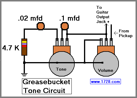 Note the INPUT (Yellow Wire) on most circuits comes in from the (lol im not sure what to call it) End Lug where you have it in the middle (what would make that end of the pot and the 100nF cap non-invoid [Same value both sides]) |
|
|
|
Post by JohnH on Oct 19, 2019 1:27:43 GMT -5
John, Regarding the Greasebucket on the circuit Angel and I are working on. I get tones on both sides of the pot. Of course, one darker than the other. If you look at my original drawing on the Concentric, you’ll see that it does look like it should be shorting out as Angel has said. Yet, it does not. I’m wondering if I leave it alone, or move it? ...and also replace the .022/4.7k with an 18k. Is that Greasebucket component of the circuit okay or not? I hope I’m making sense. I think, on this diagram, the yellow hot wire that is shown on the upper middle GB tone/volume lug, should go to the upper right lug instead |
|
|
|
Post by newey on Oct 19, 2019 6:06:53 GMT -5
potentiometer orientation (although I see my images for that are now history)It's the clockwise lug ("CW"), also usually designated as #3. The center lug, #2, (the moving part) is the "wiper", the other lugs are designated as clockwise and counterclockwise (or "anticlockwise", in Brit-speak). We also must designate, in wiring diagrams (but not in schematics) whether we are viewing the pots from the bottom up or from the top down (as if looking through the pickguard), since the right and left sides swap places depending on how they are viewed. Here, the ground wires make clear that we are looking at the bottoms of the pots. This is the typical way to draw diagrams since that is how one is views it while soldering it up.
|
|
|
|
Post by thetragichero on Oct 19, 2019 7:30:56 GMT -5
i have a little note card that translates schematic potentiometer to layout/wiring potentiometer (at least in reference tho a volume control). i can think a lot of things abstractly but realized long ago that that does not apply to potentiometers in my mind
|
|
|
|
Post by frets on Oct 19, 2019 13:11:09 GMT -5
Thanks John. And Trag...Thank you. But I am so visually literal that I can only comprehend what I’m trying to convey if they are upright and facing me. I easily can work from a regular upside diagram; however, every time I draw, it comes out facing me. You’re right and I’ll work on flipping them over.
|
|
|
|
Post by JohnH on Oct 19, 2019 18:04:19 GMT -5
I had a go at putting Angelbunnys tone circuit into GuitarFreak, it looks interesting:  I did it as drawn, except didn't have the 1M resistor available in the code. So I assumed that the Greasebucket circuit would be switched out since I couldn't model both at once. I think that having one or other but not both at once would be a good idea since togther they may make it too dark. Also, the midshaper looks like a nice thing to have available but you may not want it all the time since it is always cutting some output. The dashed line represents the tone with a vintage single coil like a CS69, and a standard tone control at max (or a GB at max), with 250k volume. The other lines switch off the standard tone and model the midshaper instead, with a range of settings on a 250k log pot from 0 to 10 on the knob |
|
|
|
Post by frets on Oct 19, 2019 18:27:15 GMT -5
This circuit was originally mine and fixed and improved by Angel. But I’m lost. The learning curve for reading this circuit in electrical engineering form is proving difficult. Above my pay grade. Not your worry; however, I really wanted the circuit to work as I had intended, if that was all possible. That goal was the ability to pull up on the push pull and have it provide an emulation of warmth. Not being a jerk - I just am lost. And I hope in a forum for sharing and help, that at some point, I’ll be able to understand. It’s frustrating...I’m trying desperately to decipher the schematic Angel was so helpful to fix.
|
|
|
|
Post by sumgai on Oct 19, 2019 23:38:18 GMT -5
frets,
I’m lost. The learning curve for reading this circuit in electrical engineering form is proving difficult. Above my pay grade. You obtain this level of knowledge one of two ways - either by paying BigBux to a college/university for a classic education, or you soak it up by the process of 'osmosis'. The latter takes a little longer, but doesn't cost nearly so much! The take-away is if you stick around, and/or if you visit other similar forums, you'll soon find yourself going "uh huh", "yeah I get that", and "aHA" much more often that your current number of such utterances per visit. Trust me on this, The NutzHouse is full of members who aren't Engineering school graduates.  HTH sumgai |
|
|
|
Post by perfboardpatcher on Oct 20, 2019 6:24:38 GMT -5
Frets, It seems to me that your intention is to make the switch on the ME pot switch between Grease bucket and Volume functionality. Then you need to use one pole of the switch as input and the other one as output. Input: middle lug connected to pickup selector switch out up lug: Grease Bucket down lug: Volume pot in Output: middle lug connected to output jack up lug: pickup selector switch out (=middle lug of input) down lug: Taper Volume pot Good luck with it! Compadres, I’ve tried this twice and the pull up does nothing. Does anyone see an error in the push pull wiring? |
|
|
|
Post by thetragichero on Oct 20, 2019 7:29:45 GMT -5
while not nearly as musical as a beauty school drop out, i eventually ended up doing that at engineering school (for various reasons), so most of my education on this kind of useful electronics has happened from reading online and working on projects
when i first came here i wanted layouts that i could follow
now i prefer schematics because i can see how everything works better
keep at it
|
|


 there ya go I got the Henry's wrong . Thanks John


