|
|
Post by frets on Jan 16, 2020 14:54:45 GMT -5
I am so sorry for your loss.
|
|
Deleted
Deleted Member
Posts: 0
Likes:
|
Post by Deleted on Jan 16, 2020 15:40:39 GMT -5
im sure if you have that circuit you will have a ONE of a KIND
|
|
|
|
Post by moogerfoogers on Jan 25, 2020 11:11:08 GMT -5
im sure if you have that circuit you will have a ONE of a KIND Quite possibly... But the real question is how useful will it be? Hoping this wiring will allow me to keep her by me in the studio without having to swap 3 different guitars out for quick demos. |
|
Deleted
Deleted Member
Posts: 0
Likes:
|
Post by Deleted on Jan 25, 2020 11:23:47 GMT -5
im sure if you have that circuit you will have a ONE of a KIND Quite possibly... But the real question is how useful will it be? Hoping this wiring will allow me to keep her by me in the studio without having to swap 3 different guitars out for quick demos.  i dont know .. i just design these things.. i can only say ITS WHAT Ya asked for to a degree i just hope you get the diagram how you like it .. sorry i dont have any good Graphics software to make them.. Im on Linux and limited a bit |
|
|
|
Post by newey on Jan 25, 2020 23:21:55 GMT -5
Moogerfoogers: I think I have correctly rendered 'bunny's schematic, but I make no guarantees that this is right. Don't start wiring this until it's checked! 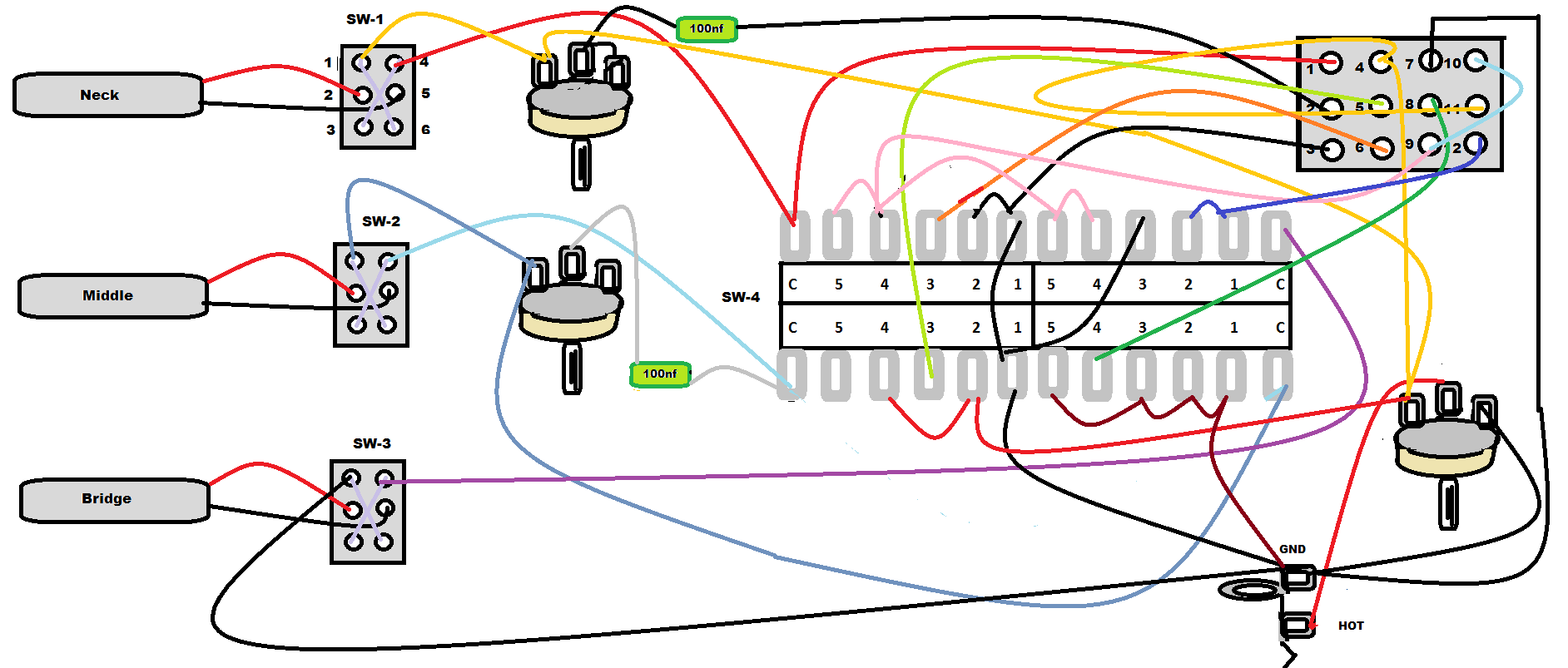 There is a lot of wire spaghetti, but there's no real good way to avoid that- that's why we like schematics . . . Note that I have omitted grounds for the pot backs, bridge ground, and so forth. I also showed all the grounds going to the jack sleeve, which is correct electrically, but is way too many wires to go to one lug. You should instead pick a grounding point, either backs of the pots or a star ground point. Also, a question for Ange1sbunny: Why do you show the neck tone pot wired on all 3 lugs? |
|
|
|
Post by moogerfoogers on Jan 26, 2020 1:19:14 GMT -5
THANK YOU!!! I'll wait for a checkup. Super excited!!!
|
|
|
|
Post by newey on Jan 26, 2020 7:36:04 GMT -5
You ought to tamp down your expectations. As has been pointed out earlier in this thread, this is a very complex scheme. My diagram could be wrong, and the error might not be spotted by a reviewer. Even if the diagram is correct, do not expect that this type of complex scheme will work "out of the box"- there will likely be some problems which will require troubleshooting. Often the troubleshooting process takes many times longer that it did to solder everything up in the first place. If this does check out and you begin wiring it up, go one step at a time and check your connections with a meter as you go along. Take notes as you go along, so you will know where you left off when you have to stop for a while and then pick it up again. Test all components before wiring them into the scheme. Since the 3 phase switches are identical for each pickup, I would start by doing those first, checking to be sure each one shows appropriate continuity, then proceeding from there. Using some sort of a template to mimic the pickguard or control cavity(I use cardboard), with holes to temporarily mount the components, is also a good strategy. In the end, you will have a complete wiring harness that can then be inserted into the guitar in finished form (after testing, of course). My point is that, it's good to be excited (that's what this site is all about!), but you should expect to suffer setbacks and frustrations along the way. IOW, leave the rose-colored glasses on your workbench . . .  |
|
Deleted
Deleted Member
Posts: 0
Likes:
|
Post by Deleted on Jan 26, 2020 18:22:26 GMT -5
Note that I have omitted grounds for the pot backs, bridge ground, and so forth. I also showed all the grounds going to the jack sleeve, which is correct electrically, but is way too many wires to go to one lug. You should instead pick a grounding point, either backs of the pots or a star ground point. Also, a question for Ange1sbunny: Why do you show the neck tone pot wired on all 3 lugs? Ya would be easier to do a STAR point on POTS (push pull have a Tag for Ground Point) Shouldnt matter Say LUG 1 Input .. LUG 2 Output (Arm) that travels along the Resistance Track, no matter where it is on the Track it shorts out LUG 3 , Connected or not When it does matter if you Cut the TRACK just before LUG 3 so that 0 will be OFF, as this was a part of the circuit to cut the Track, should just go from the LUG 2 (Arm)  |
|
|
|
Post by moogerfoogers on Jan 27, 2020 12:51:30 GMT -5
Going to wait for confirmation on the diagram. I’ll make a cardboard template in the meantime. I’ll do the star grounding also. I understand theres a big chance things might not work as expected from the start, but I’m willing to work through the gremlins & continue inform & and ask more questions once things start getting connected. Appreciate all the time & help here.. This community is amazing!!!
|
|
Deleted
Deleted Member
Posts: 0
Likes:
|
Post by Deleted on Jan 27, 2020 17:21:50 GMT -5
Sadly design takes time, you can't have one evil bunny ruling the world from behind the shadows controlling humans like the puppets they are >evil laughing time<
|
|
|
|
Post by newey on Jan 27, 2020 22:42:18 GMT -5
Well, but, in a sense, we do . . .  |
|
|
|
Post by moogerfoogers on Apr 6, 2020 11:19:21 GMT -5
It's been a while. I think I'm going to attempt the diagram that was posted above..
|
|
|
|
Post by newey on Apr 6, 2020 20:17:58 GMT -5
mooger- You have indeed been patient. And, I'm surprised no one has stepped up to the plate. But now that we're all shelterin' in place, maybe someone will have some excess time? IOW, I'm calling for "DIAGRAM CLEAN-UP IN AISLE 3!"  |
|


 i dont know .. i just design these things.. i can only say ITS WHAT Ya asked for to a degree


