|
|
Post by CheshireCat on May 2, 2006 2:58:09 GMT -5
Okay, I have a challenge. In my UUSS Mod, for various logistical reasons the Neck pickup is the last pickup in the chain, and is also, incidentally, a passive Duncan Lil'59, and is ergo much cheaper to phase invert than the Bridge pickup which is an 89. EMG's can't run backwards, so instead of paying $1 for a toggle, I'd need to pay $60 for an EMG-Pi2. Well, in addition to phase inverting, I want to be able to split it, or, more to the point, "half-phase" it, or "half-split" it, or whatever they are calling it these days. IOW, I want to be able to split off the trebles of one of the coils, while leaving the trebs on the other coil, so it would have the top end of a single coil but have the bottom end of a humbucker, which is a good solution for those humbuckers that just don't sound quite right when split. Well, here's the problem. If I run any series combination which uses the N pickup, and if I was to split the pickup, it would shunt the entire output from all the other pickups, and reground the N pickup on second coil, and I'd go from having ALL3 pickups in series to just having the one coil. Right now the stopgap solution is to do the pickup in parallel, with one coil half-phasing the trebles off and the full signal from the backend rolling thru clean and unshunted thru the other coil. The question, is there a way to do this in series. Second, is there a way to do phase inversion where I can reorient the coils to maintain the solution for the splitting challenge? Chesh BTW - Right now I have a solution for this in parallel, but I fine myself leaning towards series. |
|
|
|
Post by CheshireCat on May 2, 2006 4:13:58 GMT -5
Okay, new wrinkle:
I thought of a possible adjunct as a solution. If I have the full humbucker, then it would be straight series, but if I did the split or half-phase, then that coil would go to the front of the line, and feed the B pickup, thus starting the chain. That way, I get the additional coloration of the half-phased coil, only without the possibility of shunting of the rest of the pickup chain.
Another possibility would be treating the splitter like a true bypass for that coil. Of course, I would still want to phase invert, and half-phase (half-split, whatever).
Any ideas?
(Oh, and this needs to be accomplished with only two switches, the splitter and the phase inverter.)
Chesh
|
|
|
|
Post by jhng on May 2, 2006 4:32:34 GMT -5
If you do the "half-split" by putting a capacitor across just one coil of the humbucker (so it is connected between (e.g.) the ground of the HB and the coil-split wire), rather than by connecting it to the star ground, that should work in series and parallel combos. No?
Hastings
|
|
|
|
Post by CheshireCat on May 2, 2006 17:34:23 GMT -5
If you do the "half-split" by putting a capacitor across just one coil of the humbucker (so it is connected between (e.g.) the ground of the HB and the coil-split wire), rather than by connecting it to the star ground, that should work in series and parallel combos. No? Hastings Not if I also phase invert. Also, how do I split or half-phase the front coil without shunting out the entire signal of the other two pickups (or half-phase them) when doing ALL3 in series (or any other series combo with the N pickup)? Also, what do you guys think? How much difference would you think there would be between the N pickup coils in series, or parallel. I have a solution in parallel, but I'm debating doing it in series, because I'd like more of a edge in the neck position. Chesh |
|
|
|
Post by Mike Richardson on May 2, 2006 19:38:46 GMT -5
You're running EMGs and passives IN SERIES?? The 89 is NOT a humbucker that you can "split". It is TWO SEPARATE PICKUPS in one housing. You have a standard SA stack on one side and an 85 on the other. 89s don't coil-tap.
|
|
|
|
Post by CheshireCat on May 2, 2006 21:21:08 GMT -5
You're running EMGs and passives IN SERIES?? The 89 is NOT a humbucker that you can "split". It is TWO SEPARATE PICKUPS in one housing. You have a standard SA stack on one side and an 85 on the other. 89s don't coil-tap. Yes, I know. And to that end, I'm not following your point. The 89 is the first in the chain. I'm not "splitting" it. I'm using the standard switching convention to switch between the dual modes. I simply used the nomenclatured shorthand of "splitter" in refering to this switch because that's an easier concept to grasp for most who are not in the know. "Dual mode switcher" or something of the sort is quite a mouthful and doesn't mean much to people not in the know. Incidentally, yes, I'm mixing passives and actives. And, contrary to popular belief, they can be mixed . . . if you use the proper buffering, or preamping, which I am also using. I'm a very big advocate of that (using the proper buffering, that is). Chesh |
|
|
|
Post by Mike Richardson on May 2, 2006 22:17:24 GMT -5
Well, if you're mixing them in parallel, it's a simple matter of using the proper volume pot value for each, unless you're preamping the Duncan to get low-z operation, in which case the EMG values will work for both. I'm still not clear on the series operation, though. Are you going EMG-Duncan-PA2 or something like that? I'm not quite clear on your "signal chain".
|
|
|
|
Post by CheshireCat on May 2, 2006 23:54:16 GMT -5
Well, if you're mixing them in parallel, it's a simple matter of using the proper volume pot value for each, unless you're preamping the Duncan to get low-z operation, in which case the EMG values will work for both. I'm still not clear on the series operation, though. Are you going EMG-Duncan-PA2 or something like that? I'm not quite clear on your "signal chain". Mod= UUSS; N = Franken'59; M = Antq Tele; B = 89. All pups run to a properly rated trimpot before continuing. The 89, being at the beginning of the chain, would feed the passives in the cases where series is involved. Of course, that's not including any additional buffering that might be needed. I was going to go with a non-toggled PA2, which is supposedly available, but I'm having bugger'ell trying to get my hands on one. So, instead, I'll either make my own or get another version which I saw another company sell. |
|
|
|
Post by Mike Richardson on May 3, 2006 5:47:52 GMT -5
Don't know how hard it would be, but you could look into getting a normal PA2 and just remove the switch. Replace it with a jumper (in the right place, naturally), and you're done. I've replaced EMG pots before, but never a switch.
|
|
|
|
Post by jhng on May 3, 2006 6:04:44 GMT -5
Chesh, Sorry. I think the vagueness demon got me. What I mean is that if you wire the cap according to scheme A, rather than B, below it should work fine. All it does is short out "Neck coil 2" above a certain frequency. 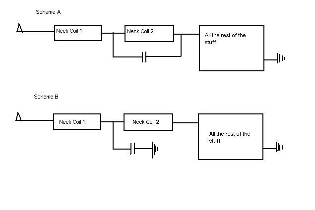 |
|
|
|
Post by CheshireCat on May 4, 2006 4:57:01 GMT -5
All it does is short out "Neck coil 2" above a certain frequency. Would the rest of the signal from the other pickups above that certain frequency go with it? |
|
|
|
Post by Mike Richardson on May 4, 2006 5:49:00 GMT -5
It puts a sort of "notch" in the frequency response. You could switch it from around the second pickup to around the first or third, and it will change the sound.
|
|
|
|
Post by jhng on May 4, 2006 6:12:37 GMT -5
The signal from all the other pickups is totally intact in Scheme A, but would lose it's top end in Scheme B.
|
|
|
|
Post by UnklMickey on May 4, 2006 12:00:46 GMT -5
IMHA (assessment), in Scheme A, the highs from neck coil 2 would be attenuated by the cap. the highs from all OTHER coils would be increased by having the cap.
Scheme B is probably bad idea.
|
|
|
|
Post by CheshireCat on May 4, 2006 12:44:56 GMT -5
IMHA (assessment), in Scheme A, the highs from neck coil 2 would be attenuated by the cap. the highs from all OTHER coils would be increased by having the cap. What other coils and how so? |
|
|
|
Post by ChrisK on May 4, 2006 14:49:04 GMT -5
unk,
I absolutely/empirically agree. The Fender S-1 schemes add the "special capacitor" (I don't know how special it really is, but it does appear to be a capacitor) across one of the two pickups configured in series.
In my padouk Strat copy in the gallery, which used the original Mike Richardson scheme, I placed a push-pull (for phase) pot (for hi-cut tone) one each directly across the bridge and neck pickups.
In parallel, things are quite normal. In series, when the tone is dialed towards "0" (CCW), the affected pickup is high freq muted while the other(s) has its highs enhanced. Since the middle pickup in this guitar is the brightest, it is pronounced.
I'm using a 0.022 uF cap/500 K pot for each.
Scheme B is a tad convoluted in that the cap enhances the highs of all coils "above" it, while cutting the highs of all of those "below" it (directionally relative speaking).
|
|
|
|
Post by UnklMickey on May 4, 2006 16:31:21 GMT -5
"I absolutely/empirically agree."
i can only imagine the smile on JohnH's face right now!
Chesh,
here's one way to look at this, from a circuit analysis point-of-view, which i might add, is ALMOST as valuable as ChrisK's empirical results.
since higher frequencies "pass" more easily through a cap, those being generated by the coil in parallel with the cap (neck coil 2, in this case) are being attenuated.
however the high frequencies generated by any coils in series with neck coil 2, will have an additional path around the inductance and resistance of neck coil 2.
so the high frequecies generated by those coils will now pass more easily, than if the cap were not present.
unk
|
|
|
|
Post by CheshireCat on May 4, 2006 18:26:55 GMT -5
here's one way to look at this, from a circuit analysis point-of-view, which i might add, is ALMOST as valuable as ChrisK's empirical results. since higher frequencies "pass" more easily through a cap, those being generated by the coil in parallel with the cap (neck coil 2, in this case) are being attenuated. however the high frequencies generated by any coils in series with neck coil 2, will have an additional path around the inductance and resistance of neck coil 2. so the high frequecies generated by those coils will now pass more easily, than if the cap were not present. unk So, you're saying that instead of shunting off the trebs from the M and B pickups, when piped via series thru the N pickup, the trebs will actually be beefed up, and not shunted!?! |
|
|
|
Post by Mike Richardson on May 4, 2006 18:35:26 GMT -5
It's not so much a "treble boost" as a "low cut".
|
|
|
|
Post by CheshireCat on May 4, 2006 19:11:00 GMT -5
It's not so much a "treble boost" as a "low cut". Explain. |
|
|
|
Post by jhng on May 5, 2006 4:05:15 GMT -5
Scheme B is probably bad idea. I put Scheme B in to show the distinction. I wouldn't suggest actually wiring it like that! Scheme B is also just the kind of thing that can result in odd and unforeseen out of phase sounds if you don't think through all aspects of the wiring very carefully. Whereas Scheme A is pretty fool-proof. Hastings |
|
|
|
Post by sumgai on May 5, 2006 4:05:21 GMT -5
Chesh, unk and Mike have analyzed the action of Scheme A correctly. It was an unfortunate, but common, choice of words on unk's part to say "the highs from all OTHER coils would be increased". Yes, they will be stronger, by comparison to the lows, but they won't actually be increased in raw strength. (There're no active components!) Mike re-iterated that idea by saying that the circuit was a "low cut" one. This is because the capacitor will tend to allow signal to flow freely above a certain frequency, and tend to restrict, or cut, signal flow below that frequency. The magic frequency, as you probably already knew, is dependent on the value of the coil's inductance. The coil works in the exact opposite manner, allowing low frequencies and restricting high frequencies. The interaction of the two components is such that at some point, the capacitor is going to have more persuasion over the signal than the coil, giving the net effect of the lower frequencies being cut back overall. In turn, that will make the treble part of the signal appear stronger. But not boosted.  HTH sumgai |
|
|
|
Post by CheshireCat on May 5, 2006 6:35:38 GMT -5
Chesh, unk and Mike have analyzed the action of Scheme A correctly. It was an unfortunate, but common, choice of words on unk's part to say "the highs from all OTHER coils would be increased". Yes, they will be stronger, by comparison to the lows, but they won't actually be increased in raw strength. (There're no active components!) Mike re-iterated that idea by saying that the circuit was a "low cut" one. This is because the capacitor will tend to allow signal to flow freely above a certain frequency, and tend to restrict, or cut, signal flow below that frequency. The magic frequency, as you probably already knew, is dependent on the value of the coil's inductance. The coil works in the exact opposite manner, allowing low frequencies and restricting high frequencies. The interaction of the two components is such that at some point, the capacitor is going to have more persuasion over the signal than the coil, giving the net effect of the lower frequencies being cut back overall. In turn, that will make the treble part of the signal appear stronger. But not boosted. So, take this from the top. If I have ALL3 in series, starting with the B pickup feeding into the M pickup, both of which in turn feeding into the N pickup, and I have the half-phaser selected for the N pickup, exactly what will happen? I ask because, among other reasons, I specifically left the splitters, half-phasers, and phaser inverters out of the UUSS because at the time they were adjuncts to what was a maximization of combo options from a SuperSwitch and S-1 Switch, recovery the lost combos and such, but now it's getting to the point where the splitters, half-phasers, phase inverters, and so on, are becoming an integral part of the switching schematic, and to that end I'm very interested in expanding it. Chesh |
|
|
|
Post by Mike Richardson on May 5, 2006 7:47:19 GMT -5
That's how the tone controls on my original setup work when the pickups are in series, for whatever that's worth.
|
|
|
|
Post by sumgai on May 5, 2006 11:24:19 GMT -5
Chesh, The net effect will be, in theory, that the N pup's trebles are cut, and the M & B lows are cut. I say in theory, because all of this action is the result of complicated math involving the interaction of the inductance and capacitance of N + cap, and the interaction of *that* in series with the inductance of M and B. (Whew!) Nothing we can't work out, if needed, but do we really want to get that deep into this? I can if you wish, but I'd probably botch the explanation.  There are many sites on the web that can say this better, and also show the math to go along with it, but the short and sweet of it all is, the values of the coils and capacitor are going to have a great effect on the exact frequency whereupon all of this takes place. Another aside: if you haven't heard this term already, it's now time to bring it up.... we call the point in a curve where the action starts "the knee" of the curve. Think of looking at your leg from the right side, from hip to floor. If you are sitting down, the "treble cut" curve will look just like your leg. Easy to remember now, right?  If we choose a cap value carefully, because we can't always choose the inductance value of our pickups, then we can pretty much place the knee at the precise frequency we wish. We can even make it sharper (more rapid fall-off) or less sharp, but there is a finite limit to how gentle the slope can be. IOW, there is a minimum sharpness, but I'm getting too technical here.  Like you, I have chosen (so far) to not use any kind of half-phase system to further modify my available tones. At this point in time, I foresee that if we keep introducing small tidbits of possible tone modification, we'll soon run out of possible analog control methods, and will have to resort to digital control. Hey, I'm up for that!  Did this help? sumgai |
|
|
|
Post by UnklMickey on May 5, 2006 11:29:05 GMT -5
....So, take this from the top. If I have ALL3 in series, starting with the B pickup feeding into the M pickup, both of which in turn feeding into the N pickup, and I have the half-phaser selected for the N pickup, exactly what will happen?... Chesh, it seems like Hastings, Sumgai, Mike, and I are all saying about the same thing, but using different words to describe what would happen. ChrisK's real world test supports the theory and analysis. you used the expression "take this from the top", but to make sure we're all still on the same page here, when you describe the series connections, are you taking that from the bottom? meaning: the bridge has a connection to ground, the middle is stacked on top of that, and the neck on top of the middle? if so, then Hastings's drawing applies: i51.photobucket.com/albums/f373/jhng/jhng_half-split.jpgHastings described verbally in his first post his solution, which is represented in Scheme A. of the drawing he later posted. i was totally on-board with his verbal description in his first reply, but the drawing makes it so much easier to discuss. (BTW: +1 for posting that drawing!) when i remarked that Scheme B was probably a bad idea, i was simply re-iterating what Hastings has already implied. using his drawing, the bridge and middle are "All the rest of the stuff". in a pure series path, the inductances of all the coils add. this causes a "darkening" of the tone. the "trebs" from any one coil have to pass through ALL the other coils to get to the output. in Scheme A, the trebs from neck coil 2 get shunted by the capacitor, so they never make it to the output. so the trebs from neck coil 2 are reduced. so what about the trebs that are generated by neck coil 1 ? the go to the output, return through ground, travel through "All the other stuff", and are shunted THROUGH THE CAP bypassing neck coil 2, on their way back to the "bottom" of neck coil 1. that means that the trebs from neck coil 1, had an easier path (one less inductor) than they would have had, without the cap. so relative to not having the cap, the trebs are "boosted". or, to put it in other terms: they go through one less low pass filter. the same can be said for any other coil in series with a bypassed coil. so to make a short story long, the treble content generated by a bypassed coil will be reduced. the treble content generated by a coil in series with a bypassed coil will be increased (relative to having the same circuit minus the cap). so why is Scheme B a bad idea? the treble content from neck coil 2 and "All the other stuff" is being shunted by the cap. none of those contributions are being seen at the output. the trebs from neck coil 1 will have a much easier path to the output, because the inductances of all other coils are being bypassed! however, how much treble content do we have to begin with, being generated by neck coil 1? not nearly as much as would be generated by the bridge or even the middle. so we're giving all that away, and getting lots more of the small amount we generate at neck coil 1. sounds like a weak trade to me. unk |
|
|
|
Post by jhng on May 5, 2006 11:52:36 GMT -5
Unk -Thanks for the kind words!
It's a pretty fiddly concept to get a grip on even with a diagram.
It occurs to me that if you could bring inductors (in addition to the pups!) as well as capacitors into play, you could potentially construct systems where you have (e.g) the bottom end of the Neck pup combined with the top end of the Bridge pup.
That would be interesting....
Hastings
|
|
|
|
Post by UnklMickey on May 8, 2006 11:46:17 GMT -5
Hastings,
fiddly concept it is.
since the pickups are primarily inductors, the bypass cap already does quite a bit in terms of getting you bottom from the bypassed coil (or you could put it across a whole HB) and treble from the non-bypassed pup when they are in series.
adding an inductor to the scheme might be even more interesting.
unk
|
|
|
|
Post by CheshireCat on May 11, 2006 1:59:44 GMT -5
Quick update: I'm not doing any half-phasing. I just tested the single coil in context to orienting the magnet correctly before I epoxy it in place (which I just did) and noticed that it sounds great as a single coil, and doesn't need to have the other coil half-phased in to beef it up, tho I'm sure that's a good idea for other buckers that can't pull off a split real well. Carry on. |
|


 There are many sites on the web that can say this better, and also show the math to go along with it, but the short and sweet of it all is, the values of the coils and capacitor are going to have a great effect on the exact frequency whereupon all of this takes place.

