djhollowman
Apprentice Shielder
 7 outta 6 cats preferred it.....
Posts: 29
Likes: 0
|
Post by djhollowman on May 9, 2006 16:02:47 GMT -5
Sorry, I know I have this posted elsewhere, but I'm slightly in a hurry to finish this guitar as my wife is now 3 days over her due date, and I know I won't get any guitar-type stuff done once baba arrives! 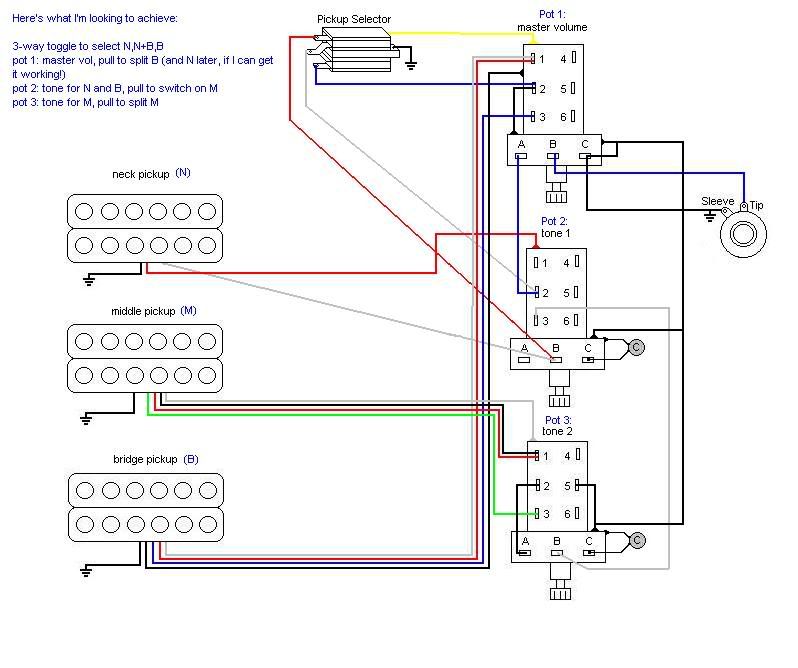 I've wired the guitar as described above already, but it isn't behaving as expected! Pot 2 doesn't change the tone at all, and the coil-split in pot 1 seems to work the wrong way (when switched to humb it sounds weaker, but I don't think it sounds like a single either cos it sounds hum-cancelling...strange...). The neck pickup sounds louder on its own than when it is selected along with the bridge. Pulling pot 2 to switch on M makes it all sound slightly quieter, when I would have expected more noise, especially when I have M in humbucking mode! Can anyone please guide me here? Many thanks! |
|
|
|
Post by UnklMickey on May 9, 2006 17:38:27 GMT -5
i've made a print and i'll take it home with me tonight.
i won't be able to get back to you until tomorrow.
i sure hope one of the other guys will be able to look this over before then.
unk
|
|
djhollowman
Apprentice Shielder
7 outta 6 cats preferred it.....
Posts: 29
Likes: 0
|
Post by djhollowman on May 10, 2006 1:56:00 GMT -5
Thank you Unk!
|
|
|
|
Post by sumgai on May 10, 2006 3:23:59 GMT -5
Derek, I don't know what happened, but it's beginning to look like the forum threw away my reply of a few hours ago. If that ever happens again.......  So, if I can salvage any of it from memory..... I think I see a couple of potential trouble spots. The lower terminal of the pup selector switch (blue) looks like it's going to ground via lug 2 on the master pot push/pull switch. And if that's the case, then I can't see how the bridge pup ever gets connected to the output. While we're looking at the pup selector, what's the yellow wire for? Also, the tone pot for Neck and Bridge has no visible connection for the bridge pup. And finally, just for the short course, the pickup wiring could use a bit more clarity. The colors are used differently from one pup to the next, so things like + and - would help. That's it for now, and good luck on that new tax deduction! sumgai |
|
|
|
Post by UnklMickey on May 10, 2006 13:00:15 GMT -5
hey Sumgai,
thanks for popping in.
i'm falling a bit behind on things, so i'm sure DJ will appreciate you having looked at this.
apparently "the server ate my homework" was going around last night!
i modified my post and asked DJ what make and model the pups were, but that doesn't seem to have taken.
it will be even more useful if he can indiate which leads are + and -, but you must admit,
we get quite a bit of request on this board for help with problems that are this complicated, with no drawing at all.
so in that respect, even having drawing is a big step forward.
i'll look over the drawing and see if i can find any other potential trouble spots.
thanks again Sumgai.
unk
|
|
djhollowman
Apprentice Shielder
7 outta 6 cats preferred it.....
Posts: 29
Likes: 0
|
Post by djhollowman on May 10, 2006 15:37:30 GMT -5
Right chaps! Thank you for your input. I believe I've nearly cracked it! Here's the revised diagram: 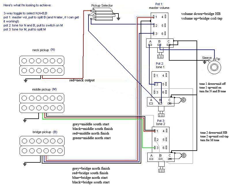 The only thing I'm unsure of now is how to do the coil-taps! This will answer all the questions about wiring colours and pickup makes. The bridge is a Charvel, has 4 conductors, red and black make a circuit, and blue and white make a circuit - that's all I know about it! Argh! The middle and neck pickups are unbranded generic ones. The middle one also has 4 conductors, green and red make a circuit, and white and black make a circuit. Please note - I have based the coil-tap wiring in the picture based on assuming my knowledge of coil-tapping to be correct! Namely, that you take the north finish and south finish wires together, put them to one side of the switch, and the north start to the other side, with the middle of the switch becoming the "new" output (to the selector/vol pot) - IS THIS CORRECT?? What would be the consequences of having the starts and finishes the wrong way round - phase reversal?? I would desperately like to know how to work out which wires are + and which are - !! I have no idea! I assumed it to be an earth, it appears to connect to the side of the switch casing, but there's also a bare earth braid present. Any ideas?? Think I've sorted that. Ditto This is my first go at doing a wiring drawing, well, second since it's an edit! I did it in MS Paint - limited, but more noob-friendly than Photoshop! Still, it does the job well enough of graphically representing something you'd otherwise find difficult to convey, I feel! Anyway, I did the drawing using exactly the same colours as the pickups etc are, so that it would be more relevant to me. As mentioned above, I'd love to find out the polarity of each wire, and that would make it easier for us all! Please bear in mind that I'm assuming the coil-tap connections based on my (limited) knowledge of how pickups work! You get tax deductions for having anklebiters?? Not in Scotland! It'll mean I get a wee bit more tax credit from the government. Thank you for the kind thought however! (She's still not even showing any signs of imminent labour! 4 days overdue...) My thanks to you all. Derek |
|
|
|
Post by UnklMickey on May 10, 2006 19:01:58 GMT -5
"What would be the consequences of having the starts and finishes the wrong way round - phase reversal?? I would desperately like to know how to work out which wires are + and which are - !!" you are probably experiencing the consequences already. 2 coils or pickups that are OoP (out of phase) sound "thin". the treble is mostly intact, but the bottom is completely decimated. also, if a HB is wired OoP, the hum-canceling doesn't happen. the most important thing you would want to do, after determining which leads connect to which coils, is to determine the + and - of the coils. connect a meter to the leads of a coil. if the voltage goes positive when the tip of a screwdriver is allowed to touch a pole-piece, and negative when the screwdriver is pulled away, mark the lead that's connected to the + (red) probe of the meter as positive. do this for each and every coil. keep track of the colors for each pickup. next determine the magnetic polarity of each coil. you don't have to know whether it's north or south. just which ones are the same, and which ones are opposite. use a small magnet, and pick one coil as a reference. we'll call the polarity of that coil, "A". note the orientation of the magnet when it attaches itself to the pole-pieces on the front of the coil. if it has the same orientation, when attached to the front of another coil, also mark that coil as "A" polarity. if it flips, mark that coil as "B" knowing the magnetic polarity is not important when using HBs as HBs. but if you SPLIT them, and have an "A" coil from one, and a "B" coil from another, you can still have hum-canceling when the coils are electrically in phase. if you want to put 2 split HBs OoP, using both "A" coils or both "B" coil, will maintain hum-canceling. yeah, i know, i've gone completely verbose again. but if you pay attention to the finer points, you can get a better product. hope that helps, unk |
|
|
|
Post by sumgai on May 12, 2006 2:47:21 GMT -5
Derek, Your new diagram looks correct now, good job.  As for the phasing of each coil on those HB's, I think unk has given a pretty lesson on how to do all of that, so I won't try to add anything, I'd just muck it all up.  Tax credits?! You get a credit for having a kid? We're lucky they don't make us pay them more just because we have a kid in the first place!! And if she's this far along with no signs, then the original estimate was off. After all, it was just an estimate, not an iron-clad guarantee.  sumgai |
|
djhollowman
Apprentice Shielder
7 outta 6 cats preferred it.....
Posts: 29
Likes: 0
|
Post by djhollowman on May 12, 2006 6:13:13 GMT -5
Excellent replies, thank you thank you!
What about when you're using covered pickups (as I am here)?
My latest son was born yesterday morning! Yay!
Will work on this again when I get a chance! Those of you with kids will know what I mean!
Thanks again guys!
DJ
|
|
|
|
Post by UnklMickey on May 12, 2006 10:06:26 GMT -5
... What about when you're using covered pickups (as I am here)?... DANG!..............it's always sumthing! you will probably be able to do the same thing, by allowing the tip to touch the cover above where the pole-pieces are. i think the voltage will be less, but still enough to tell the polarity. if not, determine the polarity of the coil who's pole-pieces you CAN touch. then switch the meter to AC volts. bring the pup near a wall-wart or other source of hum. record the voltage. put the two coils in series. measure the voltage again. if it stayed about the same or went up slightly, this is not the correct wiring. flip the wires of one of the coils. if the voltage is now much, much lower, you have the correct polarity. the two wires that are connected together, are opposite. so if the wire that was + on the screw coil, was connected to the unknown wire from the slug coil, when the hum is reduced, it means the unknown wire from the slug coil is - . yikes, that was the long-way-round, don't you think? hey, enough of this wiring stuff. looks like it's time to start shopping for a mini-strat. congratulations unk |
|
|
|
Post by sumgai on May 12, 2006 14:53:40 GMT -5
Derek, Congrats!  to you! I just called my broker and put in an order to buy more stock in Novartis, the makers of No Doz - you're gonna be making me rich, man, because you're about to start buying this stuff by the case! ;D sumgai |
|