|
|
Post by ms on Apr 19, 2024 6:55:28 GMT -5
The green line in the first plot below shows the real part of the pickup impedance of an SD SH1N, with the effect of the coil capacitance removed. It rises with frequency as a result of eddy currents in metal parts, especially the cores. The magenta curve shows the imaginary part; its downward curve indicates an apparent fall in coil inductance with increasing frequency. Both of these effects can be the result of resistance in parallel with the coil, as we will see. In a pickup this can come from the mutual coupling to metal parts, which act like secondaries of a very poor transformer. The load from a transformer secondary appears in parallel with the primary. The effect of eddy currents has dependence on frequency; for example, the resistance must be infinity at DC.  Look at the impedance of a very simple model, shown below, just an L with both a series and parallel resistor (frequency independent). The colors match those in the plot above with values listed in the title. It is remarkable how close this is to the measurement above. It reproduces all the major features, but the shapes of the curves are not right. Next I will try to improve it, making the parallel resistance dependent on frequency (as we expect in the actual case).  |
|
|
|
Post by ms on Mar 16, 2024 17:57:34 GMT -5
Before proceeding, let's look at the test results from a humbucker, measured the same way as the pickup/cancellation coil. i went looking around for a humbucker, and the first one I found is a Seymour Duncan Jazz neck (SN2n). The first plot is the measurement from one coil. The second is for the two coils in series, that is, hum-canceled. The actual signal output is about 6 db more than that of one coil, and so six db must be added to the db differences on the two plots to get the degree of cancellation. The pickup parameters are 3.722 H, 7.21 K at 100 Hz. The individual coils are 1.6226 H at 3.54 K and 1.6208 H at 3.67 K. This is remarkably well matched in inductance, although this is achievable with careful turns counting. The resistance measurements are not so close since it is not possible to wind two coils in exactly the same way, even if the turns counts are the same. Also achieving such close inductances requires careful matching of the slugs and screws; that is materials and lengths must be carefully selected. So, given such good matching, how good is the cancellation?  
It looks like we have a bit less than 50 db of hum reduction at 170 Hz, and significant reduction over the whole useful signal bandwidth (about 5 KHz). A very well engineered and manufactured pickup! |
|
|
|
Post by ms on Mar 14, 2024 13:56:36 GMT -5
The wavelength dependency makes the frequencies inharmonic so that the overall shape of the composite wave changes with time. And non-linearity in the signal chain could make this important. |
|
|
|
Post by ms on Mar 14, 2024 13:54:48 GMT -5
If I understand this right, then you could argue that the steel pieces between the magnets guide flux from the vibrating string to the bottom of the extra deep bobbin. But it would appear that the sound of a humbucker is not strongly determined by the two sampling regions as the more than half century old pickup myth states. This paper seems to go into some detail on that question, but from what I can tell the aperture for single coil versus humbucker seems to be a bit of an assumption here? till.com/articles/PickupResponse/index.htmlRight, it is not the width of the pickup, as he says. But beyond that, whether the sampling window is 4 mm or 17 mm just does not make that much difference. Too much larger than that, though, and you will see a significant loss of higher harmonics, especially on E6. |
|
|
|
Post by ms on Mar 14, 2024 11:22:42 GMT -5
I looked some more and was able to find confirmation from PRS that the NF DD pickups do actually use magnetic pole pieces: "The new Narrowfield DD’s continue PRS’s proprietary Narrowfield pickup platform, but trade the Narrowfield’s traditional stairstep design for a mixed magnet/steel pole piece design and a slightly deeper bobbin" If I understand this right, then you could argue that the steel pieces between the magnets guide flux from the vibrating string to the bottom of the extra deep bobbin. But it would appear that the sound of a humbucker is not strongly determined by the two sampling regions as the more than half century old pickup myth states. |
|
|
|
Post by ms on Mar 14, 2024 11:14:43 GMT -5
On reflection, I think that the truth of the matter is that because the wave velocity increases with frequency, the wavelengths of the upper harmonics are not exact submultiples of the fundamental wavelength and don't fit exactly into the string length so the simple static pattern is never quite established until the upper harmonics have decayed.
The wavelengths of the harmonics are determined by the length of the string, and then the frequencies are a function of this length. You can measure the frequencies of the harmonics, and you will find that they are not exact multiples of the fundamental. Or, another way to say it: in the string vibration problem, the geometry of the system is input, and the frequencies of vibration are output. |
|
|
|
Post by ms on Mar 13, 2024 13:25:25 GMT -5
So here is the circuit from the previous post with the adjustment network in place. 
The first common sense thing to do is to get rid high frequencies from the cancellation coil that you do not need. Maybe they can cause trouble. Ch dos this; the value was chosen while recognizing that it might have some effect at frequencies we care about, but also recognizing that the other vales we choose will take the into account. The next thing to do is to get the low frequency cancellation working as well as possible with the resistor Ra. In this case the unadjusted correction voltage is a bit high, and so we a reduce it with one resistor. If it were a bit low, a slightly more complicated network would be necessary. The variable resistor for Ra is left in the circuit since a small readjustment might be necessary after the next step. It is surprising that even as low as 170 Hz there is a phase error. We know it is phase because we can measure the magnitudes of the pickup and cancellation coil voltages, noting that their difference is less than the measured residual. I suspect that this caused by eddy currents excited in the pole screws excited by the test B field. In any case Cp shifts the phase and improves the cancellation at 170 Hz. It also hurts the cancellation at higher frequencies, but this can be improved by Rs. |
|
|
|
Post by ms on Mar 12, 2024 13:42:47 GMT -5
So if you believe this test, (as I do), then you should get close to a tele lead or strat sound without the hum by making humbuckers in this way:
1. Use fewer turns on each coil so that the inductance of two in series is what you want. Since inductance decreases faster than linearly with turns, you do not need to take off that many.
2. Use Alnico rod magnets for the right Q.
3. Do not use a tall Bobbin; the turns near the bottom do not contribute much to the level. So the turns you lose with respect to a strat pickup to get the right inductance cost you less level than you might think in terms of output if you are used to strat pickups with tall bobbins.
4. Lose the baseplate? Not sure; a nickel silver base plate kills some highs, but not that much. The cores are more important.
Has anyone done something like this?
|
|
|
|
Post by ms on Mar 12, 2024 12:47:58 GMT -5
So now it is time to understand how a cancellation coil in series with a pickup works. I do not yet understand all the details, but enough to do a good job. The top part of the figure below illustrates a simplifying principle: if you only have impedances in series with the noise voltage sources, then achieving cancellation does not depend on what those impedances are or their relative values, nor on the load impedance. Of course, we want the impedances in series with the cancellation coil to be low value compared the in the pickup since we do not want to influence the sound. So what do you do if you have a coil capacitance that goes across the pickup, as shown in the bottom part of the figure? This is a situation where you can find the Thevenin equivalent, where for analysis, you replace the network you have with another that consists of a voltage source, Vth, that depends on the elements in the circuit, in series with an impedance, Zth, that also depends on the elements in the circuit. So then you have to find circuit element for the cancellation circuit such that when they are put in the circuit, its Thevenin equivalent voltage is the same as that of the pickup, that is, same magnitude versus frequency, but opposite phase. It is not assured that this is possible in all cases, but you certainly can do a good approximate job if you only need good results over a limited frequency range. In fact, you do not have to do any actual analysis. You can examine the circuit, do some arithmetic, and try things until you get something that works well enough. Later, we look at the result of this process.  |
|
|
|
Post by ms on Mar 12, 2024 12:20:15 GMT -5
Side note: Impedance is moot if you have an active preamplifier and a mixer for both the pickup and balance coil. Because then, there's no need to put them in series or parallel combination that would introduce the need for an undesired pickup impedance or some unwieldy passive compensation. Also the set input gain to the mixer, would dramatically loosen constraints on the balance coil.
I do fully understand the desire to avoid active electronics in a guitar.
I devised a "half active technique" quite a while ago, where the cancellation coil goes to the input of a source follower, and the pickups are removed from ground and connected to the output of the source follower. The cancellation coil is just another pickup, but you should make it very slightly more sensitive. I suppose that you could argue that once you have introduced active electronics into the guitar, you might as well go all the way put a preamp on the pickups as well. But you could also argue that the source follower can be low current for long battery life, and when the battery goes dead, the guitar still works, and all you lose is hum cancellation. |
|
|
|
Post by ms on Mar 12, 2024 11:45:28 GMT -5
The comb filtering due to adding two pickups is usually shown as continuing right up to the highest harmonics. The impulse response of such a filter would be two time spaced identical impulses for one input pulse. That may nearly be true for a humbucker pole spacing but we know that the travel of the wave on the string is dispersive, i.e. the impulse changes shape as it travels. So the two output pulses in the impulse response will have different shapes. The pure cancellation at short wavelengths seems unlikely.
Another factor I forgot about, if we're talking about higher frequency harmonics, they don't last long after the transient. So if you say the comb filtering only effects higher harmonics, then it will be limited to a "pick attack" modification of the sound. I think low harmonics are definitely filtered as the math describes, because you can fake the sound of "notch positions" with a graphic EQ by copying the comb filter, but not only that, if not for the comb filtering, the notch positions would sound more like a true blend of constituent pickup signals. I think he is saying that the comb filtering resulting from two pickups (say neck and bridge) works for low harmonics, but not for higher ones because of a kind of "blurring" resulting from dispersion. ("Blurring" might not be a great description, but it is all I can think of now.) But your decay time argument is right. At a high enough harmonic, or frequency, the pattern is never set up because the energy is gone before enough round trips can occur. But as long as the energy is there, I think it does. A given string harmonic corresponds to a very narrow frequency range, and so there is a well defined phase velocity. |
|
|
|
Post by ms on Mar 12, 2024 10:40:13 GMT -5
Since the result of this experiment is that there is an audible but not large effect, it proves the point even if the equivalence were not exact to the actual case. That is, it would be very hard to believe that some small difference between this test and the actual effect could make a large difference in the sound.
|
|
|
|
Post by ms on Mar 12, 2024 6:03:49 GMT -5
8 ==> 10
If the "in between" pieces are not magnetized, you need take into account the possibility of decrease in volume with string bends. So there might be more to the design than meets the eye. These are taller, thinner bobbins, and so I guess that you need lots of steel to make sure that the windings furthest from the strings are effective (unlike the Alnico in Fender SC, which allows field to escape).
|
|
|
|
Post by ms on Mar 9, 2024 15:45:50 GMT -5
The pure cancellation at short wavelengths seems unlikely. Yes, the instrument would be frustrating to play if that were so. Because of the fretting in different places, notes would have effectively arbitrary volume. I think it's reasonable to believe that the effect exists, but is diffuse due to the phase spreading that you mentioned. In other words, affects all notes almost equally (with a gradation from very low to very high). Tillman's diagrams show the behaviour of an extremely simplified mathematical model. The short wavelengths are a very small fraction of the energy of the string vibration. I do not think that they affect the perceived volume very much. I think that more rapid damping of the higher harmonics is a more important effect than dispersion. Yes, the higher harmonics are not exact multiples of the fundamental but they are not that much off. |
|
|
|
Post by ms on Mar 9, 2024 6:54:30 GMT -5
The comb filtering due to adding two pickups is usually shown as continuing right up to the highest harmonics. The impulse response of such a filter would be two time spaced identical impulses for one input pulse. That may nearly be true for a humbucker pole spacing but we know that the travel of the wave on the string is dispersive, i.e. the impulse changes shape as it travels. So the two output pulses in the impulse response will have different shapes. The pure cancellation at short wavelengths seems unlikely.
Some years ago I measured several db of comb depth on the E6 string with a humbucker. It is a difficult measurement. |
|
|
|
Post by ms on Mar 9, 2024 6:48:10 GMT -5
Could the Ilitch sized dummy coil be made a lot smaller with a high permeability ferrite core? The air core dummy with a lot impedance has to have a lot of area, but I'm thinking with a ferrite core, maybe if could be really small and still have low impedance. That is the question that I wanted to answer, and I will go into details later. But here is a summary: Ferrite sensing coils require a long thin piece of the material (such as a rod) to be very sensitive. Look at the ferrite antenna in an old AM radio if you have one lying around, or read that paper I referred to above. Here the length of the rod is restricted by the thickness of the guitar body. First consider a strat pickup, not very sensitive. You can wind enough wire on a rod short enough to fit in the guitar to cancel the hum but the inductance is too high. You can use multiple coils: if you cut the number of turns down by a factor of N (for example 2), then the inductance goes down by N^2 (for example 4) and if you put N (for example 2) of these in series, you have kept the sensitivity the same, but cut the inductance by a factor of N (for example 2). For a strat you need 4 or 5 coils. This works; I got a cheap "almost strat" body and mounted the coils in holes drilled under the pick guard. There is enough room since the control route is not nearly as big as the area of the pick guard. I also implemented the ferrite technique on a Warmoth soloist body by mounting four cols in the extra large control cavity, drilling the coil locations just a little bit deeper. (There are details I will cover later.) A P-90 pickup with the standard 10,000 turns is about 9 db more sensitive than a strat pickup. This would be too many coils, although if you really wanted to do it this way, I suppose you could. As difficult as the large flat air core coils are to work with, it is still the better way to go for a P-90. For example, it has lower inductance than so many of the small ferrite core coils in series. So the really brief answer is that Ilitch is right if you want a single technique that can be adapted to any pickup. |
|
|
|
Post by ms on Mar 8, 2024 11:30:30 GMT -5
Is this in reference to the increase in 60 Hz? <abbr>No, the 510 Hz. You said it was unexpectedly strong. If you don't think so, I'll go along with that. Well, I am not getting as good cancellation at 510 Hz as 170 Hz. I suspect that this is a phase issue rather than amplitude. When you are trying to cancel signals that are the outputs of second order low pass filters, the phase matching can be a problem at lower frequencies than the amplitude. Not sure that this is the case here, and the fact that the pickup coil has effective L and R that vary with frequency make this a bit difficult. I think this will take a couple of days to figure out. |
|
|
|
Post by ms on Mar 8, 2024 10:20:01 GMT -5
"First is that it's inherently difficult to get a proper single-coil sound out of a split PAF-sized pickup with two sets of poles, because while the split can get the inductance and resonant peak right you still have two magnetized sections of string in close proximity that will introduce comb filtering."
The comb filtering happens when the outputs from the two coils are added. If you are using just one of the two coils you do not have that.
The problem is getting a high enough Q with steel rather than Alnico poles.
|
|
|
|
Post by ms on Mar 7, 2024 17:16:06 GMT -5
Here is a reference to a paper that provides complete information about designing coils for sensing magnet fields, both coils using air as a core and also those using a magnetic material: www.tumanski.x.pl/coil.pdf |
|
|
|
Post by ms on Mar 7, 2024 17:03:32 GMT -5
Mu-metal has very high permeability. There are really two separate things happening here:
1. Currents excited in the "shielding" metal by the B field of the string produce a field that the pickup detects.
2. Currents excited in the pickup coil (especially at and near resonance) cause a magnetic field that induces current in the "shielding" metal that causes a field induces voltage in the coil. This is like an extension of the damping caused by the metal cores of the pickup.
|
|
|
|
Post by ms on Mar 7, 2024 16:46:09 GMT -5
It's possible your generator is radiating RF. Is this in reference to the increase in 60 Hz? |
|
|
|
Post by ms on Mar 7, 2024 16:43:57 GMT -5
So next we look at the spectrum of the bridge pickup without the cancellation coil. However, it is a bit more complicated than that. The bridge pickup has more turns that the neck pickup, but we want to use the same air core coil since these things are a pain to make and occupy significant space. So we make a core using a small ferrite rod as a core. It is put in series just with the bridge pickup so that it provides the additional necessary opposite hum pickup. That is, we use an additional coil to make the level match what the air coil coil provides. So if we look at this series combination the 170 Hz line should have the same strength as that of the neck pickup alone. 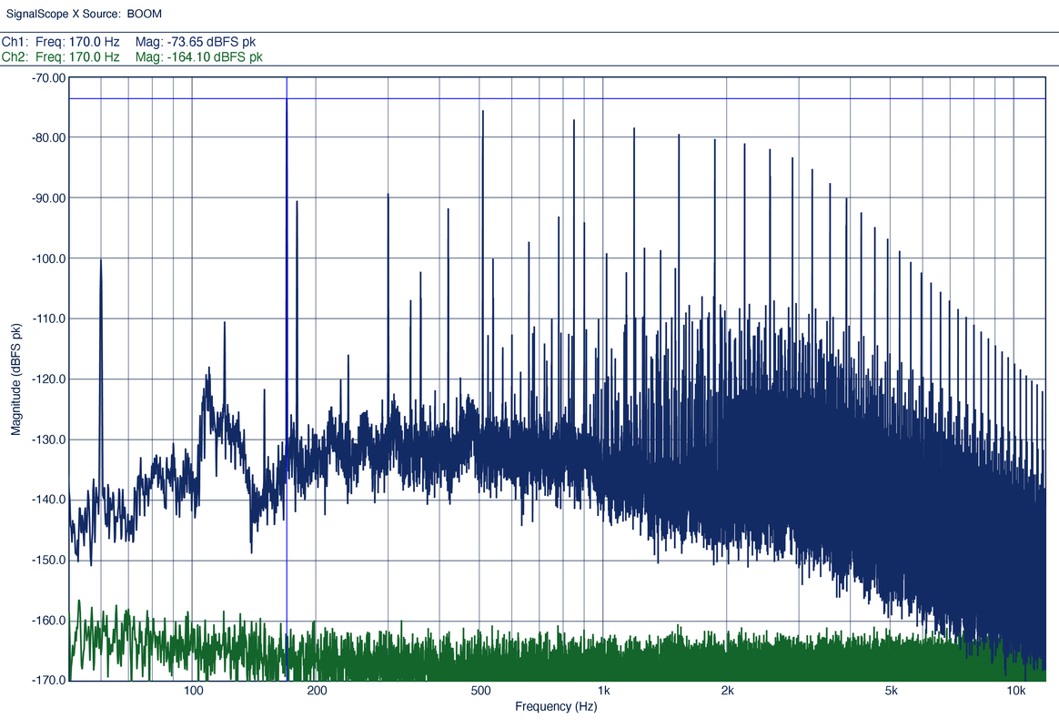
So it does within about .1 db, a bit lucky to get that close. Here is the plot with the cancellation in place: 
At 170 Hz this is not as good as expected. I do not know why, but cancellation requires both amplitude and phase matching. This will require some more work to understand. |
|
|
|
Post by ms on Mar 7, 2024 14:48:35 GMT -5
Yes, so the noise cancellation coil looks like this: 
Underneath the cover (on the right) is a bobbin with 500 turns of # 41 wire. That is wrapped in copper shielding tape that is grounded. More details on the coil later, but for now here is the spectrum with the cancellation in the circuit: 
The line at 170 Hz is 30 db lower; the line at 510 is only about 22 db weaker, but it seems that the hum cancellation is successful. The hum harmonic at 180 is down by less than 10db. Why? The first possibility is that the residual is the result of an electric field, which would not have been canceled by this method. It could also be caused by a hum source that is very close, and so the pickup and canceling coil do not see the same strength field. I suspect that the first is more likely. The line at 60 Hz has increased; maybe there was a change, such as a motor turning on. I do not think it is a result of the cancellation coil; we will see later that this did not happen in the equivalent measurement for the bridge pickup. So we see why we need to make our own hum source to get accurate measurements. |
|
|
|
Post by ms on Mar 7, 2024 11:49:20 GMT -5
What is the guitar configuration? Is this an RWRP pickup pair in the middle position? With no cancellation coils installed? NO, no RWRP. |
|
|
|
Post by ms on Mar 7, 2024 11:11:18 GMT -5
In this discussion we will look at reducing hum in the pickup signal from magnetic fields using one or more coils that can have either air or ferrite cores, depending on circumstances discussed later. First, we need a measurement system. This is necessary to get meaningful numerical results, especially because hum from both electric and magnetic fields is present, and the methods for reducing them are very different. I call the thing in the picture a field bucket. Reminder: magnetic fields are caused by currents [charge in motion], and coils are useful for various purposes. 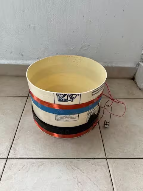 T T
The two spaced coils are called a Helmholtz coil and are usually used in applications requiring a nearly constant field inside. The guitar body with pickups and cancelation coils is too big, and so I turn it on its side and put the guitar body and measurement electronics about ten feet away. The axes of the coils point towards the field bucket. The neck is removed and replaced with a small piece of wood (such as used in finishing a body) and mounted in a heavy drill press vise. This is the guitar used for the tests shown first: 
The P-90 pickups are under-wound to give a sound similar to PAF humbuckers. The field bucket is driven with a 170 Hz square wave at about 15 volts RMS; its resistance is about 200 ohms. A square wave is used to give a distinctive pattern of harmonics. First, look at the time domain response of the output of the neck pickup: 
The pickup sees time rate of changes in the flux density, and so we get output at the transitions of the square wave. The bandwidth of the pickup rounds what would otherwise be sharp spikes. Disconnecting the current at the field bucket makes the distinctive waveform disappear, and so we know we are looking at the magnetic interference from a source we have created. Now for the frequency domain: 
We have pickup from our source, 60 Hz and harmonics, and also other unknown sources. The 170 Hz from the square wave is the biggest signal, and it is marked with a horizontal blue line. The first four harmonics are marked with vertical dashed lines to identify them; the higher harmonics are obvious. A square wave should have only odd harmonics because of its symmetry, but a weak 2nd harmonic is visible, resulting from imperfections somewhere in the system. The harmonics fall rapidly above 3 KHz because of the bandwidth of the pickup. There is almost no 60 Hz, and the harmonics increase, reaching a maximum at 300 Hz, falling rapidly at higher frequencies. For cancellation, we should not worry about anything above about a KHz. The control cavity in the guitar is shielded; however, we expect the 60 Hz and harmonics to be the result of both electric and magnetic fields. The next post looks at the effect of an air core cancellation coil. |
|
|
|
Post by ms on Mar 7, 2024 6:32:37 GMT -5
"The hum bucking configuration will cancel out some of the lower harmonics to a degree, but the upper harmonics will still make it through." This is not useful, except to suggest looking at everything else he writes very carefully. |
|
|
|
Post by ms on Mar 6, 2024 10:30:44 GMT -5
The string is sensed over the pole piece; the location of the sensing changes little with changes in the winding.
|
|
|
|
Post by ms on Mar 6, 2024 6:25:14 GMT -5
What is an electromagnetic noise source? You need to test with electric and magnetic fields separately for useful consistent results. But getting rid of electric fields is easy. A thin metal shield is adequate, so there is really nothing to learn there. Magnetic fields are harder.
|
|
|
|
Post by ms on Mar 5, 2024 6:19:12 GMT -5
An excerpt from the first paragraph from the above-linked page: Most of the Jackson employees that were hired to wind pickups were women.
This is because women have a greater tolerance for this very meticulous process.
Men generally have less patience for a process such as winding pickups.
Struck me to where I had to post this before continuing reading. That was 1985. Still a lot better than what would have been written in 1965. |
|
|
|
Post by ms on Mar 4, 2024 14:34:29 GMT -5
Section 9 on shielding (and also on hum bucking, although this is not in the title) contains many errors. They follow from the misconception that both shielding and humbucking reduce hum from "electromagnetic fields". Shielding reduces hum from electric fields, while humbucking reduces hum from magnetic fields. A propagating electromagnetic wave (radio, tv, cell phones, etc.) has both kinds that oscillate together. This is not usually a problem for guitars because the frequency is so high and guitars do not efficiently "detect" the modulation on the wave.
Section 11 on single coil versus humbucking says that the major difference in sound is a result of harmonic canceling from sampling one versus two regions on the string. This is a real effect but minor, and only affects the lower frequency strings. The relevant harmonics are high number and out of the bandwidth of the system on the higher frequency strings. Humbuckers sound darker because they have higher inductance. Well, not all single coils have lower inductance; for example, a P-90 has high inductance. The myth is that a P-90 has good high frequencies because it is a single coil pickup, but it does not.
Also, stacked hum buckers do not have cancelled bass. There is some loss in output level from coupling between the coils at all frequencies.
|
|


