|
|
Post by vonFrenchie on Jun 5, 2006 17:41:01 GMT -5
I just read through the QTB page again (just for kicks) and I realized exactly how dangerous guitars are. Thats why I want to shield my Rhoads. Its better safe than sorry. Here are some pictures of the control cavity. 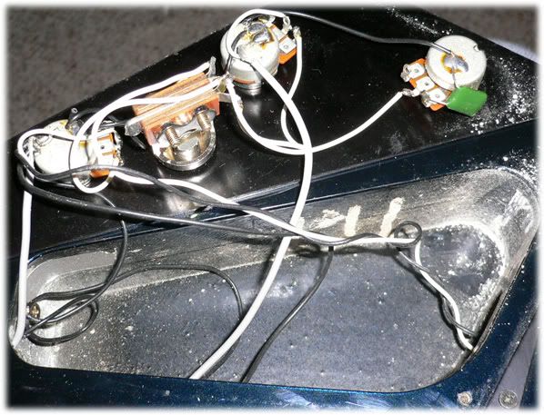 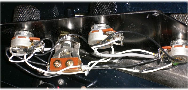 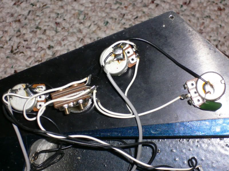 |
|
|
|
Post by RandomHero on Jun 5, 2006 18:08:46 GMT -5
That's gonna be EASY. You're a lucky one. That cavity shape will be especially condusive to using copper tape, which is the best kind of sheilding, and not driving yourself mad doing it. =D
|
|
|
|
Post by vonFrenchie on Jun 5, 2006 18:32:57 GMT -5
Thanks for the motivation. I have a schematic that I drew up (I cant get my camera in so you can see EVERYTHING) 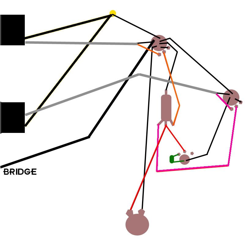 That yellow dot on the top is a screw that is driven into the body of the guitar. |
|
|
|
Post by UnklMickey on Jun 5, 2006 18:40:59 GMT -5
hey vonFrenchie,
2 Questions:
are you going to keep the volumes forward wired like you have in the drawing, or make them independent?
do you plan on keeping the signal ground and the shielding ground separate, until they are joined at a single point?
unk
|
|
|
|
Post by vonFrenchie on Jun 5, 2006 18:47:42 GMT -5
for the first one, I didn't know that they werent indepentent (i play with them all the way up... all the time) so I guess Id prefer to keep them this way because I really like the sound of my guitar.
for the second I really dont know. I just read the guide (kinda) and decided that this would be a wise thing to do.
|
|
|
|
Post by vonFrenchie on Jun 5, 2006 21:18:23 GMT -5
I actually plan on having a Les Paul style setup. Like this one (two independents)  |
|
|
|
Post by UnklMickey on Jun 5, 2006 22:14:49 GMT -5
hi vonFrenchie, if you always keep your volumes maxed, it won't really matter if you do your volumes forward, or reversed. from your pix, it looks like it's already wired like this:  |
|
|
|
Post by vonFrenchie on Jun 6, 2006 16:24:57 GMT -5
Yeah thats how its wired (pretty much). The picture I posted is what I want it to be. I'd prefer to have two different tones. I'm going to buy another pot (I already have a cap). From the 2 and 2 what should I do to shield it?
|
|
|
|
Post by UnklMickey on Jun 6, 2006 16:53:03 GMT -5
if it were up to me, i'd connect all of the signal grounds to a common point. for instance the the where the black wire connects to the left lug of the bridge volume (top center of the first pic).
all the black wires from the pickups, the wire from left side of the other volume control, the tone caps, etc would all connect there.
if you aren't going to use the "shock protection cap", you can use the back of that pot. and connect the back of that pot directly to the left lug of the volume control
but if you are going to use it, the cap would connect from the signal ground to the back of the pot.
none of the other cases of pots and switches will be wired to the ground circuit. they will be grounded through the copper foil on the back of the pickguard.
in either case the string ground and the shields from the pickups will connect to the back of the volume pot.
and the cavity foil will come up and over the edge of the cavity far enough that it almost reaches the edge of the pickguard when it is installed.
the cavity will only be grounded when the pickguard is in place.
sound like a plan?
|
|
|
|
Post by vonFrenchie on Jun 6, 2006 17:34:54 GMT -5
Yeah... if only I actually understood it. All I got out of it was if im not going to use the 400v capacitor I can use the back of a pot, and that all the grounds should be connected to a common point (the pickups/bridge are already connected to a screw in the side of cavity). I plan on using that capacitor unless it would be too complicated.
|
|
|
|
Post by UnklMickey on Jun 6, 2006 17:41:31 GMT -5
Yeah... if only I actually understood it..... sorry, i tend to do that. picture...thousand words....yadda,yadda,yadda.... i'll draw you up something tomorrow that will include the cap. and make the words unnecessary. unk |
|
|
|
Post by vonFrenchie on Jun 6, 2006 18:38:20 GMT -5
The capacitor I have (left over from redoing my bass) is a .022mfd and the one on the tone pot that is already in my guitar is .047mfd (or ufd, which ever you prefer). Which capacitor gives more treble than the other.
Also how do I know what I have for pots, as in 250k or 500k?
|
|
|
|
Post by UnklMickey on Jun 7, 2006 13:22:49 GMT -5
The capacitor I have (left over from redoing my bass) is a .022mfd and the one on the tone pot that is already in my guitar is .047mfd (or ufd, which ever you prefer). Which capacitor gives more treble than the other.
Also how do I know what I have for pots, as in 250k or 500k? hi vonFrenchie, the cap doesn't "give" treble, it "takes it away". the 0.047uF will cut to frequencies closer to midrange. the 0.02uF will cut only to frequencies that are a bit higher than that. when your tone control is on 10 neither one does hardly anything at all. since your guitar came with HBs, it's almost certain you have 500k pots. if you have a meter, you could measure them. here's your drawing, freshly diced:  shielding circuit is drawn in green. signal grounds are black. i couldn't tell for certain from the pix, if the pickup cables have a wire for the signal ground that is separate from the shield. if they have only hot and shield, do NOT connect the outer conductor to the shield circuit. connect it to the signal ground (black). and don't allow the frame of the pickup to touch anything in the shielding circuit. don't connect wires from the pickups to the shielding circuit. those green connections going from the pickups are valid ONLY if you have 2 wire + braid. unk |
|
|
|
Post by vonFrenchie on Jun 7, 2006 14:13:56 GMT -5
if they have only hot and shield, do NOT connect the outer conductor to the shield circuit. Im not quiet sure what that means. The wire coming from the pickups has a grey rubber cover then the wires from the ground then a white rubber casing then the wires that are active. |
|
|
|
Post by UnklMickey on Jun 7, 2006 14:28:11 GMT -5
...then the wires that are active. is there one active wire on each cable, or two? |
|
|
|
Post by vonFrenchie on Jun 7, 2006 14:48:40 GMT -5
coming from the pickup? I dont know I cant really tell even if I have the pickup out of the guitar.
Also what cap would you recommend for the neck/bridge and for the shock protection.
*EDIT*
I just read on Guitar Electronics about the single/four wire thing and I have single wire pickups. 1 active and 1 ground.
|
|
|
|
Post by UnklMickey on Jun 7, 2006 15:19:49 GMT -5
John Atchley is recommending a 0.33uf, 400V metal film capacitor, for the shock protection.
i suppose a 0.2 would be just fine.
higher voltage is O.K., but lower isn't recommended.
for the tone caps, that's a "season to taste" sort of thing.
i'd use the 0.022.
i'm certain Wolf would choose the 0.047.
neither one of us is wrong.
so it sounds like your HBs are hot and ground only.
the ground will go to the black connection at the volume pot.
completely disregard the green wires indicated in the drawing, that go from the HBs to the shield ground.
unk
|
|
|
|
Post by vonFrenchie on Jun 7, 2006 15:24:36 GMT -5
I want to have a nice dark sound. Right now (w/ a .047) the bridge pickup is perfect but the neck pickup reaches some higher tones. Would you say the .022 goes on the neck and .047 would go on the bridge. I kindof assumed that a .33ufd 400+ volt capacitor would be fine but I just wanted to make sure (I cant find a 400v capacitor at .33 ufd.) 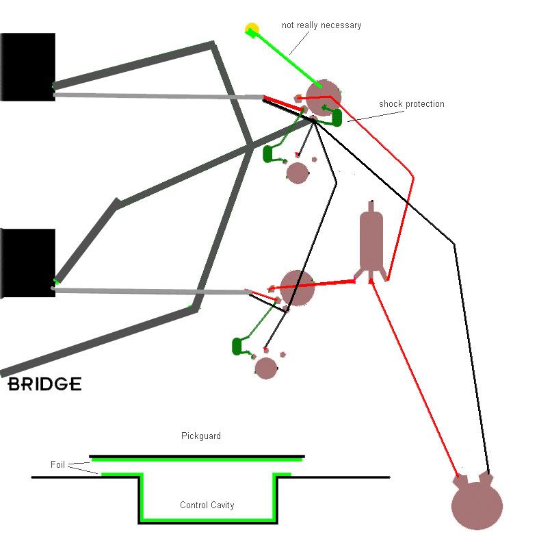 Does that look like the proper schematic? Does the switch need any grounding (like it has now). |
|
|
|
Post by UnklMickey on Jun 7, 2006 15:55:41 GMT -5
a 0.022 on the neck tone will allow more of the lower part of the treble to still be present (as compared with the 0.047), when the tone is set to "0".
if you want it to be darker, then you'll want a 0.1
the drawing is definitely wrong the string ground shouldn't go to the signal ground.
i think you and i are "getting our wires crossed" (pun inteneded).
are there actually separate wires right now, coming from cases of the pickups that i had as green and you now have as dark gray?
or do you mean that to indicate the connection to the cavities under the pickups?
unk
EDIT:
the frame of the switch will get it's ground from the foil of shield circuit, just like the cases of the pots do.
|
|
|
|
Post by vonFrenchie on Jun 7, 2006 16:32:31 GMT -5
They are still the pickup mounting plates/bridge. Then am I supposed to solder the pot to the point at which the pickup plates/bridge connect or just leave it to touch the pickguard.. Also... nice one
|
|
|
|
Post by UnklMickey on Jun 7, 2006 17:02:09 GMT -5
if the outer conductor of the pickup cables connect (internally) to the pickup mounting plates, don't add the wires. they will bypass the shock protection cap.
if the outer conductor of the pickup cables only connect to one end of the coil of the pickup, then use the wires, and connect them to the shield ground (yellow circle).
if there is any doubt, DON'T add the wires.
the string ground should go to the yellow circle.
all the pots will touch the foil on the backside of the pickguard.
the foil on the pickguard will make contact with the foil of the control cavity, if you run the foil over the edge of the cavity the way it is in the drawing.
therefore, it won't be necessary to use a wire from the back of the volume pot to the yellow circle. it won't hurt anything if you use it too.
unk
|
|
|
|
Post by vonFrenchie on Jun 7, 2006 17:05:38 GMT -5
Does cap voltage matter for the tone pots?
|
|
|
|
Post by UnklMickey on Jun 7, 2006 17:30:53 GMT -5
yeah, they have to be at least 1 volt! lol
seriously, the signal is so small, any voltage rating you can find will be much higher than needed, so voltage rating is not an issue here.
unk
|
|
|
|
Post by vonFrenchie on Jun 7, 2006 17:34:08 GMT -5
alright... now the problem is finding a .33uf capacitor. Is it possible to put multiple capacitors in series and have the voltages add up. Like 4 .33uf 100v capacitors lined up to equal 400v?
|
|
|
|
Post by UnklMickey on Jun 7, 2006 17:46:34 GMT -5
yes, and no.
the voltages will add up, but the capacitance will divide.
if you put 4, 0.1 uF caps in series that would give you 0.025 uF.
[EDIT:]if you put 4, 1 uF caps in series that would give you 0.25 uF. [/EDIT]
that should work just fine.
unk
|
|
|
|
Post by vonFrenchie on Jun 7, 2006 21:08:08 GMT -5
|
|
|
|
Post by UnklMickey on Jun 8, 2006 15:10:16 GMT -5
...The way you said it makes it sound funny... and confusing. .... guilty! (and not just in this instance) but i really wasn't trying to confuse. if i was i would have said that in series, the reciprocals of the capacitances add. 1 / C series = (1 / C 1) + (1 / C 2) + (1 / C 3)... or i could have even said that the resultant capacitance would be the product of the capacitance over the sum. C series = C 1 * C 2 * C 3 ... / ( C 1 + C 2+ C 3 ...) but if i had said: "for identical capacitors in series divide the capacitance by the number of capacitors", that probably would have made the most sense. those caps you linked to should work fine. you must have deciphered what i meant. your conclusions are right. BTW i edited my previous post. i shifted everything by a decimal point in my first example. the resultant 0.025 uF would have been marginal. metal film would be better in general. but for this application, it won't make a bit of difference. unk |
|
|
|
Post by vonFrenchie on Jun 8, 2006 20:48:15 GMT -5
You got it the second time around. The first time I looked at youre first post I was pretty confused but then I realized it was Capacitance over # of caps. Everyone makes math mistakes (I think I could make the mistakes for five people).
Also about the schematic. The two pickup mounting plates and the bridge are grounded directly to the copper tape. All the pots and pickups go through the shock cap (3 in my case) and then the cap goes to the case of a pot. No other wires needed because the pot is touching the copper tape. Correct?
|
|
|
|
Post by UnklMickey on Jun 8, 2006 21:00:17 GMT -5
yes, that's correct.
if the tape tears easily, you will need to make sure the pots don't turn while you are tightening them down. you might destroy the connection if the tape gets mangled.
some large flat (metal) washers between the pots and the tape will minimize the possibility of tearing the tape.
unk
|
|
|
|
Post by vonFrenchie on Jun 8, 2006 21:50:35 GMT -5
Yeah there are already two washers between the pots and the guard already.
|
|


