|
|
Post by aquin43 on Aug 21, 2022 6:20:27 GMT -5
I found the way that the eddy current losses are modeled and the frequency response determined in the Gitec Pickup Wizard interesting so I tried it out in LTspice with a made up pickup rather like an Armstrong Johnny Smith model which has a strong dip in the response. The losses are modeled as resistances across splits in the overall inductance and the exciting voltage is converted into the current that would pass through the lossless total inductance. Some of this current passes through the loss resistances instead of the inductances, producing the correct frequency response. The inductance values are entered as parameters so L3 can be made equal to L1 + L2. The input voltage source is loaded with L3 and the dependent current source B1 is set equal to the current from the input voltage source which is equal to the current through L3. The load as switched on and off by stepping the value of R6 between 1m and 1G. 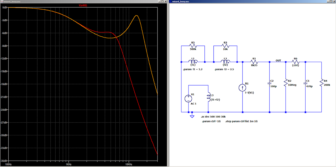 |
|
|
|
Post by antigua on Aug 21, 2022 15:08:43 GMT -5
|
|
|
|
Post by aquin43 on Sept 10, 2022 12:15:29 GMT -5
The idea seems to be that each section of the coil in the model receives an induced voltage in proportion to its inductance as a fraction of the overall inductance. Then, due to the circulating current in the resistors representing the eddy current losses, each coil loses some of that voltage as the frequency rises. The circuit arrangement is just a way of putting the voltages in place. Another way would be by putting the voltages in directly: 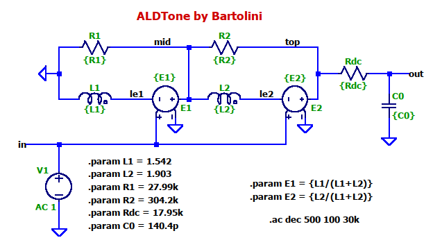 |
|


