|
|
Post by cynical1 on Jan 5, 2023 14:22:52 GMT -5
EDIT: This thread wanders a bit and has multiple revisions to drawings. If you want to bypass all of this, the final drawing is located here
So, I'm working on the wiring layout for the Peavey again... Space is tight in the cavity, so it turns out the PTB mod I was planning won't fit. DireStrat's post Don’t know where to add this capacitor to TBX circuit got me thinking on how replacing two pots with one pot sounded like a solution. The video in the thread was helpful. Quick background, this is a 1988 Peavey Foundation I've had since about 1992. It's a poplar body, maple neck bass with two Peavey Super Ferrite pickups. I did shield it and put a Schaller 3D-4 bridge on it, but otherwise it's stock. It always had a pretty sing to it...but it never had any cojones. Hence, the introduction of a P-Bass pickup crammed right above the old neck pickup and the just below the neck...somewhere between where the 23rd to 25th fret would go...if it existed... I'll have to slant it and squeeze it a tad, but that's already worked out So, I came up with this: 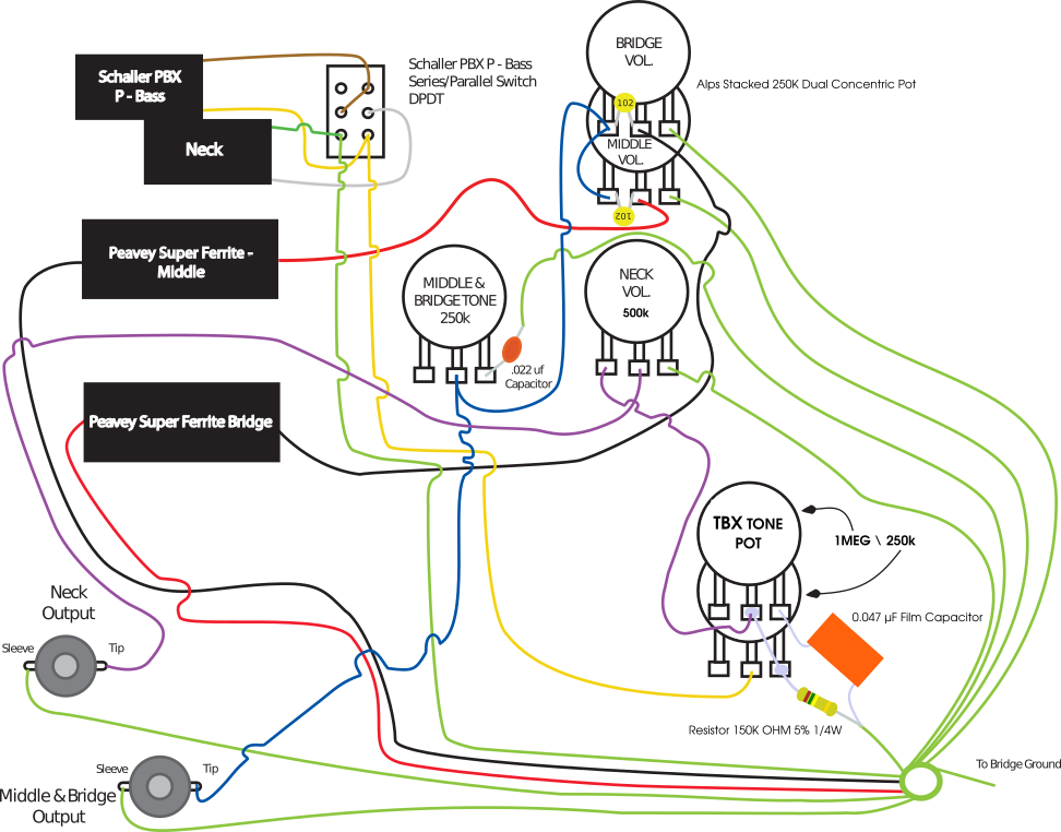 And yes, the middle and bridge pickups are out of phase. Peavey did this to make them humcancelling...as they're single coils. Here's the wiring from the horse's mouth: 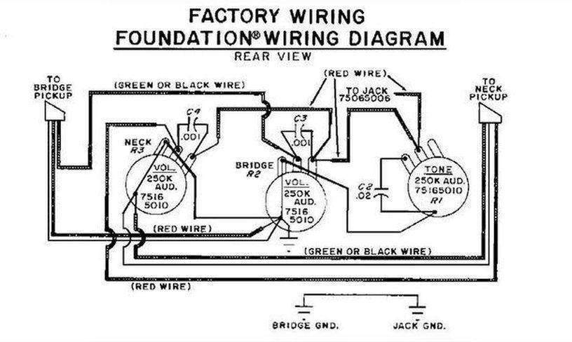 I just replicated everything from the original as close as possible from this. I don't really want to screw with the original wiring and pickup placement. I like it where it is. There are two outputs for a reason...the same one Billy Sheehan gives. Run one output to a clean channel and the other output to whatever evil the mind can conjure. You can distort the Hell out of the middle and bridge...losing all your low end...then put it all back with the neck output. I'm certain trial and error will find the sweet spot. Anyone who has been here a while has seen previous versions for this bass. It's come apart and gone back together a few times over the years, but this time I think is the keeper. Nothing is soldered...and not everything is ordered...so if anyone sees anything glaringly stupid, feel free to shout it out. HTC1 NOTE: Title edited for posterity, 20230110.
|
|
|
|
Post by newey on Jan 5, 2023 19:06:46 GMT -5
Well, the neck series/parallel switch looks fine, and the rest seems to follow the original Peavey diagram, so I think you're good to go.
Since you're tearing it apart anyway, have you considered using a switched jack for one of the two output jacks? I have that planned (and wired already, although the rest of the project languishes) for my stereo Tele project.
That way, you don't always have to plug into a separate amp (or into a "y" junction, or similar) to use all 3 pickups. This would be wired such that, if a cable is plugged into just one jack (presumably tyhe Mid/Bridge, then all three pickups are operable, but plugging 2 cables in then switches the neck output to that other jack. That seems the most logical way to do the stereo wiring. Since you only have pots and no pickup switching, it's even easier in this setting than in my Tele, where I have to separate the switching as well.
|
|
|
|
Post by cynical1 on Jan 6, 2023 6:07:04 GMT -5
I started out with a pickup selector switch...and a few other assorted switches... I put it back together when I discovered the control cavity was not a Tardis... The more I thought about it, the more I began to realize that the thing I loved about this bass was the simplicity of it.
I looked at going down the path Yamaha took with their Billy Sheehan Signature, but it seemed to make more sense to just grab an A/B/Y box for when I'm not going to two amps. That, and I've lived 30 years with it having just the two pickups and one output, so I figured it would be best to keep it simple.
HTC1
|
|
|
|
Post by sumgai on Jan 6, 2023 12:17:44 GMT -5
The Thing About Stereo Outputs.... If we go back to newey's original thread dealing with split outputs, one pup per jack, we'll find a short discussion that's even more apropos here. Namely, when using two amps, we open up the possibility, nay, the almost-certainty, of having standing waves within the environment. To not make everyone find and revisit that earlier thread, what that means is that two sources (speakers) of the same tone will fill the room (that's my 'environment', and it doesn't matter what size of room) from different points. As the wavefront of a note is pushed out from Speaker A, it will encounter that same wavefront from Speaker B. Somewhere in the room, that encounter will take place. Now, as we've long known with the strings on our axe, one of two things will occur when this encounter takes place: either we'll have a reinforcement (aka a resonance), or we'll have a null point, i.e. a cancellation. That's essentially a 'dead zone', and not one where we hear pleasant harmonics. All of this is based on a large number of factors, but it starts with the two sources (speakers). Where they are placed is probably the biggie, and the direction they're pointing is likely #2 on the Hit Parade. Since the room is also "not a Tardis", there will be walls, and the reflections therefrom will also have an effect; good, bad, or otherwise. This is exactly why we see multiple amps/cabs on stage in one location, not all over the place. Errr, that is, until we get to stadium-sized venues, then that multiplicity becomes the Order Of The Day, for obvious reasons. Now I'm not one to put a damper on the idea of stereo outputs, but, and especially in the bass range of frequencies, there is a tendency to try to overcome the dead spots with more volume. And guess what? It doesn't work. In fact, higher volume just makes the problem worse. So all I'm saying here is, it's neat to experiment with tone and tonality FTM (for the Mojo!), but when it comes time to hit the stage, it is never a bad idea to keep the K.I.S.S. principle in plain sight.  HTH sumgai |
|
|
|
Post by cynical1 on Jan 6, 2023 17:18:27 GMT -5
I found a standing wave with just one amp...but as the bartender said, it ain't the Civic Opera...it's a bar, kid... In all likelihood, my playing out days are over. I just don't feel like hauling all the crap from the house to the venue and back again.
This will probably be the neck output going straight in and the neck bridge and middle will go into an amp and get mic'd. Saves playing the same part twice.
And no stereo. Just binaural mono...
HTC1
NOTE: Corrected typo. I was borrowing someone else's fingers when I typed this...
|
|
|
|
Post by sumgai on Jan 6, 2023 22:30:36 GMT -5
And no stereo. Just binaural mono. .... he said, without having looked at a good thesaurus lately. Good joke there, champ.  But seriously, the fact is that while you may not ever play out again, other viewers here are looking at our ideas, and they have their thinking caps on just like you and I have 'em on. That's all I wanted to say, that there are oft-forgotten little factoids that will jump out and play Mr. Murphy when one is considering multiple outputs from their axe. HTH sumgai |
|
|
|
Post by JohnH on Jan 7, 2023 17:15:24 GMT -5
Hi cynical1, there's a couple of things about the design intent that I'm not quite getting.
In the 1st post, you describe thinking about PTB, and then moving to a TBX to reduce knob count. TBX's can be adapted per Phostenix, to make a bass or treble cut on a single stick. But the way the TBX is shown in the diagram doesn't seem to look like that.
Also, if a bass cut is to be part of the the design as on a PTB , then that part usually needs to go before a volume pot, I see the diagram has independent vols, pre-volume, which I know is common and works well on basses, but may reduce effectiveness if there's a bass-cut intended.
Can you describe the overall wish-list for knobs and what you'd like them to do?
|
|
|
|
Post by cynical1 on Jan 9, 2023 10:59:18 GMT -5
Hi cynical1, there's a couple of things about the design intent that I'm not quite getting. And that was exactly why I posted it...I do better with sawdust... And this is where losing one knob was the "look, squirrel" motivation to add it. I Googled more diagrams, pictures and variations for the TBX configuration on bass and guitar that I admit to knowing damned little about it now. First off, everything on the Peavey side of this diagram is really just a removal of 35 year old electronics for something from this century...although a part of me wants to recycle the old "102" capacitors... That, and the more I looked at adding another pickup to this bass, I didn't want to screw up what already worked well on it. That's why the two Peavey pickups kept their own circuit and output intact. Now, the Schaller P-Bass pickup... I know that from where this pickup is likely to reside that it's going to be a bucket for mud. I don't necessarily want to lose that...but I want to be able to pull it back from merely attracting whales to complimenting the middle and bridge pickup. One of the first things you notice when adding any distortion or fuzz to a bass is that all the bottom end just evaporates. The point of the separate outputs was to allow me to process the signal from the middle and bridge pickup into one amp, then run the neck clean into another amp and be able to recreate in one take something that always took two...provided I could remember what I played the first time... So yes, to your question, I am looking for the TBX configuration to act as a cut, either treble or bass, depending on what I want to do with the output from that pickup, or the amp I plug it into. As witnessed, I'm not actually certain what needs to change, or what variables a given change introduces. I just swagged it from the video and a couple of articles. To paraphrase Edison, I haven't failed...just found another way that didn't work... HTC1 |
|
|
|
Post by cynical1 on Jan 9, 2023 13:08:07 GMT -5
But seriously, the fact is that while you may not ever play out again, other viewers here are looking at our ideas, and they have their thinking caps on just like you and I have 'em on. That's all I wanted to say, that there are oft-forgotten little factoids that will jump out and play Mr. Murphy when one is considering multiple outputs from their axe. I couldn't agree more. This is just another in a long line of building something somewhat unique in purpose and function. Fender builds Strats, Gibson builds Les Pauls...imitation may be the sincerest form of flattery, but not terribly original or interesting... I have little choice in the matter...however, I have never endorsed anyone willingly following my ideas in practice... HTC1 |
|
|
|
Post by JohnH on Jan 9, 2023 17:46:02 GMT -5
Thanks I get it now! really two separate circuits, with the bass and treble cut just on the neck. So I reckon, overall its fine - just need to rearrange the TBX to do Phostenix' bass and treble cut and pick some cap values to try. guitarnuts2.proboards.com/thread/8890Two other thoughts - I see the star grounding scheme, and no doubt you can consider if that will work out easier to wire up than just ground each pot back and taking ground connections to the nearest pot. i dont think there's a fundamental difference in a guitar. But also related to grounding, two outputs are feeding two different amps or stompbox chains, but with a common ground hence linking the input grounds of these. Will there be any ground loop issues? If so, the neck circuit could be made to be entirely disconnected to the B and M circuit, with its own ground. |
|
|
|
Post by cynical1 on Jan 9, 2023 18:58:09 GMT -5
Point well taken. I never gave a thought to splitting the grounds. Glad you mentioned that. I'll change that now. For me, using a copper washer to solder everything to in a star ground is just easier for me...I'm never going to screw it up by overheating it... Thanks for taking a look at different cap and resistor values. My brain still hurts from when chrisK tried to explain it to me... I really only want the ability to cut the bass and treble. The cap values shown in the drawing are based on the values tested in the video that direstrat posted. I live in EmpiricalLand...  HTC1 |
|
|
|
Post by JohnH on Jan 9, 2023 19:23:11 GMT -5
On values. I reckon that the treble caps are working really in the same way as they are in any basic treble-cut circuit, so your favorite cap values for treble cut on a bass should still apply!
For bass cut, if its based on testing then that's best. My guess would have been 2.2nF and try double that as an option.
|
|
|
|
Post by cynical1 on Jan 9, 2023 19:31:58 GMT -5
Cap values aside, am I looking at something like this with one resistor and 3 capacitors to achieve a treble cut one way and a bass cut the other way :  Or do I just lose the .0?? uF capacitor from the drawing...or am I still lost in the forest? I've never put a treble bleed on a bass...to keep it uniform I can match the value on the Peavey side. Sorry for being so thick on this. HTC1 |
|
|
|
Post by JohnH on Jan 9, 2023 20:39:13 GMT -5
Hi cyn1, I hadn't seen that diagram version with the  mystery cap. Where's it from? The one I linked to above, from what we mirrored off the original Phostenix site, just has tbe two caps. So I'd suggest that as a basis. EDIT, apologies, I remember it's a recent tweak to give treble cut as well as bass cut one way. But still, I'd start with the basic 2-cap version. |
|
|
|
Post by cynical1 on Jan 10, 2023 2:03:52 GMT -5
Hi cyn1, I hadn't seen that diagram version with the  mystery cap. Where's it from? It's from the thread that started me down this path, from direstrat. So, we're talking this one, right?  Just so I'm following along, in the video, from the same direstrat post, linked somewhere above, the guy in the video swaps out the 1Mohm resistor for a 150k or 180k resistor, and swaps the .022uF for a .047uF capacitor. This is what my original drawing details. The .001uF capacitor is the same one on the Peavey volume pots, so it seems to follow the same value would work on the neck. Thanks for pointing me in the right direction. Let me know if I'm still missing something. HTC1 |
|
|
|
Post by cynical1 on Jan 10, 2023 12:19:28 GMT -5
I don't expect this to be ready for Prime Time yet, but is this getting closer? 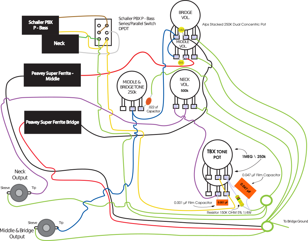 I added the 0.001uF capacitor to the 250k side of the TBX and moved the 0.047uF and 150k resistor to the outside lug of the 1M pot. I also added a separate star ground for the neck output. I believe this is configured per guitarnuts2.proboards.com/thread/8890 thread. The only thing I'm sure I have wrong is the cap and resistor values running in parallel from the 1MEG side of the TBX pot. Initially, the values were swagged based on the capacitor being soldered to the 1MEG side and the resistor being soldered to the 250k side. I am well past my pay grade on this one. I'll kept Googling to see if anyone else has done this on a bass and see what they used...and I found the Duff McKagen\Jazz Bass Special version of the TBX: 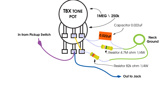 This isn't even close to what we were discussing, but what does this do in relation to what we were discussing? Again, more dispatches from EmpiricalLand... HTC1 |
|
|
|
Post by Yogi B on Jan 11, 2023 7:58:55 GMT -5
I added the 0.001uF capacitor to the 250k side of the TBX and moved the 0.047uF and 150k resistor to the outside lug of the 1M pot. ... I believe this is configured per guitarnuts2.proboards.com/thread/8890 thread. Your wiring matches but you have the 1Meg/250k labelling swapped in both the above text & in the diagrams. When assembled, the 1Meg gang is the closer to the control knob. The original purpose of Fender's larger 4.7Meg resistor is pop reduction, allowing the cap to discharge when the 250k gang goes no-load (5—10 on the knob). Smaller values will technically be better (lower R*C time constant), but I doubt it'll make much difference in reality — C is already relatively small, as is the voltage supplied by the pickups. Tone-wise: the resistor, even when reduced to 150k, has little impact. At lower tone settings, a slight reduction in Q of the filter and a slight volume loss will occur. As compared to no parallel resistor at all (infinite parallel resistance), simulations say: with the tone all the way down there'll be an overall loss in volume of about 0.5dB, with a further reduction of 0.8dB at the resonant peak. You'd have to go quite a bit south of 150k before the choice of a specific resistor value starts to have noticeable consequences, and at that point the resistance will be so small as to mask the fact that it's even in parallel with a capacitor (the resistor would have significantly lower impedance than the cap throughout audible frequencies). I don't see what's special about that — though that's likely the bass, not the TBX — even so: those are no different from Fender's usual values. |
|
|
|
Post by cynical1 on Jan 11, 2023 12:48:22 GMT -5
Your wiring matches but you have the 1Meg/250k labelling swapped in both the above text & in the diagrams. When assembled, the 1Meg gang is the closer to the control knob. Yes I did. Sorry, seasonal dyslexia... It'll be fixed on the next iteration. I can appreciate that...especially since I'm pushing the amp harder than a guitar would... Is there a sufficient level of "pop" reduction at 1Mohm, as in the original design? I'm guessing no resistor in parallel is a bad idea with the capacitor coming off the 250k pot...is that a safe assumption? I admit to having no formal training in electronics. I also admit to having a very shallow pool of usable knowledge acquired from 15 years on this forum. I'm trying to grasp what each of these designs do...and why. Putting the two side by side, let me try an elaborate on my two primary points of confusion when looking at these two options:  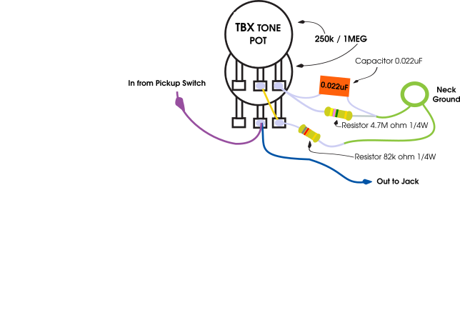 1.) Signal Path: In the original version on the left, the signal arrives from the pickup switch at the TBX on the 1MEG pot on the outer right lug and departs from the 1MEG center lug to connect to the outer left lug of the volume pot. In the Duff McKagen version, the signal comes from the pickup switch, then arrives and departs at the center lug of the 1MEG pot straight out to the jack. 2.) Resistor vs. Capacitor: On the left is a .001uF capacitor across the outer right and center lugs of the 1MEG pot and on the right is an 82k resistor from the outer 1MEG lug to ground What are the advantages, disadvantages or unique characteristics of these differences? Inquiring wood butcher would like to know... Aside from the TBX and the price, probably nothing special. I've never played a Jazz Bass Special or Duff McKagen version...all the jazz basses I ever saw or touched had your typical volume/tone pots and maybe a blender pot. I'm not terribly concerned about a volume loss. I really only want to cut bass or treble from the neck pickup. All the definition in the tone is coming from the middle and bridge pickups. The neck pickup is just there to reinforce the bottom end. Ask sumgai...I like my pedal board...and these Super Ferrite pickups love overdrive and distortion. I really like the idea of processing the same note out to two different signal chains for independent processing...all the trash with none of the bottom end loss. 45+ years ago I would have never considered this...as very few in their right mind want to haul two bass amps and cabinets to a gig...especially when the drummer's merdo filled up most of the van... Now that I'm approaching "judgmental" age, the idea of trying something different appeals to me. I only record now so this is just another toy to play with in my pursuit to keep myself entertained and off the streets... HTC1 |
|
|
|
Post by Yogi B on Jan 12, 2023 23:50:52 GMT -5
I can appreciate that...especially since I'm pushing the amp harder than a guitar would... Is there a sufficient level of "pop" reduction at 1Mohm, as in the original design? Empiricaland probably has better answers. What numbers can tell us that it'll take 238ms for the a 22n cap to discharge to a tenth of it's initial voltage via a 4.7Meg resistor, 4.7 times longer than it'd take through a 1Meg resistor to reach the same threshold. Or alternatively, if given the same 238ms time period, the cap paired with the 1Meg resistor will be reduced by a factor of ten 4.7 times to 1 / 50119 of the initial charge (i.e. 74dB less than with the 4.7Meg over the same time period). Well that'll definitely have the most pop, relying on the caps own leakage (ideally zero) to discharge any remnant voltage. But again this isn't likely to pop as much as, for instance, a pedal could. Out of curiosity I looked up what value of discharge cap Gibson use(d) on the varitone cap switch: 10Meg. Though the size of that value is somewhat dictated by the need to have 5 of them in parallel (after a 100k resistor is placed in series with the signal) without causing too much loading. The point being that the largest cap in the varitone is 220n and yet I've still never read complaints about switch popping. First it's probably a good idea to include a plot of the resistance tapers of each gang of the pot look like: The 250k gang (red) is somewhat similar to a log taper, just squished into half the rotation and going no-load at the centre detent (as depicted by the vertical line shooting off to infinity). The 1Meg gang (yellow) is like one of the gangs of an M/N blend pot (I forget which of M/N is which): staying at comparatively zero resistance for the first half then rising approximately linearly over the second half. The Duff McKagan (original Fender) version uses the 1Meg gang as a variable resistive load placed in series with the 82k resistor. At the centre detent the 250k pot is already no-load, and the 1Meg pot has very little resistance so the loading is set by the value of the resistor (82k being equivalent to a regular 250k tone pot set to about 7, or 500k set to about 6). Turning the pot upwards, to ten, adds resistance in series with the 82k resistor up to 1082k thereby reducing the loading on the pickup and 'adding' some treble zing. The modded wiring uses the 1Meg gang to bypass a low-cut cap, again starting at the centre detent the resistance is low — effectively shorting the cap, removing it from the circuit. As the resistance of the pot increases: the combined parallel impedance of the cap & 1Meg pot remains low for higher frequencies (thanks to the cap), but increases for lower frequencies. This additional series impedance forms a voltage divider with the resistance of the volume pot (and anything else further down the signal chain) to form a high pass filter. Visually, over the full range of the pot, the results look something like this: Fender's Default TBX is in red, the modded HPF/LPF version in green, and for fun a regular 1Meg tone pot is plotted in blue (mainly for comparison against the default TBX). The jump between 49% and 50% is caused by the sudden transition of the 250k gang going open. |
|
|
|
Post by cynical1 on Jan 13, 2023 17:43:00 GMT -5
Visually, over the full range of the pot, the results look something like this: Fender's Default TBX is in red, the modded HPF/LPF version in green, and for fun a regular 1Meg tone pot is plotted in blue (mainly for comparison against the default TBX). The jump between 49% and 50% is caused by the sudden transition of the 250k gang going open. This is brilliant. Just show the bass player a cartoon and he gets it... Actually, it took me hours to translate this into Empericalese... So, just to confirm my translation...and insure I'm following along at home, the resistor in parallel with the capacitor coming off the right outer lug of the 250k pot is only there for "pop" protection. The .001uF capacitor on the 1MEG pot between the outer right lug and the center lug is there to allow the bass cut. Thanks. HTC1 |
|
|
|
Post by cynical1 on Jan 19, 2023 15:51:55 GMT -5
The weather sucks today...so I drew up what I hope is the final version of wiring up the Peavey. Here's what I came up with: 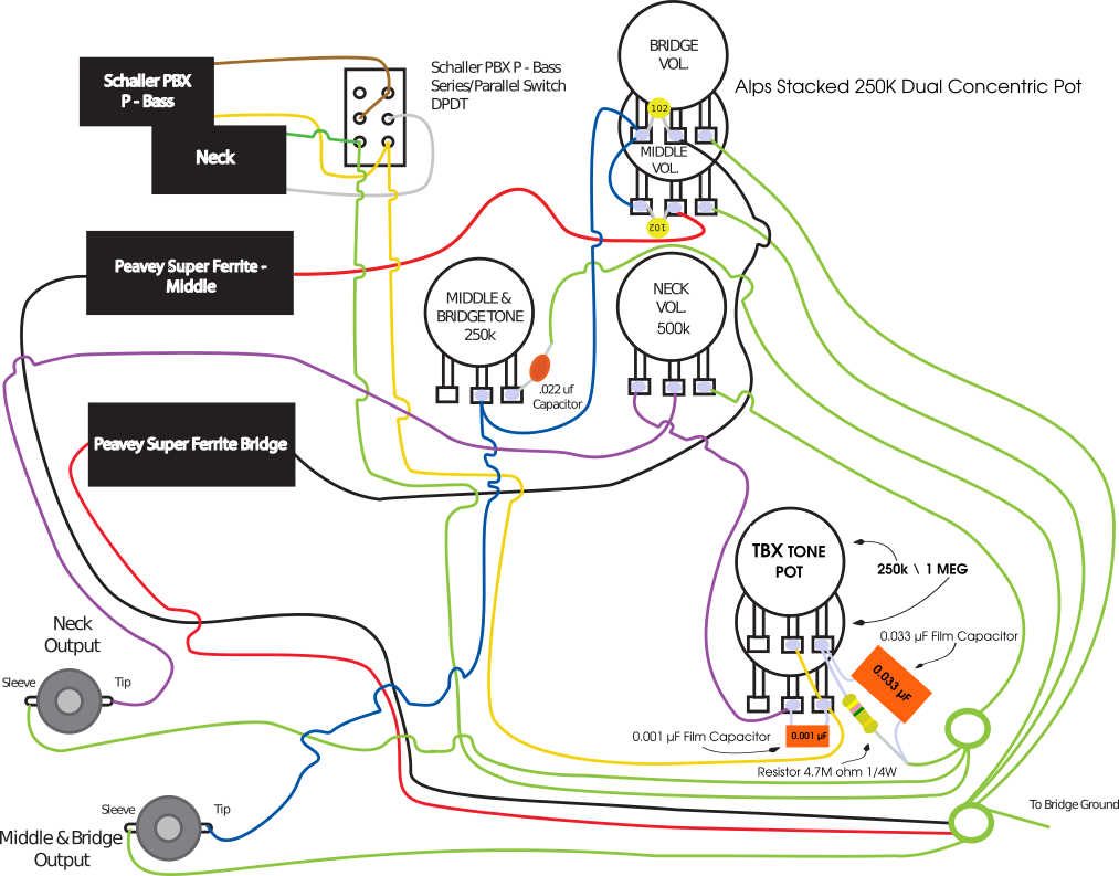 JUSTIFICATIONS & ASSUMPTIONS from EmpericalLand: JUSTIFICATIONS & ASSUMPTIONS from EmpericalLand:1.) I left the Peavey wiring in the same stock configuration. (now middle and bridge) Physical components may change, but signal path and competent values are the same. 2.) I chose a 500k volume pot for the neck to preserve as much high frequency as possible. 3.) The TBX is wired per the "Modified TBX Tone Control for Treble & Bass Cut" detailed within this thread, with two exceptions, both on the outer right lug of the 250k pot: - The .022uF capacitor detailed is replaced by a .033uF capacitor
- The 1Mohm resistor detailed is replaced by a 4.7Mohm resistor
The logic, or lack of, used in these changes went like this:
- Since I only have from 0 to 5 on the 250K pot, I didn't want to have the highs drop too soon or too late in the rotation. I just threw a dart between .022uF and .047uF.
- If the 1Mohm resistor is there for "pop" protection...and if 1Mohm is good...4.7Mohm must be better. If it works for Deaf McKagan it should work for me...
If anyone out there sees anything out of a blue cloud in any of this, please feel free to shout it out. I haven't ordered the last of the parts, so now is the time to stop me. Happy Trails Cynical One |
|
|
|
Post by Yogi B on Jan 24, 2023 22:48:34 GMT -5
2.) I chose a 500k volume pot for the neck to preserve as much high frequency as possible. This choice also has an effect upon the bass cut — for the same value of bass-cut cap / pot: a higher value volume pot will have a lower cutoff frequency & offer a reduced depth of cut. Typically (at least insofar as what G&L used e.g. in their L-1000 basses*) a 250k volume pot is paired with a 2.2nF bass cut cap. Now you might be thinking: "compared to the values proposed here, that's half the resistance & (roughly) double the capacitance, so it evens out". That's true of the first of the above points (cutoff frequency), but the second (depth of cut) is dependent upon how large the bass cut pot is in relation to the volume pot. A 1Meg bass-cut pot paired with a 500k volume & an assumed 1Meg following input impedance works out as a maximum of a 4× bass reduction (i.e. −12dB, as seen in the prior plot), with a 250k pot the maximum bass reduction is increased to 6× (−15.6dB) — though note this assumes the pickup's DCR is negligible, in reality a lower value pot will also slightly reduce the output at minimum cut too (but typically we're only talking a few tenths of a decibel). I don't know if any of this really matters to you, but it is a discrepancy from the 'norm' and if it is deemed worth 'fixing', what's to be done, other than switching to a 250k volume pot? Note that on your TBX pot there's an unused third lug on the 1Meg gang, this can be used to blend in (as the bass is reduced) a 500k (or so) resistor in parallel with the volume pot. Though, as there is no such thing as a free lunch, this will still contribute an additional 1.5Meg load upon the pickup even at the neutral position, giving total loading of 375k, but that is still better than 250k. (Also, just to be clear, you'd be using the larger 2.2nF cap value with this configuration.) (For a while I have been thinking about a bass cut for my own bass. I'm inclined towards a deeper cut over a narrower band of frequencies so the above is the type of arrangement I've been looking at. And, although in my case the plan is to use a stacked concentric pot for treble/bass rather than a TBX thus offering a little more flexibility, I've yet to settle on a set of component values.)
* Also note the 1nF cap, C3, that is in parallel with the pickup no matter what — an idiosyncrasy of (most?) G&L basses. This along with your wish to preserve the design of Peavey's original wiring is why I haven't admonished the use of treble bleeds with independent volume wiring (think about what happens when you turn one volume to zero). |
|
|
|
Post by cynical1 on Jan 25, 2023 10:27:39 GMT -5
This choice also has an effect upon the bass cut — for the same value of bass-cut cap / pot: a higher value volume pot will have a lower cutoff frequency & offer a reduced depth of cut. That's exactly why I asked. Here in EmpiricalLand we tend to miss these finer points. I'll make the correction to 250k on the volume pot for the neck pickup and post a final for posterity. Yeah, as much as it may be recommended, I really want to leave the Peavey side of the equation as it came from the factory. The Super Ferrite pickups have something unique about them, and after 30 years with this thing I can find the sweet spots in my sleep. The nature of the beast with this bass is that you can't zero anything out. You get noise by dropping the volume to 0 on either pickup. And they can be noisy...but whichever pickup you choose as primary, with the volume on the other pickup set to 3 it's quiet. The tone control has hardly ever left 6 or 7 since I bought it. Again, sweet spot to my ears. If I had more room in the control cavity I'd just leave the existing wiring intact and add the neck pickup circuit around it...or a blend pot...but there's about as much free space as a New York City apartment... Thanks for sticking with me on this little project. Pictures, animations and explaining it like I was 5 really does help. I love this bass...don't ask me why... It'll be a bit before I have pictures as the neck needs some love, too... Shoemaker's kids... HTC1 PS: The five year old is back again... Regarding the TBX: In the drawing you linked above, provided I'm reading it right they have a .047uF and a 6.8k resistor coming off the 250k pot of the TBX pot. I have .033uF capacitor and a 4.7Mohm resistor. The 1MEG pot has a .0022uF capacitor, where I used the spec from the archived drawing at .001uF. I'm guessing the used the .0022uF capacitor on the 1MEG pot because of the lower range of the instrument. Correct me if I'm wrong. I understand the .047 capacitor coming off the 250k pot. I'm a little lost on the 6.8k resistor. I'm not Edison, obviously, but that seem a lot smaller than the 1Mohm or 4.7Mohm resistor values we've been discussing. It may be nothing important, but I don't understand the wide variance. |
|
|
|
Post by Yogi B on Jan 25, 2023 23:27:38 GMT -5
I'm guessing the used the .0022uF capacitor on the 1MEG pot because of the lower range of the instrument. Correct me if I'm wrong. In practice, as far as I know, G&L use(d) the same cap value across both bass & guitar. Why Phostenix chose the smaller 1nF I don't think is detailed anywhere. I could speculate that 1nF was used because it's a commonly used value for treble bleeds — or contradictorily speculate that since the G&L circuit is the best known example of a passive bass cut a 2.2nF cap was likely tested first, but 1nF was Phostenix's preferred value after experimentation. The 6.8k resistor is in series with the cap (as opposed to the others which are in parallel). This gives basically the same effect as if you could only turn the tone control down to about 1 or 2, rather than all the way down to zero. It's the same principle as Fender's Greasebucket Tone Control, only without the frankly unnecessary extra 100nF cap. |
|
|
|
Post by cynical1 on Jan 27, 2023 20:32:18 GMT -5
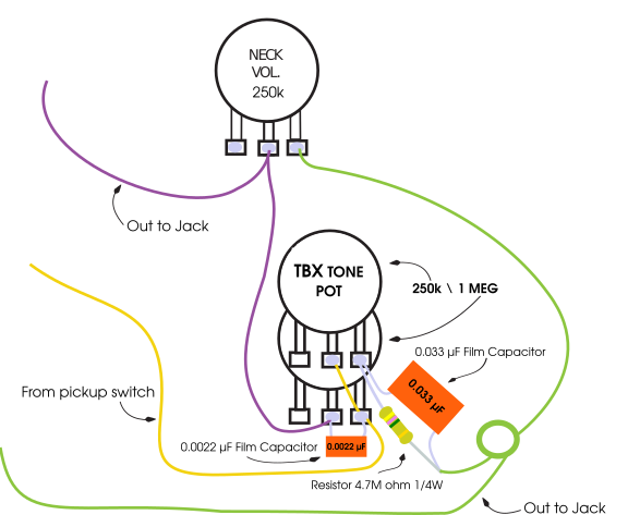
I really am trying to understand the forces at play here. Let's wrap this up so I can ice my brain . Yea or ney... without taking this back down a road where my eyes will just glaze over again...if I built what's detailed below, will I have: - A bass cut on the TBX...
- ...as well has a bump to the high end, as detailed in Yogi B's previous animation...
- ...and will I not have to worry about a pop when passing the notch on the pot?
 Thanks again for sticking with me through all of this. I hope this is it as much as you guys do... HTC1 |
|
|
|
Post by kitwn on Jan 30, 2023 6:21:33 GMT -5
Yogi B, I love the animated frequency response plot! What software do I need to make one of those?
Cynical1, I really can't work out what's happening from the how-it-looks-inside-the-guitar drawing, way too confusing for my simple mind. I always work with schematic diagrams for designing/assessing circuits and only draw the real-world layout while the soldering iron is warming up.
Kit
|
|
|
|
Post by cynical1 on Jan 30, 2023 21:06:21 GMT -5
I really can't work out what's happening from the how-it-looks-inside-the-guitar drawing, way too confusing for my simple mind. I always work with schematic diagrams for designing/assessing circuits and only draw the real-world layout while the soldering iron is warming up. There's nothing too nefarious going on. It's essentially upgrading components from the original bass, the Peavey side, then the new neck pickup is on it's own output circuit. The TBX circuit is there the roll back some of the low end which is inevitably going to show up locating the neck pickup so close to the neck. The purpose is the same as Billy Sheehan's. One channel going to amp A with all of your effects, and the other channel goes to amp B, which is mostly clean. This way you get the all dirt and get to keep the low end. The bass has a moderate sized control cavity, but with the second output, extra switch and pots it went fast. The TBX is the last part I'm struggling with. There are some mechanical things I need to do on the bass as well. 30 years tends to leave its mark. I never formally learned how to read schematics and struggle with them still. The wiring diagrams are just another flash from EmpiricalLand. HTC1 |
|
|
|
Post by Yogi B on Feb 1, 2023 2:51:14 GMT -5
if I built what's detailed below, will I have: Yup.Ish, (assuming you're talking about the resonant peak at ~3kHz) it'll be lower with a 250k vs 500k volume pot... I did mention loading but didn't explicitly describe the effect upon the resonant peak, I should've really posted an accompanying diagram... so I guess I'll do that now: The green trace is the same as in the previous plot (500k volume, 22nF treble-cut cap, 1nF bass-cut cap). The purple plot is what you have in the latest diagram (250k volume, 33nF treble-cut cap, 2.2nF bass-cut cap). The yellow trace is what I suggested as compromise, with an extra 510k resistor from the lower left (as drawn) lug of the TBX to ground (500k volume, 33nF treble-cut cap, 2.2nF bass-cut cap). (All three would look more or less identical at 0% if not for the treble-cut cap change.) Also, as I didn't mention it previously, the P-Bass pickup model is the Fender's Pure Vintage '58 from GuitarFreak (almost certainly based upon antigua's measurements). Hopefully not.
I love the animated frequency response plot! What software do I need to make one of those? It's not so much a piece of software as it is a combination of applying the relevant calculations to a mathematical model of a pickup (usually taken from JohnH's GuitarFreak) and a rough understanding of SVG animations — gluing those two together via a programming language (plus appropriate libraries). A little more specifically: my go-to language is Python, so I'm using Numpy for the maths & Plotly for the graphing. Plotly has the functionality to export (static) SVGs which I use as a basis for the image, then patch that file to include the animation cycling over the results obtained from varying the pertinent parameter. |
|
|
|
Post by cynical1 on Feb 1, 2023 7:17:52 GMT -5
Sweet. Questions #1 and #3 are resolved in 5 syllables. Now, for #2...just so the inner 5 year old understands: I can't dissect YogiB's animation, but I can scrape the .svg file, open it in Inkscape to export it into a .png image...so I can post it back. 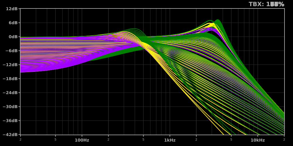 Anyway, what I see is an overlay of all plotted curves. I looked at this and watched the animation for quite some time this morning...thank God the wife wasn't awake...she'd have my meds changed... After the initial WTF moments...I went back to EmpiricalLand to center myself. Going under the following premises - The instrument in question can produce fundamental notes from around 41hz to 330hz
- It can produce harmonics to ~4kHz...or in a neighborhood close to it...
- The 250k side of the TBX is too close between the 3 options to make it a significant consideration in the final decision.
- On the 1MEG side, GREEN curve cuts the least bass
- On the 1MEG side, PURPLE and YELLOW both cut more bass and have similar curves
I started thinking this way: - The GREEN curve is not what I'm looking for.
- On the bass cut side of the TBX (50%-100%), they all peak above 2500hz, with PURPLE being the most subdued in the crowd.
- 2500hz is typically finger squeak territory...hmmm...
So, I like the PURPLE option. See, show the bass player a cartoon and he gets it...sort of... You see, along with the inner 5 year old, I also seem to have an inner masochist...so I have to ask... What happens when I put the "extra resistor from the lower left (as drawn) lug of the TBX to ground", as detailed in the YELLOW curve\option, when it's in the circuit with a 250k volume pot...all other things being equal... HTC1 |
|
|
|
Post by Yogi B on Feb 2, 2023 0:01:12 GMT -5
Sweet. Questions #1 and #3 are resolved in 5 syllables. Even though I did accidentally make #3 a double negative: hopefully you will not not have to worry about popping. Between 100% & 50%, this: Here, the red trace is the same as the previous purple trace (i.e. no additional resistor), the others proceed decreasing in resistance from 1.2Meg stepping every third E24 value down to 91k. Namely those are 1.2Meg, 910k, 680k, 510k, 390k, 300k, 220k, 160k, 120k & 91k. |
|