|
|
Post by crazymanandy on Jun 20, 2007 15:18:38 GMT -5
Hey guys,
What cap value do you generally prefer for the Tele tone pot?
I'm also wondering what you think would be best with a 3 pickup Tele:
Tele Bridge (Alnico III) 9.1K | P90 (Alnico II/V) ~7.9K | Tele Neck (Alnico V) 7.6K
CMA
|
|
|
|
Post by ChrisK on Jun 21, 2007 11:58:10 GMT -5
|
|
|
|
Post by crazymanandy on Jun 21, 2007 14:15:38 GMT -5
Heh, yeh I like that on-on-on idea. I was actually contemplating using a varitone of some sort, but I don't really want to put it on if I can't fit it on the control plate, I've already got a on-on-on switch for wiring the pickups to go on there. I suppose I could use a dual concentric pot for volume/tone to open a little extra room. Or I could just experiment with different caps! Only two screws, right?  CMA |
|
|
|
Post by ChrisK on Jun 21, 2007 18:43:48 GMT -5
Yeah, but them on-on-on (DPDT center-ON) switches are dinky, you can fit two (er, more). The control panel; 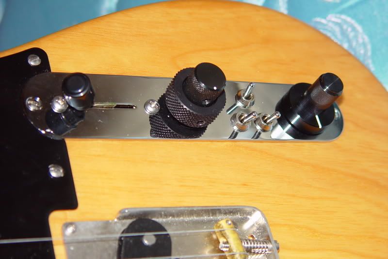 I've done some TeleCrazy things: 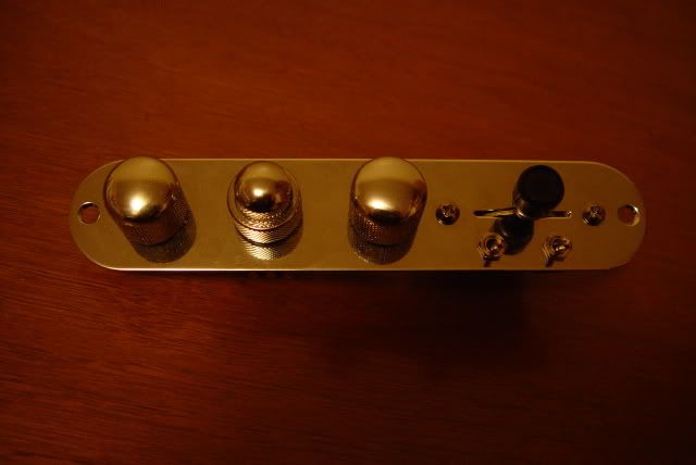 |
|
|
|
Post by crazymanandy on Jun 22, 2007 2:45:44 GMT -5
Your on-on-on cap switch is growin' on me!  Could you draw up a diagram showing that switch and the tone pot? Unfortunately, I can't make heads or tails of the diagram in that thread, lol. Do you find three knobs close together like that to be cumbersome? CMA |
|
|
|
Post by ChrisK on Jun 22, 2007 12:06:07 GMT -5
Yes, but I won't. 'Nuff free fish, You're going to have to learn here. Why not?  Start with the part that sez "OUT" and "COM" and work yer way inward. (You don't have to understand the whole world atlas to read a map of yer hometown.)  The Green wire is Ground, the Orange wire is the pickup(s) signal Output. P1 is the volume pot (with a treble bypass cap). The applicable (and only) tone pot is P3. The applicable tone cap selector switch and capacitors is S2. Switch S3 is unrelated to the volume and tone controls and selects three effective cap values (none, 330 pF, and 1,300 pF) to detune the bandpass response of the pickups (makes 'em warmer and "peaky", kinda like Texas or sumpthin'). The rest of the stuff is just switching and wiring that does exactly what the "Modes" chart sez (peel slowly and "see"). These are the heads, you can forget the tails. THERE WILL BE A TEST ON THIS. |
|
|
|
Post by crazymanandy on Jun 22, 2007 15:39:47 GMT -5
Yes, but I won't. 'Nuff free fish, You're going to have to learn here. You're no fun! Everyone else gets a sucker, where's mine! Mostly because I haven't learned to read electrical diagrams, but that's my fault. Your explanation of the diagram really helps clear it up a bit. Now, on the DPDT switch, you've got the blue lines representing wire. What are the little arrows? Thanks Chris, CMA |
|
|
|
Post by ChrisK on Jun 22, 2007 18:01:57 GMT -5
|
|
|
|
Post by crazymanandy on Jun 23, 2007 16:29:52 GMT -5
|
|
|
|
Post by ChrisK on Jun 24, 2007 19:33:47 GMT -5
OK, give it a try. Be sure to mind where I have each value of cap.
|
|