|
|
Post by frozensheep on Jul 14, 2007 16:50:34 GMT -5
i'm planning on giving strat some mods. Sheilding. 2 volume mod. and 2 series parallel switch after a bit of lurking around i found this a digram for 2 volumes and a 1 tone. a phase switch and a parallel/series switch.  the one thing i noticed is the pick-up selector seems to be changed. I think it was made for diffrent positions without a switch. I have a neck-pick-up on switch on mine so i didin't need that, and now i'm not 100% if this diagram will work on my strat I dunno if this is a bit demanding buy can someone change the diagram so it shows 2 parallel/series switches. One for the neck and one for the neck and the bridge. and my other question is, are all those caps neccicary? will my guitar sound crappy without it? and are those yellow boxes soldering lungs or are they caps?. |
|
|
|
Post by JohnH on Jul 14, 2007 17:16:00 GMT -5
frozensheep - welcome to GN2, and thankyou for your interest in the two-volume Strat, which is this design: guitarnuts2.proboards45.com/index.cgi?board=schem&action=display&thread=1165712655The 5-way switch is intended to represent that found on a standard Fender Strat, as viewed from the back, with its two sets of lugs, one on each side. There are other switches that look different but do the same job, such as a type used on some Squires where the lugs are in a single line of 8, with the poles being the two centre lugs. The way it is wired in this design is different to normal however - as necessary to make this particular design work. What is the issue that you are raising? The yellow rectangles are the caps - thats how they look for the ones I buy so thats how I draw them, but they are not special types. There are two used for treble bleed (1nF), maintaining treble tone at lower volume, and two tone caps for each side of the double tone pot (22nF). They all have a job to do in this design. The whole switching design works as a unit, and while it may be possible to tweak it here and there, there is a risk of messing up what already works. So I shall decline to hack into it in this case, but anyone else who may wish to redraw it is very welcome to try. regards John |
|
|
|
Post by frozensheep on Jul 14, 2007 21:09:31 GMT -5
^ kay, i understnd now.
I'm gonna skip the trebel bleed for the reason that it makes lowering the volume more noticable and it gives a diffrent sound.
I don't want to buy a stacked tone pot.
Is there a way to wire it with just one master tone pot.
and if i wire the output of the first parallel switch to the second switch
to make it a parallel switch rather than a phase switch, would that work.
or should i stick with the original design.
|
|
|
|
Post by JohnH on Jul 14, 2007 22:17:23 GMT -5
^ kay, i understnd now. I'm gonna skip the trebel bleed for the reason that it makes lowering the volume more noticable and it gives a diffrent sound. Try it without if you want - but they are intended to keep the sound more consistemt at lower volume The tone pot is a dual-ganged 500k, with a single knob. It is a standard part and is not expensive. The reason for the double pot is because of the two volume controls, allowing the tone pot(s) to be on the pickup side of them, where they will operate consistently at all volume settings. You can have a single pot, wired from ground to hot output (dark blue lug on the 5-way, in the diagram), but it will suck when used at low volume. It's not that simple. But it would be possible to use the switch to put M and N in series with each other, so N, M or N+M all get replaced by NxM. If you pull both series switches, you would have BxNxM is all positions of the 5-way. It would need a full re-do of the wiring diagram, which unfortunately I am not able to do at this time. Thats a good idea John |
|
|
|
Post by frozensheep on Jul 15, 2007 0:38:45 GMT -5
Thanks for the help john.
ummm one last question, is it possible to do all of that without the dual-ganged pot.
because i'm not 100% i can get my hands on one of those.
and two do all the pots need to be a 500k, i'm planning on using 250k's because of the sound.
|
|
|
|
Post by JohnH on Jul 15, 2007 1:21:44 GMT -5
250k should work OK for the volume pots, if you prefer the slightly warmer less edgy sound. If you have to use a single tone pot, it will work, but it will be better at full volume than at reduced volume. It will be oK at either full vlume, with reduced tone, or at reduced volume, if tone is at max. With both reduced, the tone control will cut much deeper than usual into the treble. If you dont use tone much, it may be OK. Id recommend a 500k tone though, even if the volumes are 250k.
John
|
|
|
|
Post by frozensheep on Jul 15, 2007 12:12:02 GMT -5
^ cool, i only really use the tone knob for cutting my trebel eq's to make my stat sound like a bass.
and i only use the volume for volume swells so i'm o.
thanks for the help man.
|
|
|
|
Post by frozensheep on Jul 17, 2007 0:28:38 GMT -5
i wired it exatcly in the picture, exept i didin't use the double tone pot.
now the bridge position is on,
on every position.
what do i do?
i'm have a killswitch and a neck-pick-up on switch installed.
Since the bridge is always on, i don't think i need the neck-pick up on switch anymore so i wired it to be a bridge off switch.
i hate my strat now.
|
|
|
|
Post by JohnH on Jul 17, 2007 3:45:20 GMT -5
thats bad luck, Im sorry to hear that. But you have extra/different switches which are not in the design, so it is therefore not according to the diagram. The design has been built and we know that it works, so there will be an error in your wiring somewhere, which may be due to the extra switches or due to something else. How about you draw what you have built, then we can take a look, and/or post some photos of the wiring?
John
|
|
|
|
Post by michaelcbell on Jul 17, 2007 7:56:10 GMT -5
Just so this isn't a binary conversation, I'll chime in - pics and/or drawings make it much easier to diagnose a problem than simple descriptions. For example, you could take a picture of a tone pot instead of saying:
The middle lug connects to the right-hand lug of the volume pot, the left lug connects to the sleeve of the jack, and the right lug isn't connected to anything.
Now picture a whole design described that way... ew!
a coupla pics and we'll be on our way.
|
|
|
|
Post by frozensheep on Jul 17, 2007 11:47:03 GMT -5
 thats how i wired the killswitch and the neck pick-up on switch. ps: i only did the two volume mod since i couldn't get my hands on a push pull. plus i haven't shielded my guitar so i have to do the ground lung thing. since that didin't work i just wired the neck pick-up on switch as a bridge off switch so i'm able to have all the pick-up combos. the problem is that makes switching from neck to bridge is harder. |
|
|
|
Post by sumgai on Jul 17, 2007 13:08:46 GMT -5
frozen,
Two things......... One, is that diagram immediately above the way you did it, or the way you want it come out looking like?
Two, does your switch match that image exactly? There are now many variations of the Strat-style switch, and there's no rule that they have to be wired up the same way, internally. If your switch is different internally, then you'd experience the "one pickup on at all times" problem you described.
Take everything back off the selector switch, and use a multimeter to test each and every pair of terminals, in all five (5) positions. As you find the connections, write down them down. Next, draw a new diagram from that list (or table) of combos you found. Now check to see if this work matchs perfectly with the switch in your original diagram. If not, then it'll be time to do some converting - making a new diagram with the new switching arrangement.
Let us know what you find out.
HTH
sumgai
|
|
|
|
Post by frozensheep on Jul 17, 2007 13:50:26 GMT -5
frozen, Two things......... One, is that diagram immediately above the way you did it, or the way you want it come out looking like? Two, does your switch match that image exactly? There are now many variations of the Strat-style switch, and there's no rule that they have to be wired up the same way, internally. If your switch is different internally, then you'd experience the "one pickup on at all times" problem you described. Take everything back off the selector switch, and use a multimeter to test each and every pair of terminals, in all five (5) positions. As you find the connections, write down them down. Next, draw a new diagram from that list (or table) of combos you found. Now check to see if this work matchs perfectly with the switch in your original diagram. If not, then it'll be time to do some converting - making a new diagram with the new switching arrangement. Let us know what you find out. HTH sumgai i just use an i pod to check the pick-ups that are on. i thinking of just wiring it back up to the original format because the two volume mod dosen't seem to be able to controll two pick-ups at once. when you go neck and bridge , only the neck volume is on. etc. thanks for the help. |
|
|
|
Post by michaelcbell on Jul 17, 2007 13:56:19 GMT -5
how does one test pups with an i-pod?
If you're interested in actually doing the mod, don't give up. take sumgai's suggestion and we'll be able to give you a lot more feedback.
|
|
|
|
Post by michaelcbell on Jul 17, 2007 13:58:05 GMT -5
plus, pics or YOUR actual wiring diagram (not an ideal, but what you actually did) would go a long way in helping us help you...
|
|
zamzara
Apprentice Shielder

Posts: 49
Likes: 0
|
Post by zamzara on Jul 17, 2007 13:59:19 GMT -5
If the 5 way looks like this: www.guitarpartsonline.com/images/electronics/Switch.jpgthen the two common lugs are probably internally connected. If it's the same as the one I have, this can be fixed by opening up the switch and scraping off the very short PCB track in between them with a sharp knife. |
|
|
|
Post by sumgai on Jul 17, 2007 17:33:02 GMT -5
zam,
Good point, and good research. +1 for you! ;D
sumgai
|
|
hugh
Meter Reader 1st Class

Posts: 50
Likes: 0
|
Post by hugh on Jul 17, 2007 18:33:47 GMT -5
Hell, I'd just wire exactly as JohnH describes, and then modify from there.
Sometimes its best to work in steps. When you have so many variables, its hard to figure out where the problem begins.
|
|
|
|
Post by michaelcbell on Jul 17, 2007 18:42:48 GMT -5
that also works... do be sure to test everything in the exact configuration you think is JohnH's before you move on...
|
|
|
|
Post by JohnH on Jul 17, 2007 21:44:31 GMT -5
Thanks for chipping in guys. The diagram posted above by frozen sheep is not equivalent to my one, and shows linked poles on the 5-way and a 1V 2T configuration. We need to understand what has been built, but I agree that Zamzara may have put his finger on an important issue, if we are talking about those lugs in-line switches.
John
|
|
azrael
Rookie Solder Flinger

Posts: 17
Likes: 0
|
Post by azrael on Oct 25, 2007 22:14:15 GMT -5
Hey, look, a diagram I drew! |
|
|
|
Post by ChrisK on Oct 27, 2007 0:01:29 GMT -5
FYI Import (boxed) 3/5-way Lever Switch correlated to 3/5-way Fender-style lever switch. 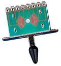 Note that it was easy to discern the switch logic of this unit before someone posted the link to the datasheet that I modified because one "can see thru the PCB".  |
|


