bendmire88
Rookie Solder Flinger

Posts: 14
Likes: 0
|
Post by bendmire88 on Nov 19, 2007 14:38:56 GMT -5
 Did'nt know where to post this, so i figured here would be good. You can just delete this thread after you get the pic if you want to. ;D Just got my camera back today so here you go.  And here's another one..... 
|
|
|
|
Post by ChrisK on Nov 20, 2007 0:22:11 GMT -5
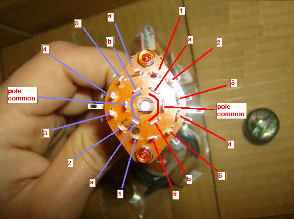 Here's the top view with annotations. 1 thru 6, probable switch positions/selected contacts. Pole common a, b pole common bus. This wafer will be designed to enable the manufacturer to make a 3P4T, 6P2T, and 1P12T wafer as well as the 2P6T as on this switch. This can be known from the fact that there are 6 inner terminals (all but two are cutoff in this 2P6T wafer). The manufacturer could have left three on for a 3P4T, 6 on for 6P2T, or just one for 1P12T. There's a little more to it than just leaving the terminals on, they actually have to build the wafer with different inner ring contacts and a different mechanical stop for each. As you can see from this, these inner terminals are used for the pole common bus. That being said, in our case there will be one of three possibilities a. The existing pole common will be electrically common with its one neighbor on both of it's sides. This would be the pole common and the missing terminals marked (a) and (b). b. The existing pole common will be electrically common with two of its neighbors on its one side, c. The existing pole common will be electrically common with two of its neighbors on its other side. Most likely, it will be case a. I drew a semicircle to indicate this for each side/half of the top wafer. Each half of the wafer will be identical in switching. The wafer below will most likely be identical to the top wafer. Now, to verify this, look at the second annotated picture. One can see that there is a top contact wafer and a round switch contact wafer just below it. This is the same case for the bottom contact wafer and its round switch wafer below it. The top contact wafer has a short contact run for each positional terminal and a pole contact run the angular length of all contacts in its group. In this case, it will be six switch contacts in angular length. The round contact wafer just effects a moving bridging contact (in this case there is one per pole, or two on this 2P6T wafer). If you look at the switch from the side, you will see these items and, as you rotate the switch shaft, you'll see these contact move from position to position. 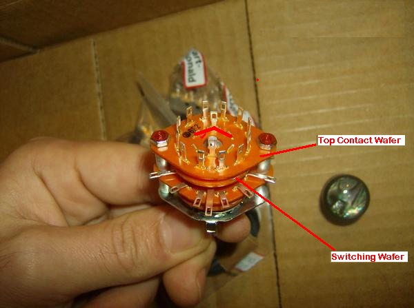  This is the long explanation that goes into a bit of detail. I would just use my digital multimeter to measure the contact closures for each switch position. I presume that you will use your digital multimeter to measure the contact closures for each switch position to verify things. If you don't have one, go buy one.  If you would like to use my annotated version of your picture as a reference, once you measure the actual contact connections we can create a "data sheet" for it and post it in our "Reference" section. Just rotate the shaft all the way one way, measure the same pole common contact to find which numbered contact is active, rotate the switch one position, and repeat until exhausted (er, done). |
|
bendmire88
Rookie Solder Flinger
Posts: 14
Likes: 0
|
Post by bendmire88 on Nov 20, 2007 19:57:49 GMT -5
Ok, got a multimeter today(was planning on borrowing my neighbors but figured i'd just buy one) and i measured the pole and bus. This is my conclusion.. a. The existing pole common will be electrically common with its one neighbor on both of it's sides. This would be the pole common and the missing terminals marked (a) and (b). Then i rotated the moving contact all the way to the little circle thing next to the 6F2 stamp and touched one point to the pole common and the other to a terminal, in that position contact terminal 1 was active, i rotated to every position and each terminal was active in comparision to the position i moved to. Now if this is not what you wanted me to do please tell me, because i've only used a multimeter once before.  By the way, why don't you like slender 80's shredder neck's!?  |
|
|
|
Post by ChrisK on Nov 20, 2007 23:43:56 GMT -5
Most excellent! I am impressed. You now know/verified the switching logic of the switch. Are you indeed telling me that my first annotated picture was exactly correct as to functionality (remember, I've actually never had one of these in my hands)? But I did cheat by having worked an an electrical engineer for way too long (I still have my Intel 4004 and/or 4040 development stuff from '72 methinks). For those that care, that was the first 4 bit microprocessor invented to make custom BCD calculator's easier to customize for Busicom, a Japanese calculator maker. But, there isn't any other way that it could work. After all, it's just an electro-mechanical device (and you can see what it does). You should feel empowered, because you are. While you may still want some assistance in wiring, you are well on your way to creating your own designs since you now "see" more. Once one gets fundamentals into their mind's eye, the rest is just "seeing" and "plumbing". guitarnuts2.proboards45.com/index.cgi?board=schem&action=display&thread=1158705194Everything is just physics anyway. Because I don't have slender 80's shredder hands! I lifted weights continuously when young, go aboot 300#, once wrestled at 255#, and do not float in water. Svelte is a term never applied. |
|
bendmire88
Rookie Solder Flinger
Posts: 14
Likes: 0
|
Post by bendmire88 on Nov 21, 2007 2:31:00 GMT -5
Yes i believe your first annotated picture is exactly right, and might i say.... WOW! Your old. Just kidding ya, with life comes experience(but that goes without saying, so i don't know why i felt compelled to say it. ;D) All righty then, what's the next step? Just wire it up? |
|
|
|
Post by sumgai on Nov 21, 2007 4:32:41 GMT -5
Chris, Methinks I smell a Template Update coming, just around the bend. bendmire, Hi, and welcome to the NutzHouse. ;D Since Chris has formally given you his squeal of approval (he was impressed, not an easy thing to do), it's only fair to warn you that will now be subjected to his sordid attempts at humor. Don't worry, you'll get used to it.  But ferGawdsake, whatever you do, don't get him started reminiscing about dynamite!   Yes, the answer is........ wire it up! Take your time, and check each stage of the job with your new meter. First, connect one pickup to the common terminal for the switch pole of your choice, then hook up the wires from the wiper of the volume control to the three appropriate switch terminals (one long lead and two short jumpers). Test by putting the meter leads on the unconnected side of the pickup and the "hot" side of the volume control. (Turn this control 'up' all the way, so that there is no resistance between the wiper and the "hot" terminal.) The meter should read about the same resistance as a bare pickup by itself - when and only when, the switch is in the correct position(s) along it's rotation. Chris already diagrammed this for you in your other thread, check back there if you need to. If all is well so far, connect in the tone control and the output jack. (If not, then either you have chosen incorrect switch terminals, or your soldering skills need a bit of work. ) Now take a meter reading between the unconnected lead of the pup and the jack's "hot" terminal. Still good? Excellent! ;D No? Then you don't have very far to search for the problem, do you? Not all over the place, just the last little bit you did since the previous time the meter said everything was kosher. When everything's up to snuff, connect the other pup lead to the star ground point, Also connect the output jack's remaining terminal (the outer portion that touches the hole into which it's mounted, aka 'ground') to that same star ground point. Plugging in a cable to a (live) amp should produce sound. If you got the ground connections soldered correctly, then it probably works! ;D Check the operation of the tone control while you're here, that's one thing the meter can't do that for you. Lather, rinse and repeat. Doing the job in stages like this, and checking at each step along the way, will all but ensure that everything works when the job's done. Not a 100% guarantee, but much closer than if you were to just blindly assault the guitar with a Mad Solderer's attitude. BTW, this is what we call the classic Les Paul wiring layout, and it's also called "backwards" wiring. Hold off on that curiosity for a bit, all will be explained as we go along. HTH, and good luck! sumgai |
|
bendmire88
Rookie Solder Flinger
Posts: 14
Likes: 0
|
Post by bendmire88 on Nov 21, 2007 17:08:57 GMT -5
WOOHOO!! I impressed somebody! ;D Thank's both of you for the help. I'm probably going to start wiring tonight, i just kinda hate to start because my axe will be out of commission for awhile. I'm gonna redo all the wiring(it's kind of a rats nest) and add some extra shielding to the inside of the control cavity. So i'll get back to ya'll if and when i need some help . Thank's again. |
|
|
|
Post by ChrisK on Nov 21, 2007 18:26:58 GMT -5
While yer at it, take pictures of your existing guitar wiring from a few different angles BEFORE you tear it apart.
Documentation is.
|
|


 Did'nt know where to post this, so i figured here would be good. You can just delete this thread after you get the pic if you want to. ;D Just got my camera back today so here you go.


 But ferGawdsake, whatever you do, don't get him started reminiscing about dynamite!
