|
|
Post by newey on Mar 20, 2008 5:48:41 GMT -5
Sorry, my bad. I had no idea my browser had my back like that. I had not been including the semi-colon, didn't know there was a problem since when previewing the posts, it always properly displayed the Greek Ω I assumed WYSIWYG. And, thanks, yes surgery is being scheduled.  Now please tell me if that Ohm symbol came out right. I haven't corrected the prior ones, leaving history be. |
|
servant
Meter Reader 1st Class

Posts: 64 
Likes: 0
|
Post by servant on Mar 20, 2008 9:02:03 GMT -5
Sorry, my bad. I had no idea my browser had my back like that. I had not been including the semi-colon, didn't know there was a problem since when previewing the posts, it always properly displayed the Greek Ω I assumed WYSIWYG. And, thanks, yes surgery is being scheduled. Now please tell me if that Ohm symbol came out right. I haven't corrected the prior ones, leaving history be. Yes, I SAW &OMEGA in your earlier post(s); I see the omega symbol now. Ain't that sumgai a piece of work? He coaches you on your syntax, then double-posts to make sure you get it! ;D ( Edit: Offending post deleted, sorry 'bout that. sumgai /edit) |
|
|
|
Post by sumgai on Mar 20, 2008 12:07:26 GMT -5
newey, Oh, what you saw is what you got, to be sure. It just wasn't what the rest of us got, that's all.  No problem with your latest iteration, it is indeed correct. And I agree, everyone suffers a case of WTF's when history is revised (edited to correct mistakes, etc.), so leaving the previous messages alone is a good idea.  ~!~!~!~!~!~!~!~ servant, My keyboard, about 8 years old, is starting to do that to me, double up on the Enter key. I usually catch it in proofreading, but this time the 2nd post extended onto another page, and I didn't catch that.  Looks like it's time to explore the by-ways and backroads of my wallet, and see if the budget can withstand a hit that's not G.A.S. related......... sumgai |
|
|
|
Post by newey on Mar 20, 2008 23:08:15 GMT -5
Well, I can't seem to get decent pix of the wiring (flash on shielding problem there, have to await natural light). But here's the gal pre-op: 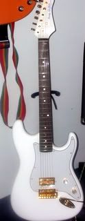 Still not a very good photo, the flash washed out the trem arm, making it look disconnected. Looks real nice and shiny "in the flesh", however. I'm happy with the look of the build- but looks count for doodly if it doesn't work. So the teardown begins. During which, the 'ol DMM shows N coil at 5.85KΩ. S Coil is 5.97K. So those values seem reasonable and I'm doubting a pup problem. However, the pot is indeed a 1MΩ. I need better glasses I guess. So I'll replace that with a 500K, and also replace the funky rotary switch- basically starting over for all practical purposes.  But I'm thinking (I know, "a little knowledge is a dangerous thing . . .") that the 1M pot still doesn't explain the low output. I rhought that would just make it really bright sounding, and reduce the usable "travel" on the knob. |
|
|
|
Post by newey on Mar 26, 2008 19:21:41 GMT -5
So, I got the new rotary switch in and I'm ready to (re)start wiring. But this rotary switch is substantially different from the one I had and I'm not sure how the connections go. It's a 3P 4 position rotary switch, but unlike the prior one, all the connections are on a single layer. It has 3 center terminals (labelled A, B and C) and 12 terminals in a ring around the outside, numbered 1-12. The switch is a sealed unit so I can't tell which of these are internally connected.
My original switch had 2 layers, but this project only uses the one layer- but the correspondence of the lugs was obvious on the other switch, being 1, 2, 3, 4 on one side and 4,3,2,1 on the opposite side.
How do I translate the switch wiring scheme to the new switch? I assume I'll be using only A and B out of the 3 center lugs (I assume these are the commons). Would A correspond to 1-4 and B with 5-8?
I used the word "assume" way too many times in the prior sentence for my comfort level in wiring this, and after bolluxing it up once already, I'm resolved to get it right this time. So any help would be appreciated.
I also ordered a couple of 500K pots, but I clicked on the wrong ones and got the linear taper ones by mistake. My temptation is to keep 'em and use one in this build, they're very nice sealed Honeywell pots, the action on them feels much smoother than the run of the mill pots I've used before. But I know the linear taper isn't optimal for guitar use. Are they so far off that I should bite the bullet and return them? Repacking, etc will probably eat up more of my time than the things cost anyway.
BTW, ordered all this from Allied Electronics and can't say enough about their service. Placed the order Saturday and chose the UPS ground shipping which was estimated at 5-7 days, got an immediate email confirmation of the order, got another email notifying me of shipment on Easter Sunday, and they arrived today, 3 business days later! Highly recommended based on my one experience with this supplier!
|
|
|
|
Post by ChrisK on Mar 26, 2008 19:50:27 GMT -5
So? Ok, here it comes. Since there isn't mention of a part number (with which one could search the manufacturer's web site for information), or a picture (with which one could possibly discern things, or see a part number (with which one could search the manufacturer's web site for information)), the great ChrisKarnak is having some difficulty "seeing" just what that there switch "is" (in the true meaning of what the meaning of the word "is" is). The switch is just like a clock with 12 hour positions (1 to 12), but with three synchronized hour hands (A, B, and C). Each one gets to point to 4 unique sequential hours. I would recommend that you use your multi-meter to measure the contact connections in each position. Write it down and post it along with a pic of the switch. If you want a time optimization, measure for just one pole (A, B, or C). The other two will repeat the sequence since low technology is afoot here (While you were ordering it from Allied's web site, did you notice any click-able areas that said "data sheet"?) |
|
|
|
Post by newey on Mar 26, 2008 21:07:48 GMT -5
Chris-
I detect a hint of sarcasm in your post- well deserved as it turns out! (I need the Homer Simpson "Doh!" smiley inserted here)
Yes, I saw the data sheet, but didn't realize it went on and on- I didn't scroll down past the physical data part. I see now that you can custom-order these things with internal connections as desired- but I just got the basic one as I didn't see the options further down the data sheet.
It is a C&K product, mfr part # A30415RNZQ. I took a photo but not too helpful- I would need a digital SLR with macro to get the details visible. But continuity is as follows, per my DMM.
In Switch Position 1, Common Lug A connects to lug 1, B connects to 5, C connects to 9.
In Switch Position 2, A connects to 2, B connects to 6, C connects to 10
In Switch position 3, A connects to 3, B connects to 7, C connects to 11
In switch position 4, A coonects to 4, B connects to 8, C connects to 12.
(I tried to make that into a table but couldn't figure out the table functions on the board here)
So I think I can translate that to my diagram and I'll post same so someone can double check my idiocy. All in all, a lot simpler than it looked at first blush.
|
|
|
|
Post by sumgai on Mar 26, 2008 21:51:53 GMT -5
Chris, That's because the envelope you held up to your turban was made in China, not India! Ge-fooey on you!  |
|
|
|
Post by ChrisK on Mar 27, 2008 11:51:47 GMT -5
Nah, the envelope just wasn't.
|
|
|
|
Post by ChrisK on Mar 27, 2008 11:59:40 GMT -5
Nah, me neither. I tried for aboot 15 seconds.......oh shiny!  Position 1; A connects to 1, B connects to 5, C connects to 9. Position 2; A connects to 2, B connects to 6, C connects to 10. Position 3; A connects to 3, B connects to 7, C connects to 11. Position 4; A connects to 4, B connects to 8, C connects to 12. www.ittcannon.com/media/pdf/catalogs/Leaf/SW_rotary_a.pdf |
|
|
|
Post by sumgai on Mar 27, 2008 14:50:45 GMT -5
OOOOOOOOH! Really shiny! | Position | Pole "A" | Pole "B" | Pole "C" | 1 | 1 | 5 | 9 | 2 | 2 | 6 | 10 | 3 | 3 | 7 | 11 | 4 | 4 | 8 | 12 |
All done with the three Table commands in the second row of tags, and the center command in the first row. It took about 1 minute, once I figured out the most brief but still informative layout. ;D HTH sumgai |
|
|
|
Post by ChrisK on Mar 27, 2008 16:00:01 GMT -5
Sooooooooooo,
What he's saying, but not showing (but wait, as a Mobile Gladiator I have that there secret all-post editing button) is this:
{table}
{tr}{td} Position {/td}{td} Pole "A" {/td}{td} Pole "B" {/td}{td} Pole "C" {/td}{/tr}
{tr}{td}{center}1{/center}{/td}
{td}{center}1{/center}{/td}
{td}{center}5{/center}{/td}
{td}{center}9{/center}{/td}{/tr}
{tr}{td}{center}2{/center}{/td}
{td}{center}2{/center}{/td}
{td}{center}6{/center}{/td}
{td}{center}10{/center}{/td}{/tr}
{tr}{td}{center}3{/center}{/td}
{td}{center}3{/center}{/td}
{td}{center}7{/center}{/td}
{td}{center}11{/center}{/td}{/tr}
{tr}{td}{center}4{/center}{/td}
{td}{center}4{/center}{/td}
{td}{center}8{/center}{/td}
{td}{center}12{/center}{/td}{/tr}
{/table}
Of course, all "{" get replaced with "[" and all "}" with "]".
;D ;D ;D ;D ;D ;D
Man, that's a good one!
|
|
|
|
Post by newey on Mar 27, 2008 18:01:22 GMT -5
Well, it was brief but not informative enough for me- as the prior postings in this thread show it took me a while to get the gol-durn "Ω" symbol to display properly.
So maybe the last couple of posts should be copied to the "Forum- related Info" section so all can reference the table technique.
And thanks again for all the help with this-
|
|
|
|
Post by newey on Mar 27, 2008 19:00:03 GMT -5
And I now get this, which should give me the same configs as before: 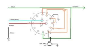 Which is a bad image, hard to read, don't know why that didn't upload to photobucket properly. JohnH originally suggested that I should do something with all those extra lugs, but I can't imagine what I would do since all 4 positions on the switch are accounted for. |
|
|
|
Post by sumgai on Mar 28, 2008 10:51:57 GMT -5
newey, Your latest incarnation is actually better, the hanging hot has been eliminated. I'd also say that you could try that linear pot, and see what you think. I personally prefer that taper in my guitar, but I am in the vast minority on that one. ;D HTH sumgai |
|
|
|
Post by JohnH on Mar 28, 2008 13:46:31 GMT -5
I also like linear pots for volume controls - they seems to be much better for making a small controllable reduction in volume (which is ALL I am prepared to do if asked to turn down).
However, if I'm also doing a treble bleed cap and parallel resistor, then I find that this is better with a log pot because the resistor tends to reduce the initial volume drop from 10, making a log pot feel more like a linear one.
John
|
|
|
|
Post by newey on Mar 28, 2008 17:18:46 GMT -5
Thanks, guys-
Wiring it up tonight, hopefully playing it tomorrow! I'll leave off the treble circuit for now, see how it goes w/o it, one less wiring variable in the mix.
|
|
|
|
Post by ChrisK on Mar 28, 2008 23:24:02 GMT -5
Yeah, but only for two of the poles!
?Switching in different tone caps for each position?
|
|
|
|
Post by newey on Mar 29, 2008 5:56:31 GMT -5
Hmmm . . . For now, I think I'll stick with the plan here for 2 reasons. First, this isn't a particularly hot pickup, as my measurements would indicate, so I'm not sure attenuating the signal further would be desirable. And, as a practical matter, I've got space issues around the switch.
The previous switch was longer, and I had to hog out some wood to get it to fit. But the contacts were to the side. This one is shorter, and before i started wiring last night, I thought, should be no problem fitment-wise, but the contacts on this one come out the bottom. I found after I got it all wired up that mounting it in the guitar, I'm crushing some of the wiring against the bottom of the cavity, particularly the cap at position #3. So I'm still troubleshooting here, gonna have to move that cap away from the switch with a length of wire I believe.
This started out to be a fairly straight-forward project, or so I thought going in, but my decision to use the rotary switch has been problematic to say the least. If I've learned anything (actually I've learned quite a lot), I would advise other nutz out there to carefully measure your cavity and a rotary switch before undertaking anything like this. I didn't, and I'm paying for it now.
|
|
|
|
Post by ashcatlt on Mar 29, 2008 12:25:40 GMT -5
do your knobs fit?
|
|
|
|
Post by newey on Mar 29, 2008 12:33:34 GMT -5
The knobs fit fine after some drilling out with a 1/4" bit. Holding the knobs with a visegrips while drilling wasn't optimal, so a decent bench vise has been added to the list of tools I need- the list grows longer all the time . . .  |
|
|
|
Post by newey on Mar 30, 2008 15:30:39 GMT -5
ARRRG! More problems!
About ready to call this project a failure and rethink the whole premise. After spending a large chunk of the weekend troubleshooting and rewiring, I finally got all 4 positions working per the "tap test", with the pickguard sitting loose in place over the cavity for testing.
But when I screw the guard down, I lose positions 3 and 4 on the switch. Just not enough depth for the rotary switch plus the wiring, and I don't dare hog out any more wood. Tried little pieces of electrical tape around all the connections, but still have the same problem once the guard is fully installed.
Also a grounding issue- gobs of hum until I touch the jack plate, then it goes dead quiet. Tried switching the jack connections, didn't help. So I figure I'm going to have to unbutton it once again and trace the ground wire back to the other end, must be a problem at the star ground.
Anyway, after all this I'm fairly certain I'm not going to be happy with the results even if I do get it sorted properly. The single coil sound off this HB is very weak and not really usable, and the HB positions, both series and parallel, are extemely bright and jangly. That's kind of what I was shooting for but this may be too much of a good thing, I think I'm going to have to add a tone control w/ a pretty good sized cap to knock that back a bit.
So. it's all coming back apart again for about the 4th time in the past 2 days, and I'm rethinking what I want to do totally.
This thread has been a lot longer than it ever needed to be, and I want to thank everyone who has helped out with this. But at some point one just has to conclude that it won't work and move on.
|
|
|
|
Post by sumgai on Mar 30, 2008 16:16:17 GMT -5
newey, If you insert the "guts" into the body, and it works as it lays there, not yet tightened down, that's a good sign. If it goes haywire when you tighten it down, then there are only two things that you can do about it. You've already tried using electrical tape to insulate the wires from the shielding, if I understood you correctly, but you also keep harping on the fact that there's not enough wood left to hog out, to make room for the wires below the switch. OK.......... tell us, what happens if the "guts" are sitting out on the bench, and you manually imitate the action of tightening down the screws? IOW, press on the back of the switch (and wires) with your thumb, holding the top of the switch either with your fingers, or laying that against the bench? Do positions 3 & 4 go south, or are they still operating? (Yes, I'm assuming that you can use one hand for this, the other one will be handling the screwdriver-on-pup test.) If that produces undesired results, like no sound when pressed, then you need to look closely at the switch itself, and/or the soldering job on the terminals...... sometimes things look good, but you never know when Mr. Murphy is standing just behind you............ Just a guess here, but can you bend the terminals to be "flatter", and maybe re-route the wiring? One more thing......... You said that the Hb configuration sounds bright and jangly, and that the SC config sounds weak. I don't think you've got it wired correctly, it seems to me as if those descriptions are inverted - an SC should be bright and jangly, and an Hb should be muddy, though stronger. Perhaps you've put one coil out-of-phase with the other? In fact, how sure are you of the color codes for that pup? Maybe it's time to double-check, with a multimeter?  HTH sumgai |
|
|
|
Post by newey on Mar 30, 2008 16:36:28 GMT -5
Oh, we've become intimately acquainted over the past two days. He's around so much, I might as well put him on the payroll . . . Thanks for the bench test suggestion, I'll give it a try when i pull it all apart again. I have tried bending the problem terminals a bit but perhaps more could be done. And I'll check the wiring colors again, you may be right about the SC. But the resistance of either coil alone was fairly low, so I thought I got what I got there. |
|


 Looks like it's time to explore the by-ways and backroads of my wallet, and see if the budget can withstand a hit that's not G.A.S. related.........


