bpdude
Apprentice Shielder

Posts: 26
Likes: 0
|
Post by bpdude on Feb 12, 2008 18:36:44 GMT -5
I'm doing things according to RJB's drawing, without the capacitors before the pickup buffer inputs. Are those very improtant? The power supply is a 9 volt battery. By 0V I mean the negative side of the battery.
One end of the selected pickup coils go to the input of the opamp. Where does the other end go?
|
|
|
|
Post by sumgai on Feb 13, 2008 4:31:59 GMT -5
bp, Per your message above, the other side of the pup will go to the same point as the battery's negative lead.... aka 'the ground'.  (Glad you answered that way, your original schematic would have taken me twice as long to explain. :  The two capacitors that connect to the op-amp's input (positive) terminal are there to prevent microcurrents that may leak out of the op-amp from getting back into the signal source, in this case, your pickups. I'd drop them, cause the pups are nothing but giant coils, well able to withstand, and repel, any current likely to come sneaking out the front door (the op-amp input).  Not to mention, they affect the tone, however small that effect might be. Why have 'em, if you don't need 'em. HTH sumgai |
|
bpdude
Apprentice Shielder
Posts: 26
Likes: 0
|
Post by bpdude on Feb 14, 2008 19:24:22 GMT -5
Ok, so the first version is done, and I've fitted it inside the guitar, except for the tone pots.
Bad news is that it's completely silent. The only thing I can get are pops when I throw the switches (both the pickup switches and the phase switch)
I'm looking through the circuit, maybe I missed something.
Does any of you have an idea what I could've done rong?
|
|
|
|
Post by RJB on Feb 14, 2008 19:43:25 GMT -5
OK I looked at the circuit again. And first thing I just checked. In my rush to get the schematic drawn and posted during lunch, I swapped +Vcc & -Vcc pins 4 and 11. That would definitely make it not work. Unfortunately it probably kilt the opamp as well. -1 Karma for me  When all is hooked up right the output pins should be sitting at 1/2 battery with no input signal. |
|
bpdude
Apprentice Shielder
Posts: 26
Likes: 0
|
Post by bpdude on Feb 15, 2008 6:42:18 GMT -5
That's alright, I substituted the circuit with two TL082's and I connected the positive and negative supply according to the spec.
Yet right now I'm suspecting that the chips might be damaged, so I'm going to buy a couple of opamps.
|
|
bpdude
Apprentice Shielder
Posts: 26
Likes: 0
|
Post by bpdude on Feb 16, 2008 14:13:28 GMT -5
Here's an update:
I manually checked the pickups -- that is, I turned off the circuit, grabbed a jack plug that was connected to my amp, touched the tip to the output of the pickup (non-inverting input of the preamp) while touching a ground point with my pinky finger -- and concluded that both pickups worked fine, and the switches are wired OK. The sounds that I got were very different in nature, just what I was expecting from this configuration.
The thing still doesn't work however.
I poked a voltmeter to a few places on the preamp, and the results are quite strange, not at all what RJB predicted (other end of the voltmeter was connected to the negative terminal of the battery, results were the same for both of the pickup preamps)
Output of the pickup (non-inverting input): about 0.1V (doesn't change if I pick the strings)
Output of the TL082: 8.1V
I bypassed the fourth opamp the way it was suggested by numerous sites on the net, and that one is working normally, the output is about half of the battery voltage.
I'll try to learn how to simulate circuits now with TINA/PSpice, maybe I will find out how can I make this work.
Every comment deeply appreciated!
|
|
bpdude
Apprentice Shielder
Posts: 26
Likes: 0
|
Post by bpdude on Feb 16, 2008 19:29:00 GMT -5
I solved the problem. I just had to connect the pickup's "negative output" to the 4.5V point, and now everything works fine. I'm not going to try to describe the sound. I'm afraid that right now I'm a bit biased emotionally Let me just say that I like it a lot. Now, I didn't connect the tone pot yet. I changed my mind and I won't drill another hole into the body, so there will be only one pot. Let me ask something: Now that there's no tone pot or anything else in the way of the pickup, isn't it feeding a 10 12Ω load? |
|
|
|
Post by sumgai on Feb 17, 2008 16:22:03 GMT -5
bippy, Congratulations! How did you arrive at that load figure?  sumgai |
|
bpdude
Apprentice Shielder
Posts: 26
Likes: 0
|
Post by bpdude on Feb 17, 2008 17:46:05 GMT -5
TL082 spec:
Features:
...
High input impedance: 1012Ω
|
|
|
|
Post by sumgai on Feb 18, 2008 0:15:39 GMT -5
bippy,
I was afraid you'd say that.......
Keep in mind that this figure is for open-loop circuits. As soon as you add even one resistor in either the input or the feedback paths, you reduce that number to something more realistic, like on the order of 103 to 106Ω.
All of which boils down to, no, the pup won't misbehave just because it's seeing a load impedance much higher than what it puts out. In fact, the higher the ratio the better, for a stronger and more uniform transfer function.
HTH
sumgai
|
|
|
|
Post by RJB on Feb 18, 2008 10:41:41 GMT -5
I see the nature of the problem. By eliminating the input caps, and tying pickup- to Battery 0v, the DC bias on the noninverting input was "shorted" to 0V. So with respect to the inverting input at 4.5V this would put the output at rail, and you would need an audio signal in the 4V range to move it off that rail.
The way you have it with the pickup- on 4.5v works because with battery power everything effectively "floats". The only concern I would have is if the pickup- is also connected to anything meta i.e. pickup cans or bridge "ground". This might introduce hum or a slight shock hazard. If we're talking about open coil pickups then we're fine.
|
|
bpdude
Apprentice Shielder
Posts: 26
Likes: 0
|
Post by bpdude on Feb 20, 2008 11:25:51 GMT -5
I think I can call the guitar stage ready. The 9v battery is fixed by a neodymium magnet that I glued into the cavity. The switches work, and they keep an even volume between pickup modes (though it's a cheap switch and I have to avoid pushing it between the positions because it somehow goes into hard overdrive when I do) The mix knob serves absolutely well, the volume is very even at every position, except when the phase switch is thrown of course. I can get amazing sounds by playing with the phase switch and the mix pot. You'll hear what I mean. And the overall sound is simply out of this world. Even the series positions are a lot brighter, livelier then before. This was recorded direct through the line input of my onboard AC'97 sound card, no effect added. www.mediafire.com/?5du99y9ylx0And this is the guitar through a tube amp (a 32 bit tube amp  ) www.mediafire.com/?22znljw2x2y(I had some problems with the cable here, never mind that) |
|
bpdude
Apprentice Shielder
Posts: 26
Likes: 0
|
Post by bpdude on Feb 21, 2008 11:06:44 GMT -5
bippy, I was afraid you'd say that....... Keep in mind that this figure is for open-loop circuits. As soon as you add even one resistor in either the input or the feedback paths, you reduce that number to something more realistic, like on the order of 10 3 to 10 6Ω. All of which boils down to, no, the pup won't misbehave just because it's seeing a load impedance much higher than what it puts out. In fact, the higher the ratio the better, for a stronger and more uniform transfer function. HTH sumgai I'm not an expert and I might be doing something wrong, but this is what I get from TINA (screenshot was cropped and rearranged to fit better) The ohmmeter is in the position of the pickup: 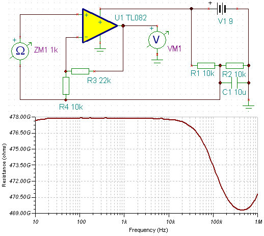 |
|
|
|
Post by sumgai on Feb 21, 2008 16:46:42 GMT -5
bp,
Call me dense, but what's that "xxx.xxG" business on the left side of the chart? Is that supposed to be some form of electrical unit multiplier (like k = kilo and m = mega)?
sumgai
|
|
bpdude
Apprentice Shielder
Posts: 26
Likes: 0
|
Post by bpdude on Feb 21, 2008 17:12:53 GMT -5
It insists that it's in gigs: 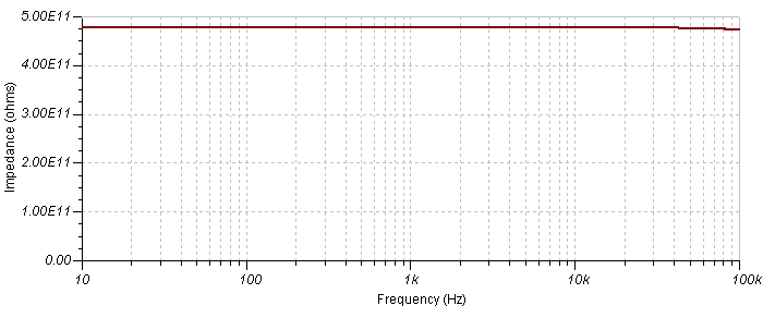 |
|
|
|
Post by RJB on Feb 21, 2008 19:31:03 GMT -5
Input/Output impedances can't be measured directly. The classic way is to apply a constant voltage to the input through a variable resistor. When the voltage across the resistor equals 1/2 the input voltage the variable resistor is equal to the input impedance. This is not practical in real life, because most measuring devices have a lower impedance than the circuit you're trying to measure.
In simulation you could do this, or feed a constant amplitude voltage source through a 10M-100M resistor into the input, and shunt the input with an equal value resistor. With ohms law and the difference between the expected 1/2 voltage and the actual measured voltage, you can calculate the impedance across the swept frequencies. Tedious, but the only way to really do it.
|
|
bpdude
Apprentice Shielder
Posts: 26
Likes: 0
|
Post by bpdude on Feb 22, 2008 7:56:44 GMT -5
Thanks RJB, that really cleared things up.
Just as sumgai said, these values simply wouldn't be realistic. I'm just trying to find out what's making the guitar sound so freaking great, even compared to the same positions that I used before the modification.
Here's a fun thing: I placed a small earbud headphone over the pickup, connected the guitar to an instrument input going to the PC and played a logarithmic sine sweep through this loop with a program called Room EQ Wizard, that showed me the transfer characteristic of this loop from analyzing the sweep.
I did this to the neck pickup before the modification and I got a mountain-like curve with a peak at about 3.2kHz, dropping in both directions. (I call this the pickups "Headphone response", not to confuse it with anything scientific)
After the modification the same peak occurs at 7.2kHz in series mode, and doesn't change much in parallel/single modes. The curves are a bit different, but the peak is about the same frequency.
|
|
|
|
Post by JohnH on Feb 22, 2008 15:03:25 GMT -5
bpdude - what you describe is exactly what you'd expect from a good buffer circuit. The reason is that the pickups are seeing just the high impedance input of your preamp, without being influenced by the capacitance of a guitar cord to the amp. You get a higher clearer top end, and the peak is associated with the small capacitances around the pickup rather than the larger one of the guitar cord. I find this too, with my one stage JFET buffers.
btw, well done on getting your circuit together, and great clips too. I also really like the idea of your transfer function tester. +1 to you.
John
|
|


 (Glad you answered that way, your original schematic would have taken me twice as long to explain. :
 Not to mention, they affect the tone, however small that effect might be. Why have 'em, if you don't need 'em.


 )
)
