iant412
Rookie Solder Flinger

Posts: 14
Likes: 0
|
Post by iant412 on Jan 21, 2008 22:15:44 GMT -5
So I have my guitar wired up, it sounds great. I was planning on putting in a ModBoard, but decided not to. So I have an extra hole in my guitar.
The guitar is a hollow strat body from Warmoth...it has an incredible amount of bass to it. More so than any other hollowbody that I have owned.
I've done some searching & couldn't find anyway to create a bass tone control without an eq of some sort.
Am I wrong? Is there a way to control the amount of bass in the tone?
|
|
|
|
Post by kuzi16 on Jan 21, 2008 22:28:45 GMT -5
are you looking for another knob? as in a volume, tone, and bass cut?
or just less bass out of the tone over all ?
|
|
iant412
Rookie Solder Flinger
Posts: 14
Likes: 0
|
Post by iant412 on Jan 22, 2008 20:10:20 GMT -5
I am looking for a bass cut control.
I have an extra spot for a knob, or I could use a concentric knob to control Treble Tone & Bass Tone.
|
|
|
|
Post by JohnH on Jan 22, 2008 21:07:57 GMT -5
Why not ry feeding the signal through a small cap, with the pot in parallel with it to bypass it. The extra parts sre in the hot line, ie no grounded lugs. Youd have pickups, then treble tone control, then new cap/pot, then volume control. Not sure what would be the best value cap, but probably in the range 2nF to 5nF. When the pot is at 10, it would fully bypass the new cap, giving full bass, while with bass control pot at 0, the signal has to force its way through the cap which will suppress the low frequencies.
John
|
|
|
|
Post by kuzi16 on Jan 22, 2008 21:34:25 GMT -5
is this what you are talking about:
the the hot wire goes to the center lug and runs out of the third lug. bridging the two lugs would be the cap. ( the cap value i think i was looking at was very small... maybe .003uf or something along those lines. ill have to look up in my notes and get back to you on that one. )
much like a tone control, couldnt this lower the volume as well as the frequency desired? can a resistor fix this? what type/value resistor would be needed if so?
im sorry to kinda thread jack but what iant412 is asking about is something that i was seriously looking at as well. I hope my questions help him as well.
|
|
|
|
Post by ashcatlt on Jan 23, 2008 0:05:19 GMT -5
John, you're freaking me out! Remember this thread?If I'm reading it correct you yourself "proved" via Pspice that it doesn't work quite so well without the third lug grounded, or at least partway with a resistor so it doesn't go all the way off. Fobits then went on to actually make one, was disappointed with the results, and ended up going to an active circuit. |
|
|
|
Post by JohnH on Jan 23, 2008 3:11:44 GMT -5
John, you're freaking me out! Remember this thread?If I'm reading it correct you yourself "proved" via Pspice that it doesn't work quite so well without the third lug grounded, or at least partway with a resistor so it doesn't go all the way off. Fobits then went on to actually make one, was disappointed with the results, and ended up going to an active circuit. Thanks, Id forgotten about that thread. That does seem to be the best we have on this subject! One difference with what I said earlier in this thread though, is that Im suggesting to put the bass cut parts before the volume control. That will work better with the ungrounded version than what I modelled before, since the vol pot will be providing some grounding. John |
|
ian412
Rookie Solder Flinger
Posts: 2
Likes: 0
|
Post by ian412 on Jan 27, 2008 0:15:58 GMT -5
Thanks for all the help so far.
Has anyone had any luck with one of these?
|
|
|
|
Post by ChrisK on Jan 27, 2008 1:49:13 GMT -5
|
|
|
|
Post by ashcatlt on Jan 27, 2008 23:18:30 GMT -5
That's the picture i was googling for a week or so while this thread languished! Does it actually work as intended? How extreme is the bass cut? Does it get that "Wish you were here" thing going, or is it more subtle than that?
|
|
|
|
Post by ChrisK on Jan 27, 2008 23:21:30 GMT -5
G&L sure seem to like it! Modeling is the pSpice of life! It's your turn.  |
|
|
|
Post by kuzi16 on Jan 28, 2008 8:06:01 GMT -5
thats almost the exact diagram I have for the guitar I'm designing right now. the only difference is that its Gibson style vol/tone/bass cut. yup... 6 pots. actually ill have stacked pots for the tone/bass cut. and i plan on using the .003uf ceramic caps. ill set it up like that and see how it goes. if there is too much volume lost... well i guess ill cross that bridge when i get to it. as far as "does it work as intended?" yes. ...and no. i have a guitar with a mod in the spirit of this one. Its on a switch. Switch it one way and it runs as a "normal" guitar would. switch it the other way and the hot is running through two 0.01 caps in series (i think... or is it 0.1uf? i cant remember). the pickups on the guitar are DiMarzio PAF pro (neck) and a DiMarzio Steve's Special (bridge) since the cap value isn't as small as it could(should) be all it ends up doing is taking off just a bit of the low end. ...almost to the point of sounding like a single coil minus the hum. I plan on "fixing" this later, but right now it isn't high on my "to do" list. a tiny amount of volume is lost but not enough that it has ever caused a problem. I'm my own worst critic and sound quality is something i strive for, so I noticed. My wife and friends (even those who play guitar) have not. i had hopes for a bigger change in tone, and in a way its my own damn fault that there isn't one. uh... beauty is in the ear of the beholder...  |
|
iant412
Rookie Solder Flinger
Posts: 14
Likes: 0
|
Post by iant412 on Feb 1, 2008 18:35:22 GMT -5
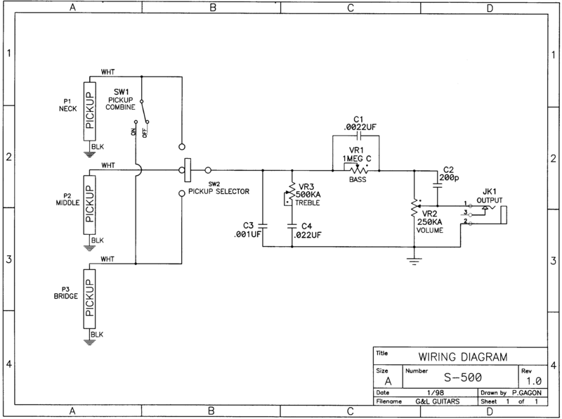
So I am not great with diagrams. How should I wire that together?
I am running two humbuckers through a 5 way super switch, then to treble tone & then volume.
It appears that I place the bass tone before the volume? There appears to be 4 capacitors, but I'm not exactly sure of the placement of them.
|
|
|
|
Post by ChrisK on Feb 1, 2008 18:55:53 GMT -5
Since the super switch comes before the tone and volume controls, its wiring (or even requirement) is beyond the scope of this discussion. C3 is not needed, and is used by G&L to make the pickups sound warmer! You apparently need to have the overall tone go the other way.  VR3 and C4 is the treble CUT circuit. It is fine where it is in the signal path. VR1 and C1 is the bass CUT circuit. It is fine where it is in the signal path. VR2 is of course, the volume, and C2 is the treble bypass cap that keeps the sound from going bland when the volume is turned down. The black dots on the diagram near the terminals on each pot indicate the clockwise terminal. Volume is full up when the wiper is at the dot terminal on VR2. Treble is full up (cut is at a minimum) when the wiper is at the dot terminal on VR3. Bass is full up (cut is at a minimum) when the wiper is at the dot terminal on VR1. As in this Fender schematic, on the tone pots (items 13 & 14), the terminals used are what should be used for a right-handed audio taper pot used for high or low frequency tone cut. The unused terminal on both is the clockwise one. In the G&L circuit, all three terminals are used on both tone pots. It was likely just convenient for them. Note that the end terminal connected to the wiper terminal on them has no effect since the wiper shorts out that part of the element. Since you initially indicated that you "have my guitar wired up, it sounds great", I'm presuming that you only need info on adding in the bass CUT control I discussed above. Therefore, you need to remove the connection from the output of the whatever pickup selector switch used and ensure that your existing high CUT tone control is connected to this switch output point, and add in the VR1 and C1 bass CUT circuit between this point and the clockwise terminal on the volume pot. The use of C2 is up to you. Done is. |
|
iant412
Rookie Solder Flinger
Posts: 14
Likes: 0
|
Post by iant412 on Feb 3, 2008 11:06:18 GMT -5
So the output from the selector switch goes into the bass cut. I'm still unclear of which terminal it goes to. The counterclockwise terminal? Then I attach C1 inbetween the two outside terminals, with a wire from the clockwise terminal continuing to the Treble Cut?
C1 is a capacitor
What is VR1, and what does 1 MEG C mean?
Thanks again for all of the help. Almost have this figured out!!
|
|
|
|
Post by pete12345 on Feb 4, 2008 11:49:14 GMT -5
VR1 is a potentiometer, like the volume and tone controls (VR stands for variable resistor) 1MEG denotes the resistance, in this case 1,000,000 ohms. (MEG=million) C tells you it is a clockwise audio (log) taper. Most log taper potentiometers are anticlockwise. So basically it works backwards compared to normal.
Hope this helps
Pete
|
|
iant412
Rookie Solder Flinger
Posts: 14
Likes: 0
|
Post by iant412 on Feb 4, 2008 22:02:18 GMT -5
Thanks Pete, it does.
So a normal pot will do the trick, however it just works in reverse?
Any answer on which wire goes to which terminal? (I asked this in my last post)
THanks
|
|
|
|
Post by ashcatlt on Feb 4, 2008 22:34:54 GMT -5
The black dots on the diagram near the terminals on each pot indicate the clockwise terminal. Of course, that doesn't tell us if we're supposed to be looking at the shaft or the bottom... This ![]() makes more sense to me. |
|
|
|
Post by ChrisK on Feb 5, 2008 0:01:06 GMT -5
|
|
iant412
Rookie Solder Flinger
Posts: 14
Likes: 0
|
Post by iant412 on Feb 19, 2008 23:43:18 GMT -5
Thanks for all of the help.
Hopefully I can wire this up this weekend & let you all know how it sounds.
|
|
iant412
Rookie Solder Flinger
Posts: 14
Likes: 0
|
Post by iant412 on Feb 23, 2008 18:03:33 GMT -5
I am completely comfused. I have the bass & treble tones wired up, however the bass cut has two points of high levels of bass, at either end of the pot.
When turned completely clockwise or counterclockwise the output is full bass. Only in the middle is the bass cut.
I have the capacitor soldered to the two outside terminals, the wire from the pickups on the middle terminal & the wire to the volume on the clockwise terminal (as indicated in the diagram).
Am I missing something?
/edit
Yes, I have been to StewMac & looked at all of the info. As stated before, I had the guitar wired & functioning. I'm having trouble understanding the diagram. Perhaps, my tone control isn't wired the same as the G&L diagram's tone control, and I'm not seeing that since I can't get the diagram figured out.
My main question with the diagram is with the variable resistors. On VR2 (the volume control) I see 3 wires, and I'm pretty sure I have that wire correctly, middle terminal to jack, clockwise terminal from tone controls, other outside terminal to ground. What about VR1 & VR3? There are two wires, and one continues in to the middle terminal. Does this mean that I attach a wire from an outside terminal to the middle? This is my point of confusion. ashcatlt's diagram helped me to understand which is the clockwise terminal, but the tone controls seem to be giving me problems.
|
|
|
|
Post by ashcatlt on Mar 3, 2008 2:08:01 GMT -5
Boy, I didn't notice you'd posted to this thread.
Sorry about that.
Did you figure it out? That's how they draw a rheostat (as opposed to a voltage divder, as in the volume pot). On the bass cut, connecting a wire between the CCW lug and the wiper will work, but you don't really need the CCW lug at all.
|
|