|
|
Post by UnklMickey on Jan 8, 2007 17:15:14 GMT -5
A Little History:
For quite some time, there has been interest in Brian May’s signature tones. While the sources of those tones are varied, one part of the equation is his guitar, its pickups, and HOW they are wired. Brian’s “Red Special” has 3 single-coil pickups. Each has its own phase switch, and on-off switch. (All are SLIDE switches) All of these pickups are wired in SERIES, rather than the conventional parallel method we are so familiar with. Wiring in series requires a bit more “housekeeping” than parallel. Instead of just disconnecting an unused pickup, we must also short its place within the series chain, or the other pickups will have no continuity. Obviously, DPDT switches would be necessary for the phase switches, but...Many reports suggest that Brian's on-off switches were merely SPST. This would mean, any unused coil, would need to be shunted.   I’d like I’d like to think he used DPDTs for both the phase and on/off switches.   In either case, this does make possible some sounds that are not possible in a conventional wiring scheme. However, it lacks the parallel sounds that most of us are accustomed to. (Someone should do something about that.) In addition, Brian’s wiring requires 6 separate switches to control 3 coils. Streamlining: There would naturally be interest in reducing the switch count. WD Music / Kent Armstrong has a unique 4-pole 3-position switch, having 2 poles on-off-on and 2 poles on-on-on. This is likely not exactly the same as the wiring suggested by Kent Armstrong, but the wiring shown below, would be be the functional equivalent:   This is “clean”. But, the switches are expensive ($20), and only available through WD Music. Is a special switch the only way to do this?Not willing ignore a challenge, I successfully devised a way to achieve the same result with a conventional 4-pole on-on-on.   And, of course, since this came from your favorite unkl, you know this is clean. You should expect to save a few pennies on these switches, as they are more common. But, make no mistake, they still aren’t cheap. Maximum Efficiency: Enter, our own ChrisK. Chris devised a method that uses 2-pole on-on-on switches. 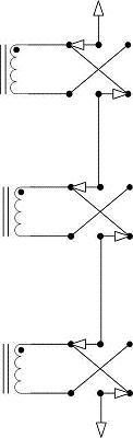  Nice. This is slightly less clean, than the Kent Armstrong version. No pickups are shunted. But, unused pickups do hang from hot. All-in-all, this is a great choice, for anyone concerned about the price of the switches. That's nice, but I want more: Another approach has been, rather than to reduce the switch count, expand the capability of the wiring scheme. The thought is to add parallel combinations, as well as series. Unfortunately, the existing housekeeping requirement of series wiring is compounded by combining it with parallel. Poor attention to detail has resulted in almost all of the designs I have seen, providing disappointing results. In addition to minor issues like shunted coils and coils hanging from hot, there are more serious problems, such as “partially parallel”, location-specific combinations, and my favorite -- dead-spots. (numerous dis-allowed switch combinations.) Fortunately, ChrisK has provided us with another nice creation -- the SSS ToggleCaster. While it does have a few limitations, and does not exactly follow the “one switch per pickup” concept, it is close enough to warrant mentioning here. And it is a nice piece of work. guitarnuts2.proboards45.com/index.cgi?board=schem&action=display&thread=1153502513 Never being one to leave any stone unturned, I decided to try my hand at one of these designs. I’ll discuss the evolution of this idea, and the results, on the next post of this thread… (Noted: edited by JohnH 20/01/2010 to restore diagrams - I left Unks links to his photobucket account also)
|
|
|
|
Post by UnklMickey on Jan 8, 2007 17:15:45 GMT -5
The Challenge:Although the Brian May wiring is strictly series, and has separate On/Off and Phase switches for each pickup, it seems any multiple pickup design that has separate switches for each pickup, and has series as well as parallel switching gets dubbed with the Brian May moniker. Unfortunately most (maybe all?) of the designs that include both series and parallel are flawed.... .....they have dis-allowed positions (dead-spots) in addition most have coils hanging from hot, and/or shunted coils, and/or an open circuit for all-off as well. Not long after joining GuitarNuts2, I set out to clean up one of those dismal failures, a “ladder” type circuit, where each pickup maintained it’s relative position within the structure, but when in “parallel”, it was only partially in parallel (with the pickups below it). After much fussing with a doomed idea, I chose to start with a fresh sheet of paper. The Evolution of a New Idea:We want to have one switch for each pickup, to decide whether the pickup is in-parallel, in-series, or off. So, how about if we create 2 GROUPS. One parallel, the other series. A pickup could be assigned to either group or remain off. Its position within the series group would be shorted, if the pickup was not present. For the parallel group, excluding a pickup would simply mean disconnecting it. Now, what shall we do with the 2 groups? We could simply select one or the other, depending on majority rule, based on the selection(s) made by the switches. This would mean mixed combinations would not be possible. I thought we would want to have both groups always available. Now to decide how to connect the 2 Groups together. If we put the Groups in Series with each other, any disparity between pickups (say 1 selected as parallel, another selected in series) would result in the pickups being in series with each other. I call this SERIES DOMINANT because the selection of series “trumps” the one being selected as parallel. Further, if 1 is selected as series, and 2 as parallel, all 3 are in series. When we select 2 as parallel, and 1 as series, things get interesting! The result is the first 2 ARE in parallel with each other, and the 3rd is in series with that PAIR. This is important to note, because the only logic that will occur in this is where parallel is the first operation and series is the second operation. aka Parallel first. While we’re on this version, we should also discuss the “housekeeping” tasks. To make things work properly, we need to, in addition to the “local” series tasks, shunt the Parallel group, unless at least one pickup is selected as parallel. This will give us a nice quiet all-off condition, and provide continuity for any all-series selections. Now let’s discuss the other possibility – putting the 2 groups in Parallel with each other. The selection of Parallel now trumps series, and Series-first is the only logic operation that can occur. Housekeeping is a bit different here. The parallel group is always connected to the output. We would only connect the series group if a pickup is selected in series. OR if ALL pickups are off. Although there is the limitation of “singular logic” within these two structures, they can effortlessly be expanded to as many coils as desired.  BACK TO LOCAL NEWS: BACK TO LOCAL NEWS:I tried imagining the whole picture all at once, moving the coil from group to group, and doing all the housekeeping too. It was simply too much to keep track of. After a while, I decided the best approach would be to concentrate first on moving the coil, next, doing the local housekeeping, and finally doing the global housekeeping. Placing the Coil: The first thought was to connect the coil to the poles, since it needs to move. In addition to the problems shown, the coil is bridged across the groups in the off position………….HORRIBLE!   Below we see what happens when an additional pole is attached to get rid of the bridging, the only remaining correct pole is not available for local housekeeping.   I finally make a move in the right direction. I put the series + on the upper pole. Doing this allows me to shunt the series group when parallel or off are selected. All I need now is to connect the coil + to the parallel +, when parallel is selected.   Now I add the connection from the coil to the original pole.   The remaining pole on the bottom is only correct for the housekeeping for the Series Dominant scheme.   Now we are ready to tie the whole thing together. the switches on the left are DPDT on-on for Phase. the switches on the right are 4PDT on-on-on for Series/Off/Parallel.   So, what will (and won't) it do?: So, what will (and won't) it do?:00 - All-Off 01 - Neck 02 - Middle 03 - Bridge 04 - Neck + Middle 05 - Neck + Bridge 06 - Middle + Bridge 07 - Neck + Middle + Bridge 08 - Neck * Middle 09 - Neck * Bridge 10 - Middle * Bridge 11 - Neck * Middle * Bridge 12 - (Neck + Middle) * Bridge 13 - (Neck + Bridge) * Middle 14 - (Middle + Bridge) * Neck And, of course, the OoP permutations of the above. Before you ask: there are 27 possible combinations of 3, 3-position switches. Above there are only 15. What happened to the other 12? Since this is Series Dominant, if Neck is selected as parallel, and Middle is selected as series (it doesn't make sense to say 2 pickups are in series and in parallel), the result is Neck * Middle. You can see that there will be redundancies. But as long as you understand the "rules" there will be no surprises. there are 3 mixed combos, that it WON'T do: A - (Neck * Middle) + Bridge B - (Neck * Bridge ) + Middle C - (Middle * Bridge ) + Neck If you select any of the above, there is no pickup in agreement with the one that is selected in parallel. Therefore, you get all 3 in series. This is NOT a wiring error. One of the phase switches could be omitted, but I think the operation is simpler, by having them all. This design can be reduced for 2 pickups, but that would be ridiculous! There are much simpler ways of doing series and parallel combinations for 2 pickups. This design can also be expanded to as many pickups as you want. This could be a very useful design for 4 or 5 pickups. (Edited by JohnH 20/01/2010 to restore diagrams)
|
|
|
|
Post by UnklMickey on Jan 8, 2007 17:16:11 GMT -5
(coming soon)
The Final Chapter -- Beyond Mini-toggles:
|
|
|
|
Post by ChrisK on Jan 10, 2007 17:30:19 GMT -5
I did a switch use case analysis, will PM results.
|
|
|
|
Post by ChrisK on Jan 10, 2007 18:04:31 GMT -5
No, I may well have missed something since I "guessed" on the actual switching config (me loves puzzles, especially cross-number ones).
I didn't include the phase switches in my analysis since they are completely unrelated to the effort afoot.
|
|
|
|
Post by UnklMickey on Jan 26, 2007 18:22:04 GMT -5
okay guys,
i just finished the second post in the "trilogy".
let me know how it reads.
thanks,
unk
|
|
|
|
Post by borsanova on Jan 26, 2007 20:14:24 GMT -5
Great reading, really instructing. Are you a teacher? Hey, this post gained me my second star! Now I'm a junior member!  |
|
|
|
Post by UnklMickey on Jan 26, 2007 21:38:21 GMT -5
i'm not a teacher by trade, but i have had to conduct a few technical training sessions.
i was going for a tutorial approach to this. i think the way i solved some of the problems, might be more useful, than the solutions themselves.
thanks,
unk
|
|
|
|
Post by JohnH on Jan 27, 2007 6:36:34 GMT -5
Nice one Unk - a valuable unsight into how to think through a wiring problem- or any design problem.
I think there are two ways .
One is the convergent analytical approach, which solves a solvable problem.
The other is divergent, based on random ideas, finding things that work in unexpected ways, or setting a new problem. This can be brain-storming. Don't think too hard, just put together parts and ideas at random - in our case, perhaps doodles of switches and wires, based on 'what do I get if I do 'This'. Don't evaluate them until you have put them down. Then change back to analyst mode and see what you have invented. Chuck out 99 ideas that are rubbish and keep one gem, that you would never have found if you had tried hard to find it.
John
|
|
|
|
Post by ChrisK on Mar 19, 2007 17:09:07 GMT -5
I agree completely. There is another dimension in the matrix in that schemes are micro or macro based. Unk took the tack of defining a micro cell, a module or "subroutine" if you will. When I did the SSS ToggleCaster and the RotoCaster, I took the shortcut of not caring about M*(B+N) in both cases and M+(B*N) in the former. I also took the tack of mirroring the designs about an "imaginary line" through the center of the middle pickup since only half the thought (and hence work) was needed. This explains my apparent "fascination" with hanging coils (lazy is). Taking unk's module-based scalable structure, I was easily able to map it from 4PDT center-on (DP3T) switches to rotary switches (and hence lever switches), and then to add additional poles to realize ALL possible single, parallel, series, and series/parallel combinations of three coils. Unk's scheme requires a 4-pole 3-way rotary switch per coil. While a 4-pole 3-way lever switch is not available, a 4-pole 3-way rotary switch can be had for under $5. www.digikey.com/scripts/DkSearch/dksus.dll?Detail?Ref=398748&Row=548162&Site=USIf phasing is included, 3 4-pole 5-way switches are required. Both lever (superswitch) and rotary (Grayhill) are suitable and will cost $20 each. www.digikey.com/scripts/DkSearch/dksus.dll?Detail?Ref=411984&Row=616485&Site=USwww.stewmac.com/The ALL combo mode requires a 7-pole 3-way rotary for the top and bottom (bridge and neck) coils and an 8-pole 3-way rotary for the middle (middle ;D) coil. The extra pole on the top and bottom coil switches could well be used for tone control parameter modification (caps, resistors, etc). Grayhill 8-pole 3-way rotary switches are possible, but are not generally available thru electronic distributors. A minor wiring change was made to unk's structure to easily add positions (ways) to realize integrated phase changes as well. The full structure requires a 7-pole 5-way rotary for the top and bottom (bridge and neck) coils and an 8-pole 5-way rotary for the middle coil. i37.photobucket.com/albums/e84/cekikta/Wiring/71BD30-04-1-AJN2071BD30-02-2-AJN.jpgThis can also be implemented with 3 Gunter switches (8-pole 5-way lever). ANY way, this is a $90 (Grayhill rotary) to $120 (Gunter) proposition just for the three switches (the 8-pole 5-way ones). And then, you get to wire it! Heh, heh, I found a use fer these after all: 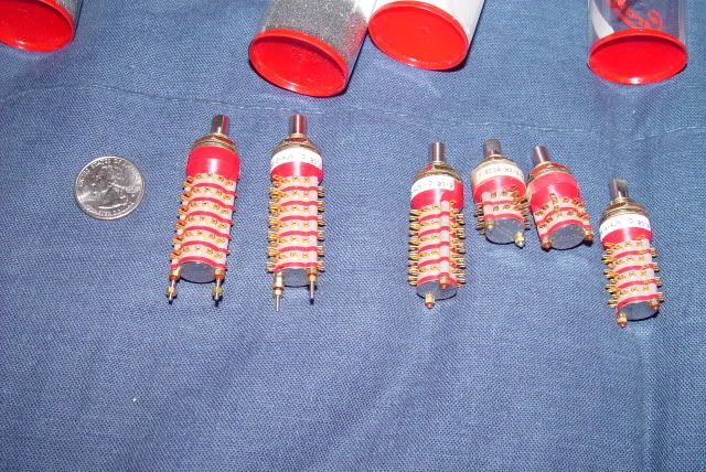 I did develop a much easier way of doing this a few years back (2002). A$$uming that the phase switches are separate from the combo switches, it takes three SPDT center off switches, a GAL (a ultra-low standby current/input threshold activated CMOS Generic Array Logic IC), 8 SPST analog switches, a few resistors, an optional OPAMP buffer, a voltage regulator, and oh yeah, a 9 volt battery. I'd also included active tone controls. Note that I'd also included CMOS switching of phase and humbucker splitting. BTW, it's only easier since you use a PCB to do the wiring, program the GAL to do the switching logic, and use active stuff to save a whole bunch of money. This can be done for about $20 to $30 in volume. i37.photobucket.com/albums/e84/cekikta/Wiring/P-CADCore2-Sheet5.jpg |
|
|
|
Post by ChrisK on Mar 31, 2007 22:58:55 GMT -5
BTW, I have found a source for the Grayhill 8P3T rotary for $12.
I also found a source for a 1" diameter 8P4T rotary for $12. This would enable the additional selection of electrical out of phase in either series (my choice) or parallel.
I have to determine the actual manufacturer's part number for both and determine the exact switch from their data sheets.
Both of these have gold plated contacts, which are ideal for ultra low-level switching such as in a passive guitar (no wetting current to speak of).
|
|
|
|
Post by ChrisK on Apr 22, 2008 20:12:04 GMT -5
Some further extrapolations: I'd shared these with unk last year (20070204), but never heard back from him on it. The Unk Brian May theme with ChrisK extrapolation20070204 The original design (“A”): 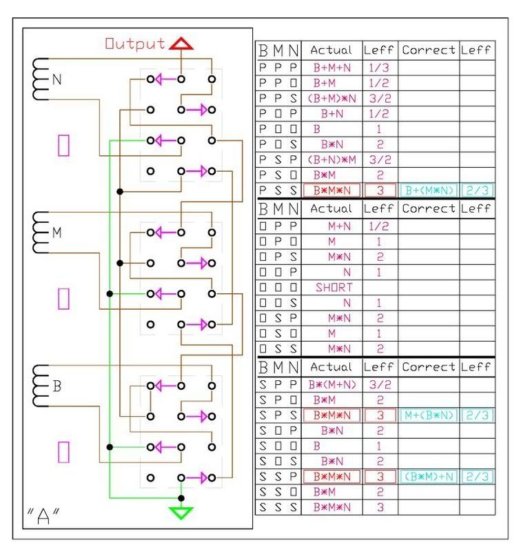 This was evaluated as per the attached test table in all switch combinations and found to have some issues (ChrisK) with B+(M*N), M+(B*N), AND N+(B*M). The combo’s returned B*M*N in all three cases, which result in a structure that has three times the nominal inductance and output level compared to one pickup alone. The alternate B+(M*N), M+(B*N), and N+(B*M) combinations result in a structure that has 2/3 times the nominal inductance and maybe 1 ½ times output level compared to one pickup alone. The difference in output level is 2:1, and the difference in inductance is 4.5:1. I think that these alternate combinations are needed. The pesky alternate combinations (“B”): 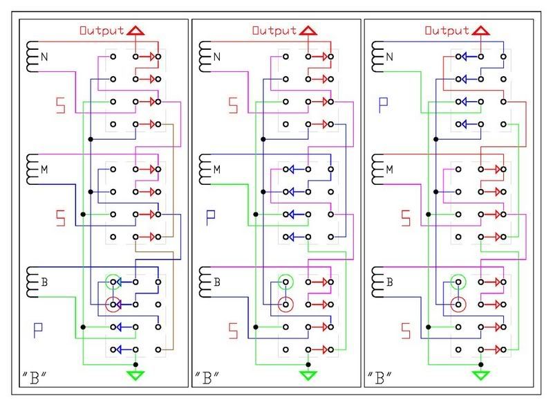 The red and green circles represent a “very minor epiphany”. In all three cases, if the red to green link wire was removed, and if the red node went to OUT and the green node went to COM, the alternate structures would occur. A simple DPDT switch could easily achieve this, with unfortunate really goofy results in other combinations. Remember, unk stipulated no inadvertent dead spots other than all pickups off. The solution to be discussed later…… Translation to a rotary switch (“C”): 4P3T 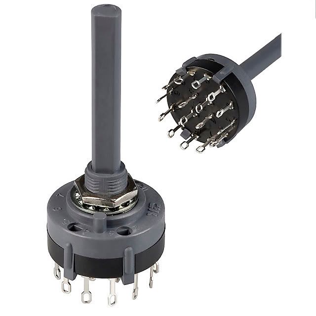 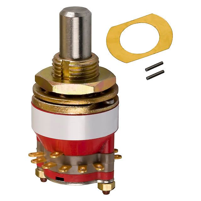 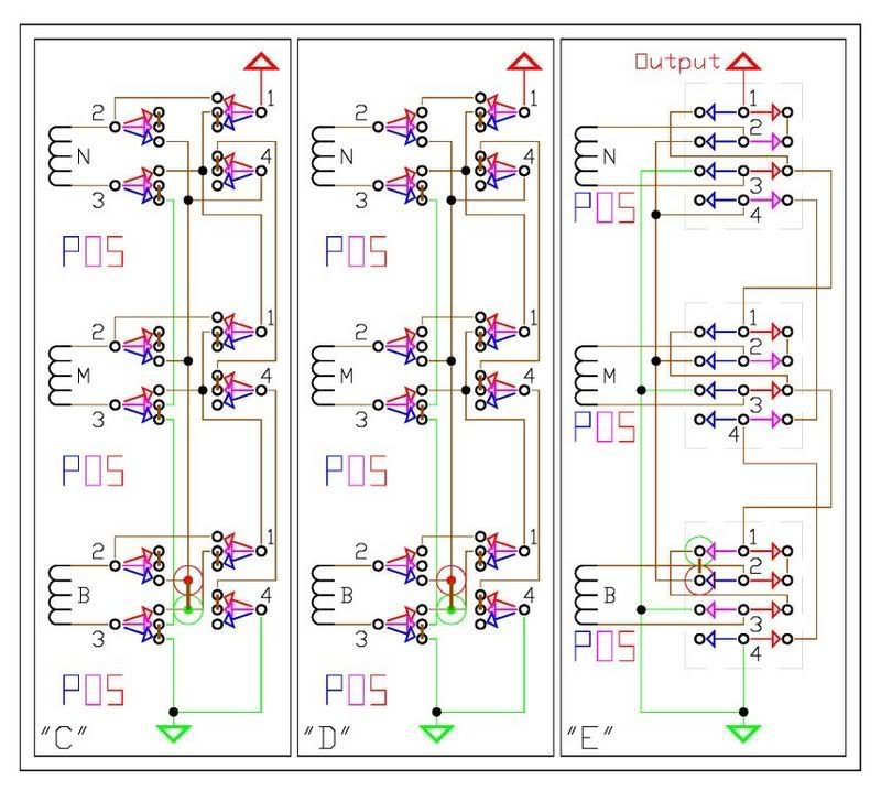 The thick jumper links on each pole mimic the switching of the 2P3T (4P3T) ON-ON-ON that unk used. The thick red to green link wire is as noted before. (“D”) shows a simple wire modification on poles 1 & 2 of each switch to permit each pickup’s wire to be the sole occupant of a pole wiper, AND to enable extrapolation to integral phase as well as structure on a single switch. (“E”) shows this mod applied to the 2P3T (4P3T) ON-ON-ON switches to permit each pickup’s wire to be the sole occupant of a pole wiper. This enables pickup replacement and lead swapping to be the easiest possible. Realizing the alternate combinations structure: 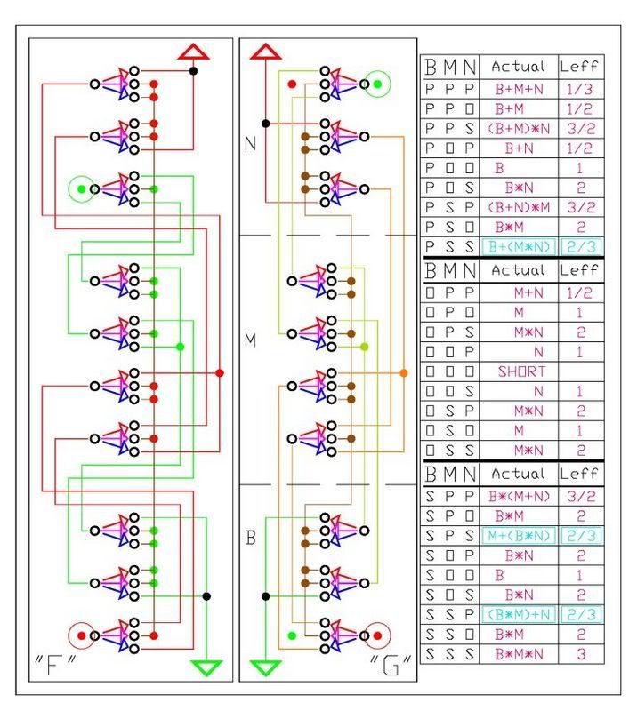 As I’ve mention in the past, correct series/parallel and parallel/series structures demand full attention to the state of all switches. While my ToggleCaster design had natural parallel across two in series, and fairly easy drive change for series driving two in parallel, it had two additional dead settings (either bridge or neck alone in series) and it didn’t address the M+(N*B) or M*(B+N) structures. guitarnuts2.proboards45.com/index.cgi?board=schem&action=display&thread=1153502513(“F”) shows the original development of the additional switch poles needed to realize the alternate B+(M*N), M+(B*N), and N+(B*M) combinations. (“G”) is the easy to read version. The attached test table shows that these alternate combinations are properly realized. Combining the alternate combinations structure with the rotary structure: 8P3T 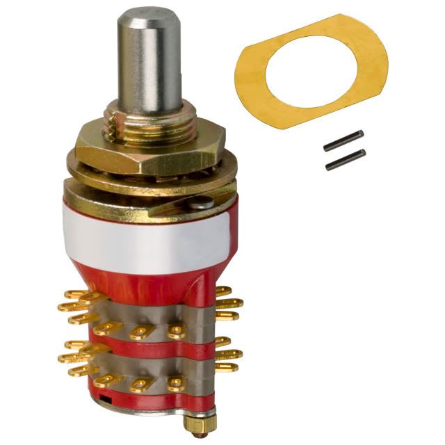 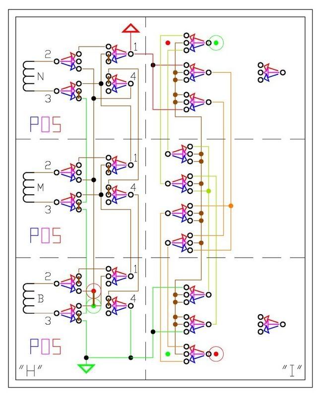 Note that to integrate the structure in (“I”) with (“H”) requires that the thick red to green jumper link in (“H”) be removed and the red circled node in (“I”) be connected to the red circled node in (“H”), and the green circled node in (“I”) be connected to the green circled node in (“H”). Note that while the middle pickup switch now requires 8 poles (similar to my findings while developing the RotoBucker guitarnuts2.proboards45.com/index.cgi?board=schem&action=display&thread=1153505234), the bridge and neck pickups only require 7 poles, freeing one each for perhaps tone control structure variation based on each pickup’s mode. Combining the alternate combinations structure with the rotary structure AND with phase:8P6T 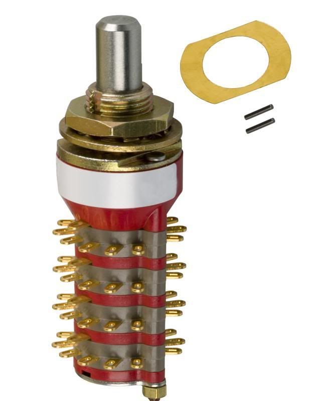 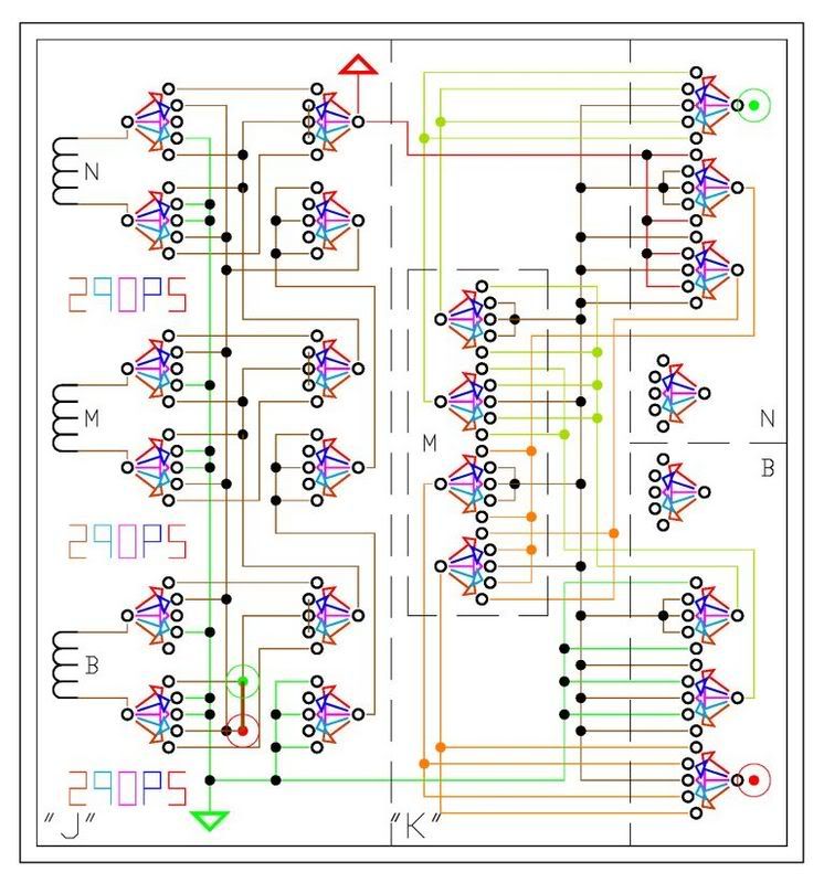 The same integration rules for (“H”) and (“I”) apply. Note that phase can be realized with a DPDT for each pickup that it is desired for without integrating it into the structure switches. A design for unk’s original structure would require 3 2P3T (4P3T) ON-ON-ON switches (or 3 4P3T rotary switches) and 2 or 3 DPDT switches for phasing. A design for unk’s original structure plus integral phase would require 3 4P6T (pinned to 5T) rotary switches (or 3 4P5T lever super switches). A design for unk’s original structure plus the alternate combinations would require 3 8P3T rotary switches and 2 or 3 DPDT switches for phasing. A design for unk’s original structure plus the alternate combinations plus integral phase would require 3 8P6T (pinned to 5T) rotary switches (or 3 8P5T lever Mega Switch “M” switches). 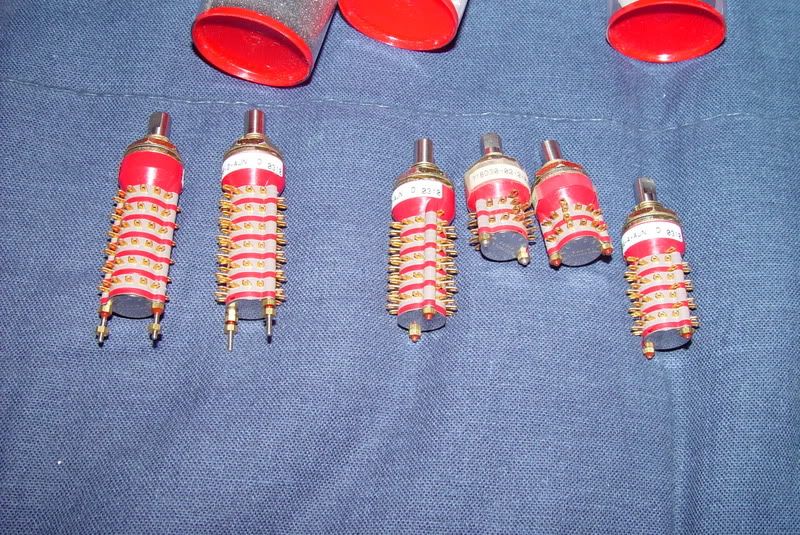 Switches Electroswitch 4P3T (C5P0403N-RA) PCB version ($8.40); rocky.digikey.com/WebLib/ElectroSwitch/Web%20Data/C5^C6%20Series.pdfAn eyelet variation (C5P0403N-A) ($10.00); rocky.digikey.com/WebLib/ElectroSwitch/Web%20photos/C5P0403N-A.jpgC&K 4P3T (A40315RNZQ) eyelet version ($6.52); rocky.digikey.com/WebLib/C&K%20Components/Web%20Data/A%20Series.pdfrocky.digikey.com/WebLib/ITT%20Cannon/Web%20photos/A40315RNZQ.jpgE Switch 4P3T (KC43A30.001NLS) eyelet version ($4.88); spec.e-switch.com/G-T/G510270B.pdfGrayhill Series 71 switches 4P6T (71BD30-02-2-AJN) ($20.77); lgrws01.grayhill.com/web/images/ProductImages/J-31-44.pdfrocky.digikey.com/WebLib/Grayhill/Web%20Photos/71BD30-02-1-AJN,%2071BD30-02-2-AJN.jpg Grayhill Series 71 switches 2P6T (71BD30-01-2-AJN) ($15.69); rocky.digikey.com/WebLib/Grayhill/Web%20Photos/71BD30-01-1-AJN,%2071BD30-01-2-AJN.jpg CEK Solution Spiel 20070204.doc |
|
|
|
Post by sumgai on Apr 23, 2008 12:07:43 GMT -5
Chris, I see the Side-Slap has rotated.... very cool! ;D And just between you, me and Fairchild, several 4066's could fit in the space of just one of those monstrosities.  Either of the remaining ones would provide ample room for a power source.......  sumgai |
|
|
|
Post by ChrisK on Apr 27, 2008 16:20:43 GMT -5
This actually is an old trail with an old destination. I've since refined it much further. One such encapsulation was the HSS All Mode Caster.But, it's even more refined and optimized than that now, with both a three-position version for external phase switching and a five-position with integral phase. The "burden" of switching the humbucker from series to parallel was too much, so I changed it to phasing only and will use an external pp pot for the humbucker series/parallel. Further optimization required only three poles for PSS correction, freeing up one pole per pickup for whatever. It is going into the walnut rear-routed body with three switches and four pp pots/knobs. As I posted a bit back;  Not much new under the sun (except the real low current consumption of mine from 2002). |
|
|
|
Post by newey on Apr 27, 2008 19:33:14 GMT -5
Chris- Please post some build photos. It sounds like it'll be both beautiful and appropriately guitar-nutty. |
|
|
|
Post by ChrisK on Apr 27, 2008 22:27:33 GMT -5
I'm planning to build the switch and pp pot assembly onto a precut brass or aluminum plate that mounts into the cavity. This way I can control the rotation (or prevention thereof) of all components without having to worry about the mounting nuts having to be so tight that they abrade the wood. It'll also be much easier to work on.
While I'm leaning toward creme chicken head knobs and creme Strat knobs to match the creme pickups, I still like the idea of gold lever knobs that form a continuous bar in the off position with Gold pot knobs. The bridge is a gold-plated recessed TOM with strings thru the body. I haven't resolved the look, so I haven't resolved the complete build.
|
|
NanooMan
Apprentice Shielder

Posts: 34
Likes: 0
|
Post by NanooMan on Sept 11, 2008 9:17:06 GMT -5
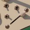
I'm happy to see other people interested in such a project. I'm building a guitar right now, and this is exactly what I have been trying to design. Here's what I came up with, but it includes the problems we originally found before with shunting and hanging coils.  That was assuming a switch with this sort of on/on/on configuration:  In fact, how do I tell the difference between slide switches with different configurations? Jordan |
|
NanooMan
Apprentice Shielder
Posts: 34
Likes: 0
|
Post by NanooMan on Sept 11, 2008 12:05:12 GMT -5
|
|
|
|
Post by ChrisK on Sept 17, 2008 17:08:11 GMT -5
NanooMan Glad to see that you're interested. Complete solution sets have existed for both a 3 throw version sans phase (+PARALLEL, OFF, +SERIES that uses three each of an 8P3T rotary switch) and a 5 throw version with phase (-PARALLEL, +PARALLEL, OFF, +SERIES, -SERIES that uses three each of an 8P5T rotary switch). I took unk's basic 4P3T Center-ON toggle switch version and extrapolated it to complete solutions with full positional inheritance from the other pickups sometime around Feb07. Here is the post for the The HSS All Mode 'Caster which implements the 5 throw design. I have further simplified it (well, as much/little as possible) but have not posted updates since there has been little interest in, or understanding of it other than by myself. I'm building a Strat copy with it, but have purposely gone quiet otherwise. BTW, the link that you've posted is for a volume OEM switch manufacturer in Hong Kong. They are not a supplier to end customers unless you want thousands of many part numbers. Also, these are printed circuit board mounted switches with very, very tiny posts a few millimeters apart. Additionally, I can't see your images, are you using photobucket or some other hosting site? |
|
rexx
Rookie Solder Flinger

Posts: 3
Likes: 0
|
Post by rexx on Jan 30, 2009 17:23:31 GMT -5
Q- Where can I purchase 4PDT on on on toggle switches? Has anyone successfully wired a 3 single coil guitar with a parallel/off/series pickup selector for each pickup?  |
|
|
|
Post by ChrisK on Jan 30, 2009 19:12:14 GMT -5
By our definition this would be a 4P3T Center-ON switch. These are also called 4PDT ON-ON-ON switches or DP3T (an extrapolation of the DPDT ON-ON-ON switch, which was originally called a SP3T switch since, with a wire jumper, was used to select one of three signal paths at a time). Confused? Well, we all are. These can be purchased from several places. I tend to buy from OEM electronics parts suppliers such as www.digikey.com and www.mouser.com , and not from suppliers focused on the guitar parts industry since they tend to significantly overcharge. You must download the data sheet for the one that you use as the switching progression seems to be different that the norm for the E-Switch unit (it's certainly different than the C&K units which I usually use). Yes. As you read this thread you will see that I have taken unk's original 4P3T cell and extrapolated it to all available topologies of 4 pole, 3 and 5 throw switches. Note that the 4P3T switch WILL NOT realize all possible combinations of three pickups (of which there are 18 sans phase including off). The B+(M*N), M+(B*N), and N+(B*M) are not realized. For each of these one gets B*M*N. To realize ALL possible combinations, one must use at least 7 pole switches. If you are willing to use the 8P3T rotary switch, I have a source for MilSpec parts (normally $87 each) for $12 each. This is about what the cheapest 4P3T toggle goes for. 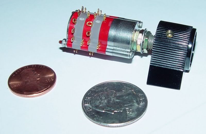 In other words, the complete solution set for all possible combinations of three coils exists. Also see the The HSS All Mode 'Caster for a design that includes phasing and a humbucker. |
|
rexx
Rookie Solder Flinger
Posts: 3
Likes: 0
|
Post by rexx on Jan 31, 2009 20:28:45 GMT -5
Thanks Chris, seems I was searching for the same switch by a different name. ie 4P3T center on I'm trying to customize my Squire strats 3 single coils with 3 series/off/parallel 4P3T center on toggles and 3 push pull pots for individual phase switching. Q- 500k ohm pots are better than 250k for monster series parallel strat mods? Q- Is it best to use 3 matching coils to achieve maximum 60 Hz hum cancellation? |
|
|
|
Post by newey on Jan 31, 2009 21:55:50 GMT -5
Rexx- Hello and Welcome! As it appears you have not yet been appropriately welcomed.  You should repost your questions as a separate thread in "Electronics and Wiring", you'll get quicker responses there. And we're wandering a bit here. |
|
|
|
Post by ChrisK on Feb 1, 2009 17:25:25 GMT -5
Good, this is a very flexible scheme. It is also very intuitive compared to most other complex schemes.
To be fair though, it is more complicated to "drive while playing" than schemes with fewer switches.
You don't need three phase switches. Reversing the phase of all pickups is the same as reversing the phase of no pickups. You actually need N-1 phase switches, where "N" is the number of pickups. In this case, two will do.
I would use a 500K for the volume since there may be three coils in series.
I would use 500K for the tone controls for the same reason.
Yes.
However, for best tonal diversity, it's best to use three dissimilar coils.
I have a similar subset scheme in a MIM Nashville Power Tele with a Mex Tele bridge pickup, a Mex Tele covered neck pickup, and a Mex Strat middle pickup. It gets superb tonal diversity, especially in series and series out of phase.
Q- 500k ohm pots are better than 250k for monster series parallel strat mods?
Q- Is it best to use 3 matching coils to achieve maximum 60 Hz hum cancellation?
|
|
rexx
Rookie Solder Flinger
Posts: 3
Likes: 0
|
Post by rexx on Apr 10, 2009 0:20:32 GMT -5
As a home studio project guitar this wiring has yielded many useful tones beyond the normal single coil combo. Thanx all!
I decided on using three in line toggle phase switches, its not needed to OOP every pickup BUT having
3 OOP switches
is a good visual memory setting thing.
I noticed some good noise cancellation tone settings with my 7 switch setup
(3x 3PDT & 3x phase + Interupt)
but they were far and few good settings
between the 60 hz hum selection sessions.
Solution:
Q- Could I replace my three single coils with three SD duckbuckers?
- Can the two individual duckbucker coils be wired so the phase switches function without noise?
i.e. Should I keep the shielded wires separate until post phase switches?
|
|
frobro808
Meter Reader 1st Class

Posts: 54
Likes: 0
|
Post by frobro808 on Nov 30, 2010 4:47:25 GMT -5
...holy crap
i feel like i just took the red pill
i now know that i truly know nothing
you people are gods amongst men... really
|
|


 Either of the remaining ones would provide ample room for a power source.......


