urthman
Rookie Solder Flinger

Posts: 4
Likes: 0
|
Post by urthman on May 28, 2008 15:27:32 GMT -5
It's a crap rendering - threw it together in CorelDRAW - an artiste I am not. And there's the other crap rendering I added to my page And there's the other crap rendering I added to my page I have some software around here somewhere that'll let me do this right - I just have to find it.
|
|
|
|
Post by D2o on May 28, 2008 16:03:10 GMT -5
|
|
|
|
Post by ChrisK on May 28, 2008 18:01:38 GMT -5
It doesn't, period.  The luxury of urthman's approach is that the Fender standard 3/5 way switch has a superfluous pole once one realizes that one is freed thru the use of a master tone (the marketed domain of many Squier's). In the Strat world, where ONLY ONE pickup is (well, was) EVER selected at ONE TIME (except fer that a'shortin' refiled/defiled w/ two extra "notches" [as in positions] 3-way ohmygoshitsnow 5-way [don't you just love how words run together in domain names?] that unintentionally selects two adjacent pickups; the extra pole can also select the exact same connectivity pattern as the "primary" (as in not grounded) side. In essence, both wires of the coil are selected/not selected, and the unselected are allowed to float aboot, neither contributing to the intentional signal nor to the "reception" of signals of ill intent from the "aether" coupled in thru common mode "sharing of the road" back to the amp. Since you want to actually advertently connect to TWO pickups at one time, you'll have to use one of these 4PDT ON-ON-ON switcherooski's.Just replicate the signal side switching (SSS) on the return side switching (ground, for those return-adverse). Of course, you'll be switching the shields on the pickups........................... Now, if you're willing to short the offending coils............your switch will work.  This type of stuff only works well with components that were specifically not designed to do it.  |
|
|
|
Post by D2o on May 28, 2008 22:32:47 GMT -5
Sounds like something Edison would have said!
Does it make any difference that there are only two antennae pick-m-ups in the T-15? Or is the switch you have indicated still a must?
|
|
|
|
Post by ChrisK on May 29, 2008 11:34:28 GMT -5
The issue is that the Fender 5-way switch does some "free shorting for you", which gives the B+M and M+N combinations using just one pole. Remember, it's really a "shorting" (as in make before break) two pole three position switch. Since it can now linger in the shorting "notches", something happens for free. If it didn't, you'd need a four pole switch (well, two poles for each connected coil/one pole per connected wire). Since you want to have both wires from your pickups switched, you'll need the one pole per wire for a total of four. Now, the Peavey pickups have a single conductor plus shield (we do all realize that this is two conductors ). To do the same thing, the shield must also be switched. However, if you don't want the shield to be removed from ground (urthman's nexus), but want to change its "loading coil"/coupling effect into the local ground, you could short the unused coil. The DPDT ON-ON-ON switch looks like this (bottom view):
Bridge Selected
..[B}
/|\../|\
[C]..[D]
[E]..[F]
Both Selected
..[B}
...../|\
[C]..[D]
\|/
[E]..[F]
Neck Selected
..[B}
[C]..[D]
\|/..\|/
[E]..[F]
goes to local ground
goes to output pot
[C] goes to neck pickup hot
[D] goes to bridge pickup hot
[E] goes to output pot
[F] goes to local ground
Both pickup shields go to local ground.
|
|
|
|
Post by D2o on May 29, 2008 12:39:04 GMT -5
Daft Function: adjective Etymology: Middle English dafte gentle, stupid; --------------------------------------------------------------------------------------------------- Chris ... I apologize in advance for being daft ... Here is what my 3 way looks like now (I think - going by memory right now, but I thnk this is it) EDIT - went home and looked ; here is the way it IS ... is is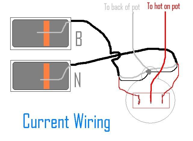 --------------------------------------------------------------------------------------------------- I'm really sorry that I am not clear on what you're telling me.  Can I use the 3 way? I am not sure what you mean by local ground (ground ring on 3 way? the other pole on the 3 way?), and where doe the hot wires go from the 3 way  ... is this what you mean? 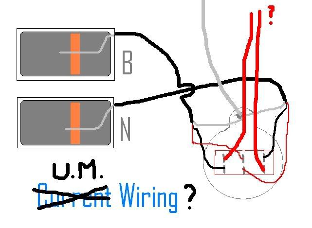 ---------------------------------------------------------------------------------------------------- Thanks for your patience, Chris |
|
|
|
Post by ChrisK on May 29, 2008 18:17:16 GMT -5
I edited my last post. I used words like local ground as part of the overall theme of modules and such approaches to wiring. If you want to emulate urthman's double sided switching method, you will need to also switch the shields. You will need a 4P3T ON-ON-ON switch. If you don't want to use a 4P3T ON-ON-ON switch, you can try shorting the unused pickup. This only requires a DP3T ON-ON-ON switch. I notice that your pickups have each grown a wire since your last drawing post. Now you have a RED, a BLACK, and a BARE?
|
|
|
|
Post by D2o on May 29, 2008 19:38:20 GMT -5
Well, I'm seriously considering getting a cheap strat so I can just do what urthman did.
By the way, is there anyone else here (not aimed at anyone in particular) who actually has a strat and would be willing to give this a whack?
Puberty ... they're older now.
"Well, they've been afraid of changing
cause they've built their life around two
But time makes you bolder
Pickups get older
Lines get to three, not two"
No, they were always in the drawing, but I noticed they were not well defined, and thought I'd better make them so as you had specifically mentioned two conductors.
|
|
|
|
Post by ashcatlt on May 29, 2008 22:41:47 GMT -5
I'm afraid it just ain't going to work with the switch you've got. The workings of that switch are completely counterintuitive to me, but ChrisK is definitely right. Go take a look at the Templates in the Schematics section. I'm very much afraid that if I open up my strat I'll never get it back together. Why do you think I haven't fixed the "kill switch" so that it actually shorts the output? That guitar is mostly immune to this issue. When any one pickup is off, it's shorted*. When the pickups are split I do still have one end or the other of the "unused" coil connected, but I'm thinking the humbucking action must still be in effect, no? *Seems to me some folks around here take issue with this practice, as well. Can't remember why. In my case it was the only way I could get any one pickup to shut up completely. But that's another story, I think. |
|
|
|
Post by D2o on May 30, 2008 8:42:03 GMT -5
yup, and this is putting a snag in the whole free aspect of trying out urthman's idea ... which I think is worth a try.
I will keep an eye on craigslist for something on the cheap, otherwise this (use of a non-strat guitar) is beginning to be a whole lot more involved and expensive than I had bargained for.
Aw, c'mon! ... kidding, I'm totally with you, actually.
I'm not sure. It sounds like it wouldn't normally be, except you have shorted it ... which may be doing the trick, if I am interpreting Chris' comments correctly.
|
|
|
|
Post by D2o on May 30, 2008 11:26:50 GMT -5
Okay - problem solved.
[/size]
This putrid guitar is the perfect candidate! I'll let you know what the outcome is.
|
|
|
|
Post by ashcatlt on May 30, 2008 15:20:38 GMT -5
Please remember that the results of your test will be extremely sensitive to a whole number of variables. If you're really looking for a scientific test, let's have some careful control of all of these. Like plug the amp into one outlet, use the same cabling, etc, for both before and after tests.
I'd suggest making the tests several times (different times of day and night) both before and after as well, since anything from a running refrigerator to a passing semi-truck could skew the results.
And record the tests if you can so we can hear and/or see them.
|
|
|
|
Post by D2o on May 30, 2008 15:39:44 GMT -5
Please remember that the results of your test will be extremely sensitive to a whole number of variables. If you're really looking for a scientific test, let's have some careful control of all of these. Like plug the amp into one outlet, use the same cabling, etc, for both before and after tests. I'd suggest making the tests several times (different times of day and night) both before and after as well, since anything from a running refrigerator to a passing semi-truck could skew the results. And record the tests if you can so we can hear and/or see them. Good suggestions, Ash. I was basically just going to record before and after, but I think I'll get a little more scientific. Have a nice weekend. |
|
urthman
Rookie Solder Flinger
Posts: 4
Likes: 0
|
Post by urthman on May 30, 2008 16:13:01 GMT -5
The ideal test should involve two (nearly) identical Strats (one wired for isolation and the other one stock) and another "nice" guitar with humbuckers - one phat-but-clean amp - and the worst offending club in your area - put each guitar through each switch position - hit a chord, zero your Vu, and then hold the strings and measure the noise floor - write it down. (Don't compare active monkey nutz to passive monkey nutz)
This would be the A-B-C acid test.
The problem with the home laboratory is that no one gigs in that environment - even my 'pudding' file was done in the home lab - the best test is in the all-too-noisy EM environment because that's where it's going to work or not - that's where it counts.
Don't be safe - be real! You test space ships in space - so test the axe on the wood - freakin' hurt me with that mother! To date, it has served me well!
|
|
|
|
Post by D2o on May 31, 2008 11:32:45 GMT -5
Okay, so this guitar does not have a Fender style 5 way switch. It is more like a picture of what someone at the "Tian Kin Lee Happy Business Enterprise Concern"s theory of what a 5 way switch might look like. NOTE THAT IT HAS ONLY SEVEN (7) POLES. It has 7 poles and a green PCB ... plus another part with a pole on either end, only one of which is being used ... it works just fine, but I don't know what to do with it. Does this look right? 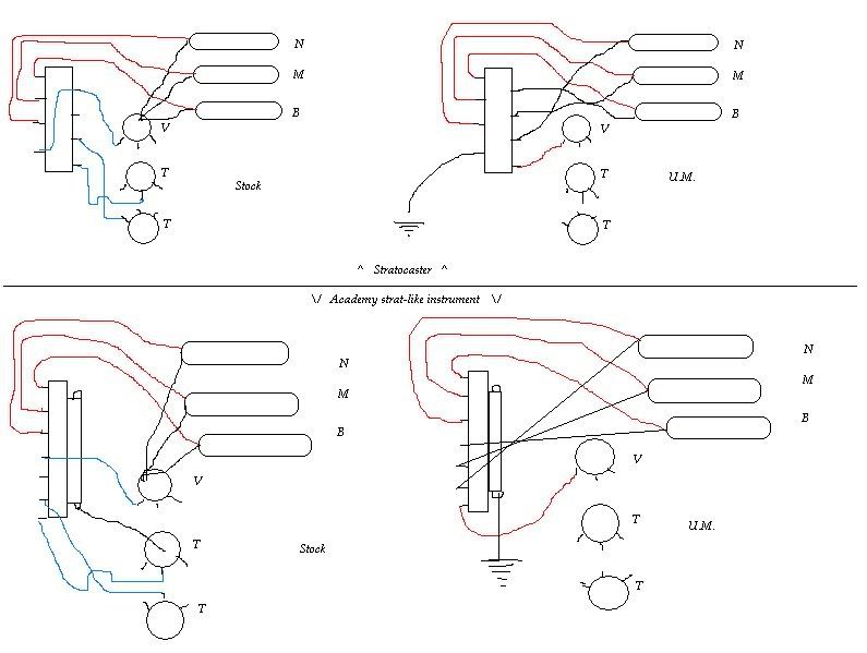 |
|
|
|
Post by ashcatlt on May 31, 2008 13:09:21 GMT -5
There's only 2 poles. Might be a total of 9* lugs, or terminals, but only 2 poles. You're gonna have to replace that switch, since you'll need all 8 terminals. That should be 3 throws on each of 2 poles, plus the common for each. One of them has been either or removed or designed out of what you've got. Otherwise, it's a standard "asian style" strat switch. Here's a link where we encounter one very similar. *Including the terminals on either side which are connected to the metal case of the switch, generally used for grounding the switch itself when it's not already in contact with a foil (or copper tape, etc) cavity shield. |
|
|
|
Post by D2o on May 31, 2008 15:01:09 GMT -5
You're gonna have to replace that switch, since you'll need all 8 terminals. That should be 3 throws on each of 2 poles, plus the common for each. One of them has been either or removed or designed out of what you've got.  Thanks, Ash.  Yes, this is one special instrument ..... Okay, I got the switch ... in for a penny ... I'll keep you posted. |
|
|
|
Post by D2o on May 31, 2008 16:49:22 GMT -5
Okay, guys - I need some wiring help. This isn't working - I've now got some hanging wires, and I am generally unclear on where all the wires are supposed to go using urthmans scenario ... Where does the wire that goes "out to VOL and TIP" actually go? Here is what I have now ... something isn't right, because it's not working. The pickups were reading B 7.08 M 6.94 N 6.88 (and about 3.5 in positions 2 and 4) ... now I am getting only one reading - 6.68 K ohms - in position 4. Help! 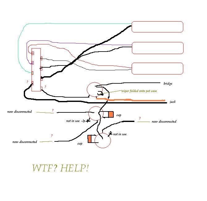 |
|
|
|
Post by sumgai on Jun 2, 2008 12:26:41 GMT -5
DD,
James Hetfield would say it thus: "Left side Goood! Right side Baaaad!"
The left side of your switch is OK, but the right side is offset by one. The question mark is at the wrong end, it should be at the top of the switch. Move all the pickup signal wires down one lug, and move the wire from the question mark to the top.
When that's working, then you can hook up one of the tone pots as Master Tone.
HTH
sumgai
|
|
|
|
Post by D2o on Jun 2, 2008 15:46:52 GMT -5
DD, James Hetfield would say it thus: "Left side Goood! Right side Baaaad!" The left side of your switch is OK, but the right side is offset by one. The question mark is at the wrong end, it should be at the top of the switch. Move all the pickup signal wires down one lug, and move the wire from the question mark to the top. When that's working, then you can hook up one of the tone pots as Master Tone. HTH sumgai Thanks, sumgai. I'm a combination of half thrown off by all of this new wiring, half in jeopardy of being banished by a wife who's wondering where the hell her husband has vanished to, and half enlightened by burning plastic and solder fumes. That's why my math is so good now.  So, a few more questions just to be safe: 1) is there a wrong way to install a 5 way switch - I have the spring on the outside farthest from the pots. 2) You say move the signal wires down one lug on the right down one. The wires coming off the pickups that are going to the right side (nearer the pots) are the ground wires. That is the same as signal, correct, or do I have everything bass-ackwards? 3) Is this how it should be? EDITED - I initially forgot to move the wires as described.Nhot ||||||||Hot (2) Mhot ||||||||Ngrd Bhot ||||||||Mgrd Grd (1) ||||||||Bgrd ||||(1) to output jack sleeve ||||||||||||(2) to wiper on volume and, finally, 4) How, exactly, do I hook up a tone pot as Master Tone? Thanks. DD |
|
|
|
Post by ChrisK on Jun 2, 2008 20:31:21 GMT -5
|
|
|
|
Post by D2o on Jun 7, 2008 7:39:50 GMT -5
Thanks, Chris. "Argh" is right! ... believe me ... - Just when I thought I was getting somewhere ... So far, - I have tried urthmans instructions ... (A) (B) (C) (D) =============== xx(E) (F) (G) (H) A = bridge signal return B = middle signal return C = neck signal return D = out to volume E = bridge hot F = middle hot G = neck hot H = out to ground ... nuttin' doin' - I have tried urthman's instructions, but with signal returns moved so that they are not on the poles ... nuttin' doin' (A) (B) (C) (D) =============== xx(E) (F) (G) (H) A = out to volume B = bridge signal return C = middle signal return D = neck signal return E = bridge hot F = middle hot G = neck hot H = out to ground ... nuttin' doin' - I have tried putting all three signal returns on (A) and trying to find a common terminal. I wasn't having much luck ... the best I could do was to run a jumper from (H) to (C) and run (C) to volume ... sound kinda familiar ... almost like a stock strat? Anyway, it didn't work either - I could only output in three positions. - I have tried connecting all three signal returns, and running three seperate wires from the three connected signal returns, with one of each being connected to (B), (C), and (D). The idea was that if each pickup was going to be connected all the time, there would have to be signal from all three no matter what position the 5 way switch was on. (A) (B) (C) (D) =============== xx(E) (F) (G) (H) A = out to volume B = b,m,n signal return C = b,m,n signal return D = b,m,n signal return E = bridge hot F = middle hot G = neck hot H = out to ground This was somewhat successful, in that there was output in all 5 positions. However, so far I have not been able to get the volume and tone worked out ... I just can't seem to get output through those controls. What I was able to do was just hook up directly from the switch to the patch cord and confirm that there was still the typical strat hum levels, i.e. Neck N+M Middle M+B Bridge Noisy Bucked Noisy Bucked Noisy Keep in mind that this is without volume and tone controls involved, which would throw things off. - I have performed many other combinations that I won't mention or have forgotten. How I have been doing these experiments is using insulated alligator clips on either end of a lead. In other words, it's very easy to try out any ideas you gents may have. Everyone interested, please give some thought to: - how the pickups should be connected - how the volume and tone should be connected - how the jack should be connected I ask because so far I can not reproduce utrhman's idea, nor can I get the volume and tone to cooperatively join in the fray. - urthman, if you've got your ears on: You've taken the time to write about this on your site and you've taken the time to post here in defense of your idea, which leads me to think that there must be something to your claim. However, I can't get it to work ... and not for lack of trying. There are glimmers of hope that it wants to work ... When you first posted, you wrote that you didn't really care what we thought and so you may decide to turn down my following request. But I do hope you will accept it. Would you consider going under the hood of your modified guitar and telling exactly where EVERYTHING goes (and I mean EVERY SINGLE WIRE). That way, I can duplicate exactly what you are talking about and get this thing up and running. Would you be willing to do that? - Thanks, everyone. |
|
|
|
Post by ChrisK on Jun 7, 2008 16:38:46 GMT -5
I gots to go somewhere now, but I will post exactly how to do this. In essence, youu will duplicate the switching functionality for the black wires from the pickups - mind the order, so that it will work and switch exactly like the signal outs from the pickups.
You're waaaaaaaaaaaaaaaaaay out in complexity space. You need many deep breaths and some good mental flossing.
|
|
|
|
Post by JohnH on Jun 7, 2008 17:47:31 GMT -5
Its a grey wet morning, a long weekend here in Oz, and I can't get out to enjoy my usual Sunday morning running around, and too early yet to blast the neighbourhood with heavily crunched riffage.
So I thought I'd start at the beginning and see what this thread is all about.
Synopsis: The assertion is made that it is better to disconnect pickups from ground as well as from hot? to avoid extra antennae-like noise entering the signal?
Well as with others here, I don't believe it. But it is hard to explain, and for those reading an explanation, hard to understand.
So how about just prove it for yourself?. The different wiring that is proposed involves disconnecting unused pickups from ground, to reduce noise. If that were effective, then conversely by connecting more and more unshielded wires, pickups and other electrical junk to ground, it ought to be possible to increase noise.
So try this, get a normal guitar, plug into an amp and turn up gain until you get some hum and buzz. Now get some wires, alligator clips, spare pickups, old TV sets, refrigerators (not plugged into mains!) and other scrap metal, connect them all together, and then attach them by an alligator clip to the outer grounded barrel of the guitar jack plug. The idea being to attach significantly more stuff to the ground of the circuit than just a pickup, to try to maximise any adverse effect. Is there any audible difference in buzz? If not, then the theory is disproved.
Now DD, you have a guitar that is not working. Theres nothing actually wrong with Urthmans wiring concept, in that it should work OK. Looking at your texted diagram, I think the problem could be the order and arrangement of switch lugs. Do you have a standard type Strat switch? If so, looking from the back of it, it would be
---A---B---C---D
E----F---G---H
A and H are the poles, but I think they are offset differently than your diagram, ie, A and H are closer to each other than E and D. So:
B, C, D are bridge, mid and neck hot respectively
E, F, G are bridge, mid and neck return
A goes to volume
H goes to jack ground
If you want standard tone controls on mid and neck, you could wire the neck tone pot and cap in series between D and G and the mid between C and F.
Or forget it all and just use a standard wiring diagram!
cheers
John
|
|
|
|
Post by ChrisK on Jun 7, 2008 23:25:38 GMT -5
Look at the picture. The Tele/Strat 2P3/5T switch. Look at the lower view which is a side view. The lever positions are marked 1/1&2/2/2&3/3. This enables the same picture to be used for both the 3-way and the 5-way (there is no 1&2 and 2&3 position on a 3-way, just the 1/2/3 positions). Look at the upper view of the switch. This shows the terminals coded for the connectivity as a function of the lever position. Obviously, when the lever is in the 2&3 position, each "P" pole common is connected to the respective 2 AND 3 terminals on the same side of the switch as that "P" pole common. One can also see that the switch is symmetrical as far as installation direction, normally the plate side faces the lower bout since not much is going on there anyway. However, if it's mounted on the outside of the pickguard, the wiring will be exposed and the lever will be somewhat more difficult to operate. Since you have the switch, and it's an OPEN FRAME switch (which means that one can look at the connectivity as it switches), one could also get one's digital multi-meter and measure its connectivity as well. In the traditional Strat wiring, one side of this switch selects pickup 1/1&2/2/2&3/3. urthman's approach is to ALSO select the pickup ground wires the same way. In other words, when pickup 1 is selected for its hot lead, the ground pole of the switch is selecting the pickup 1 respective ground lead to connect to, er, ground. It's just mirrored switching. 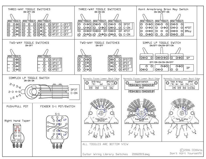 The issues that I have with the design are as follows: 1. In a standard Strat, normally at least one pickup is always grounded AND connected to the output. These pickups have an effective output impedance of under 10K. This will shunt a lot of the noise alluded to. I would expect more coupled noise if the hot leads were all connected to the output and only one/two grounds at a time were connected to ground (hanging coils). While I'm not dismissing the design out of hand, I do need to be convinced. 2. This is a Squier. An entry-level device meant to glean entry-level revenue while leaving substantial room for "encouragement" for an upgrade. These are specifically designed to not be especially good guitars. Now, while I realize that there can be exemplary examples of Squiers, I have also encountered exemplary examples of cantaloupe and grapes amidst lots tendered as generally pedestrian offerings. Statistically, a Squier is only just a Squier. If one thinks that one detect an elitist attitude, they're right. You don't always get a scalable increase in feature and quality when you pay more, but you generally, on average, get more. Did I mention that this was a Squier? On testing procedure; 1. Installing an urthman wiring scheme into one guitar and comparing it to an un-modified Strat/copy is NOT a TEST of the urthman wiring scheme. It's a test of two entirely different guitars. It's in the class of the high end audioflies testing where they compare pedestrian cables with pedestrian equipment to their Feldercables use with their Felderamps. While it isn't quite like comparing sex to a cobblestone, it isn't an apples to apples test either. 2. Now I know some tests were run in the past on the effect of shunted coils and possibly hanging coils. These tests were inconclusive (not proving a negative) in that they could never be conclusive. For such testing to be measurable, the effect (a hanging coil or a shunted coil) must be alternately rapidly switched in and out (1 second per mode) ON THE SAME note instance, since the struck/plucked note CANNOT be replicated anywhere near the precision needed. Even if they could, the recorded waveform traces cannot be correlated. 3. That was a clue. If you want to test the veracity of urthman's wiring ONLY (the ONLY point to the test), you must install the 5-way switch that switches the pickup hot leads like a standard Strat, you must install the switching of the respective pickups ground leads (respective meaning like for like for the selected position) to the second switch pole, AND (this is the important part), you MUST run the three pickup ground leads thru a 3PDT toggle switch that connects ALL THREE ground leads to the respective side of the 5-way to effect the urthman switching, OR connects ALL THREE ground leads to the internal ground simultaneously (like it's done in a standard Strat). Mount the 3PDT switch in the unused tone control hole. A 3PST can be used (but generally not found) to short each respective pickup ground lead wired to the grounding side of the 5-way switch, to the pole of the grounding side of the 5-way switch. Use a 3PDT this way, its easy, only four wires are needed. [Gee, I wonder what the effect was of a shared tone cap with all of this switching afoot? Was anyone watching what the pots were connected to?] 4. The 3PDT switch must be externally accessible so that the guitar can be in exactly the same orientation and position, at nearly the same instant, so that the A/B comparisons can be done on a second by second basis. This is for both quiet listening and struck string testing. We want the local conditions et. al. to be IDENTICAL or this IS NOT A TEST. 5. As far as the impact of ONLY the urthman mod, any test done with anything else is moot, and only a waste of time and typing. (The exercise will still be mental, but it won't be flossing......) |
|
|
|
Post by D2o on Jun 9, 2008 8:59:40 GMT -5
Thank you, John and Chris. John, You have a way of pointing things out that kinda come up and smack me up-side-da-head * - more on that in a minute - Chris, you kinda smack me up-side-da-head * ;D Thank you both for that *. EDIT - just in case this* could be taken the wrong way, the comment was intended in the most complimentary and appreciative manner possible.Yup, that's my thought ... and to be clear, I am trying to prove urthman right. I don't know if that is possible, due to both physics and my limited ability. Good idea - I haven't done it yet, but why not? I will hook up to the ductwork and plumbing of the house. Oh boy, this is starting badly.  I won't repeat the rest of it. But I will fess up to having made the biggest romper room boo boo I have made in a while ... and I make LOTS, so this is saying something! You know how the multimeter probes basically couldn't give a hoot what you attach to them ... hot to the black probe or whatever, nor do they get bent out of shape if the red probe is stuffed into COM one day and not the next. They just happily march along measuring stuff ... Well, er, I sorta forgot that I was bench testing and didn't pay as much attention as I would of if I was actually wiring. I was treating the hot as signal return and vice versa, so the multimeter said everything was okay, but it was no wonder it wouldn't work when I tried to include the pots into the mix. Things started to work out a lot better after you pointed that out. oopsh. shorry. By the way, I am using and after-market 5 way switch (Allparts, maybe - I don't recall) and ALL terminals/poles have the same spacing, fwiw. Chris, yes, sir. Did I mention I am testing an "Academy" strat-like instrument? Google that ... really. Nada. Apparently, I now own every one ever made - I don't get the whole keep it stock thing either. ;D I knew that, and if my brain was not switched off ... I am sorry about that ... ... well, I finally got it up and running, and there is no noticeable reduction in hum, regardless of which method I wire it (now successfully wire it). There is no increase in hum either - it doesn't seem to do anything, as far as I can tell so far. Mind you, I have not recorded the hum yet to actually look at the pictures - I will though. However, first I will try to get a 3PDT or 3PST, whichever I can find, and try the final piece of the puzzle. I really would love for this to work. I'd love to prove urthman right, as it's an easy mod for people ... you know, who aren't me.  Argh! Argh!reed, on both counts. I will do one other modification as well when everything else is done: shield. I'll post the results of that as well. |
|
|
|
Post by D2o on Jun 13, 2008 13:51:20 GMT -5
I have concluded my test of urthman's "silence of the strat" wiring modification. I tried to include the use of a 3PDT or 3PST switch in this test, and quickly remembered what a PITA it was last time I tried. Since it was not originally called for and substantially alters the ease of urthman's idea, I can justify leaving it out of the test. This test was performed under conditions that were as controlled as I could make them. I plugged the same guitar into the same amp, with the same patch cord, with the volume set at 6, every time, so that the test would be easily comparable and repeatable, and the hum would be clearly audible. The following tests were performed with the guitar being held in the same position, angle, distance, etc. every time. The purpose of this test was to prove urthman's assertion about unconnected pickups acting as antennae, if possible, and I assure you all that I did not veer from that goal. Urthman, I buggered up the wiring initially, which may have unneccessarily and unfairly caused some skepticism. I apologize for that - the fault was entirely my own. My conclusion is that there is a slight reduction in hum as a result of the urthman modification. It is not particularly noticeable to either the ear or the computer, but I don't think it is my imagination. In practical terms, however, I could not achieve the results you speak of - it is certainly not a sustantial or distinct reduction in hum, especially when compared to the final test - a stock guitar, but shielded - which produced a more noticeable reduction in hum. Disclosure: The pickguard was not screwed on for the first three parts of the picture below, but proper shielding required that it be screwed down for the final part. However I did compare it to a previous recording of the unshielded stock guitar, with the pickguard also on, and it also produced similarly less hum there as well (in other words, before shielding, there was no significant difference in hum whether the pickguard was on or off). 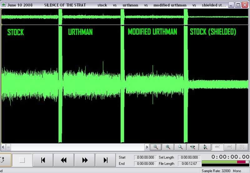 You can hear the signal comparison here - you may have to allow pop-ups in order to hear it: media.putfile.com/Stock-v-Urthman-v-Modified-Urthman-v-Shielded-StockBy the way, "modified" urthman is all three pickup signal returns going to ground side switch pole and then a seperate wire out to ground from each terminal on the ground side of the switch. As a secondary experiment, I attached two 30' stranded wires to each of the ductwork and plumbing, respectively, in my house. With the stock wiring, it picked up a mish-mash of broadcasted noise (several radio stations, I believe ... ). With the modified wiring, it still picked up the broadcasts, although it seemed to pick them up to a far lesser extent than with the stock wiring. It is important to note, however, that the change from stock to urthman wiring was not instantaneous, and by the time I got the modified wiring in place I could still hear broadcasted noise, but I was hearing talking instead of music, (would could account for it picking up "less" noise, if there was less to pick up). In fact, I did not control the part of the experiment involving the source or type of broadcasted noise in question, it could have been anything that caused that reduction in noise. Nevertheless, there was less noise being picked up at the time that I used the modified wiring, for whatever reason. 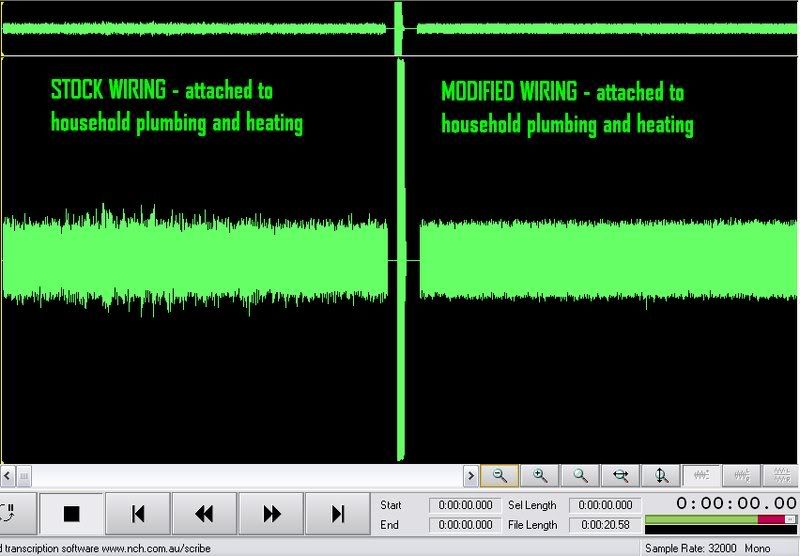 You can hear the signal comparison here - you may have to allow pop-ups in order to hear it: media.putfile.com/Stock-vs-Urthman-with-plumbing-and-heating-attached BOTTOM LINE:
If your guitar happens to be attached to a house, there may be some merit to urthman's idea, otherwise the "silence of the strat" modification did not deliver a material reduction in hum or other interference.
This could vary from guitar to guitar, etc., but shielding this guitar resulted in the least amount of hum. |
|
|
|
Post by JohnH on Jun 13, 2008 16:01:46 GMT -5
Hey dd, +1 to you for your energy and persistence. It shows that shielding is a good thing, and although we knew that, I have never seen a test with results for it presented before.
I just need to make a comment about the 'attaching to the house' tests. My thought in suggesting connecting large antennae-like objects to the guitar ground was to create a situation analagous. but much worse (if worse at all), than a pickup connected only to ground, ie the other end is free. Connecting to ductwork and particularly plumbing probably also connects to earth since those systems are grounded. Hence there can be extra ground loops created. Just a long free wire, not connected at the other end would suit the purpose.
cheers
John
|
|
|
|
Post by newey on Jun 13, 2008 19:46:47 GMT -5
Good Job, DD! John already gave you a +1 so I'll avoid "piling on", but well and truly deserved.
However, Urthman has left himself an "out":
So he is able to claim that you haven't truly performed the "acid test" if no dimmers, ceiling fans and/or flashing neon were included in your testing.
He seems to be claiming that the noise reduction he has is somehow more noticeable, or even objectively greater, in a particularly noxious setting. This makes no sense to me because one would think the reduction in noise would be proportional to the amount of noise extant in a given environment, and therefore that a modification which produces a big noise reduction in an EM nightmare environment ought still to show some noticeable effect in a lower noise setting.
So I see your testing as being valid, but Urthman could certainly claim otherwise- that the hum reduction by his system is only noticeable in particularly axe-unfriendly rooms.
But I would say the ball is, at this point, definitely in Urthman's court . . .
|
|
|
|
Post by D2o on Jun 14, 2008 11:00:56 GMT -5
Hey, thanks guys!
John, I hadn't even thought of the utilities being grounded. Luckily, what I did was a bit of "extreme" anyway - but you are right. Thanks for the +1.
Newey, thanks for the kudos ... and yeah, he's still got an out. As far as that goes, though, I already believe that urthman did something that worked for him and that he is very happy with - otherwise I wouldn't have wasted my time and money trying to validate his claim.
I think it's great that he is happy with it and I hope he does come back here and becomes a regular on the forum.
By the way, it was sum other gai that came up with the "modified" wiring suggestion, which produced a marginally better result. I think we all tried to validate uthman's claim, despite what we already knew. Why not, right?
But, as far as I am concerned, there's nothing to see here folks. There was and is not enough merit to that modification to warrant futher investigation.
Case closed.
|
|


 Can I use the 3 way? I am not sure what you mean by local ground (ground ring on 3 way? the other pole on the 3 way?), and where doe the hot wires go from the 3 way
  ... is this what you mean?


