reawx1
Rookie Solder Flinger

Posts: 4
Likes: 0
|
Post by reawx1 on Jun 16, 2008 14:56:50 GMT -5
Hi everyone. I hate joining a forum to ask a question, but I have been working on this for days and I am finally giving up. I am new at wiring guitars as you will soon probably realize...
So, I have a Strat Plus, which originally had 3 lace sensors in it. I replaced the bridge lace sensor with an alnico II pro seymour duncan humbucker. Then I had a repair shop check my work over. When I got it back, the second tone pot (the one for the bridge/middle) didn't work at all. So, I opened it up and poked around with a multimeter and concluded there was something wrong with it, so I replaced the tone pot (with a 500K) and capacitor (.047mcfd). Then I put the guitar back together and the bridge tone worked, and the neck tone worked still, but with wayy too much high end all of a sudden. So I opened it up and rewired them and put .048mfd cap on the neck tone. Then I put it back together and now the neck tone control works but, whoops, WAY too much treble roll off. Oh and the bridge tone pot doesn't work at all again!
In case you are wondering, it is wired in the Fender fashion, the most similar diagram I could find is the one for a Fat Strat. The only difference is the terminals on the five way switch are jumped so that in middle, middle/bridge and bridge positions, the second tone pot is active.
The tone pots are currently wired so the middle terminal goes to the switch, the left terminal is unconnected, and the right terminal has the capacitor on one end, and the other end of the capacitor is grounded to the shell, which is then wired to ground.
So basically, for some reason, I can't get both tone pots to work concurrently. When I put the thing back together, one works and one doesn't. I am being driven absolutely up the wall.
Anyways, I am not really expecting anyone to bail me out of this mess, but I just thought if it was something obvious, someone with more experience might be able to point out what I'm doing wrong.
Thanks for reading-!
|
|
|
|
Post by D2o on Jun 16, 2008 15:20:08 GMT -5
Hi everyone. I hate joining a forum to ask a question ..... Nonsense! Welcome to GN2!  I am not sure, reawx1, but I wonder if you wouldn't be better off with a 0.022uF cap instead. EDIT: scratch that, it sounded good in my head ... hang tight for some more input from others though, I suspect it is probably an easy fix. |
|
|
|
Post by newey on Jun 16, 2008 22:02:35 GMT -5
RWX1- I'll suggest you do this before someone else comes along: ChrisK's Brain Scan ProtocolYou'll need a multimeter, follow the instructions and post your results. |
|
|
|
Post by sumgai on Jun 16, 2008 22:05:19 GMT -5
reawx1, Hi, and welcome to the NutzHouse! ;D The reason you got too much treble roll-off is the value of the capacitor. 0.047µfd is the standard value for lots of treble-cut, when the control is most of, or all the way, down. Replacing that with 0.048µfd is not gonna change anything noticably, it'll still be a lot of high-cut. Good for jazz, and whatever else turns your crank, but not for normal amounts of treble.  Since you said that you did that, and then had lots of highs, I have to think that either you put it in the wrong place, or one of your solder joints was "cold" (not a good connection). Either that, or your chosen capacitor was mislabled, or possibly just plain kaput. In most cases like yours, I recommend that one return to the most basic possible configuration, that of a Master Volume and a Master Tone setup. Once you know that's working, then you can work to split a pair of tone controls between the three pickups. Your textual description sounded fine to me, so my first suspicion is that your problems are mechanical in nature, not electrical. That's why I like the "return to your roots" approach - once you have an established base, making modifications is much easier.  HTH sumgai |
|
reawx1
Rookie Solder Flinger
Posts: 4
Likes: 0
|
Post by reawx1 on Jun 17, 2008 15:20:38 GMT -5
Thanks for your suggestions!
EDIT: I should point out that originally both caps were .022, and I changed them both to .048.
Umm, today I did some more work on it, and replaces the neck tone cap with a .033 to let more treble in. I also reconnected the ground wire to the second tone pot, which was again not working. (I disconnected it because I had and still have some suspicion that somehow both tone pots are connected in series and are affecting each other).
So now the second tone pot just turns off the volume, almost like a second volume switch.
I think I really need to buy some wire, a switch, and 3 new pots, and start over. This is just not working.
|
|
|
|
Post by ashcatlt on Jun 17, 2008 15:29:50 GMT -5
What would help is a picture. A carefully drawn wiring diagram would be good, but a halfway focused digital photo would suffice.
|
|
|
|
Post by D2o on Jun 17, 2008 15:55:29 GMT -5
That's where I was goin' ... but it doesn't seem to jive with your problem. I think sumgai was on the right track. Once you do get everything working, there's probably nothing wrong with the 0.047uF cap in there ... and nothing wrong with the 500k pot in there either, I think it would just add brightness which offsets the different cap, and can be lowered by dialing back the tone. I think ... [glow=blue,3,500]Then again , my head is a glowing blue paper bag, isn't it?[/glow] "Umm", eh? ... as if you suspect something ... like maybe you're not entirely clear on what you should be doin', maybe? Until you are clear on what you should be doing, don't be doing ... it sounds like you are on a crapshoot right now, which ain't all bad ... but let's get sorted out on what you should be doing first, okay? Please do as Ash has asked, even if all you can do is give us a crappy "MS Paint" drawing. It will help. If nothing else, seeing as you have a Seymour Duncan humbucker, why not look at a Seymour Duncan schematic to get an idea of how it would normally be wired (is anyone surprised that I am sending him there? ). At least then maybe you can get an idea about how to make it operational again? Is it anything like this? www.seymourduncan.com/support/wiring-diagrams/schematics.php?schematic=1hum_2sing_1vol_1tone_5wayEDIT: oopsy: www.seymourduncan.com/support/wiring-diagrams/schematics.php?schematic=1h_2s_1v_2t_5wWire, perhaps, but the rest is not likely ... we'll help you sort it out. Plus, you will feel way better seeing this through. |
|
reawx1
Rookie Solder Flinger
Posts: 4
Likes: 0
|
Post by reawx1 on Jun 18, 2008 9:49:37 GMT -5
Hey, I took a couple pictures. My camera isn't that great but hopefully it will help at least. www.gregarney.com/stuff/PICT0147.JPGwww.gregarney.com/stuff/PICT0151.JPGI am also going to try to do the scan newey suggested. Umm, DD, it is wired almost exactly like that diagram. The only difference is some terminals on the switch are jumped so the second tone pot is shared between the bridge and middle, and there are two caps. In that diagram the second tone pot is wired slightly differently than the first, but on mine both are wired in the same fashion. That's about all from what I can tell. |
|
|
|
Post by D2o on Jun 18, 2008 10:04:46 GMT -5
"Umm" again, eh? I thought your "Umm", with the extra "m", was a bashful "Umm", that's all. No offense intended. Thanks, man! - this should really help. I'll have a look when I get some time in an hour or so, if someone else doesn't get back to you sooner. DD |
|
|
|
Post by D2o on Jun 18, 2008 12:03:56 GMT -5
Two problems: One, I gotta go to a meeting right now, so I'm out of time to look this over, and Two, I can't quite see what's going on at the switch ... so I am not sure, but I wonder if you have the wire going to the tone in the right place ... See where I have the pink wire from the switch continuing on to the middle terminal of the tone pot? No clue if that'll fix what ails you, but I am pointing it out. I've also seen where the two tones connect (I've indicated that with the yellow and green dashed wire), although not with two caps, so it's probably a moot point. 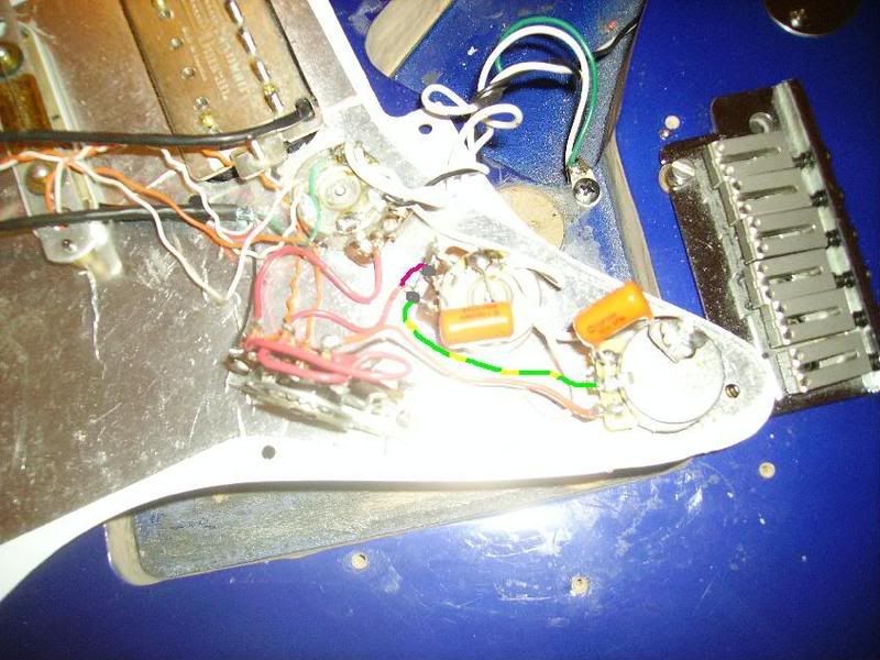 That's about all I can make out from the angle of the pictures (which are good, by the way). Sorry about that. Hopefully that helps somehow, or gives someone else something so they can come up with more for you. |
|
|
|
Post by sumgai on Jun 18, 2008 20:04:23 GMT -5
re,
Sorry, but I can't tell from your images whether or not your wiring matches the SD diagram. So before I accuse you of anything, could ask you to please take a shot at a different angle, say perhaps a 45° from straight down, and almost perpendcular to the wafer. Two would be even better, one from each side of said wafer. What I'm really after is the connections for those jumpers, and that's just not very clear.
Please? ;D
Thanks,
sumgai
|
|
reawx1
Rookie Solder Flinger
Posts: 4
Likes: 0
|
Post by reawx1 on Jun 19, 2008 14:53:09 GMT -5
Sorry about my crappy camera! gregarney.com/stuff/pict0155.JPGgregarney.com/stuff/pict0156.JPGSecond pic is upside-down. Umm, it is wired like this: 1 | 5 2 | 6 3 | 7 4 | 8 1. black wire from humbucker. 2. red wire from middle pickup 3. red wire from neck pickup 4. jumped to 5 5. red wire from left-most lug on volume pot 6. jumped to 7 7. red wire to tone pot 2 (for middle/bridge) 8. red wire to tone pot 1 (for neck) this assumes you're looking at it top-down (and upside down, of course), where the neck pickup is on top . Hope that helps! |
|
|
|
Post by sumgai on Jun 19, 2008 22:58:58 GMT -5
re, OK, I can see them all now, thanks. About the only thing that makes me even slightly suspicious is the soldering. On both tone controls, the cap leads going to the pot shells look like they might be cold, but out-of-focus like this, it's pretty hard to tell for sure.  Still and all, that's easy to check - just re-heat the joints until the solder flows evenly all around, then re-test.  For most guitars like this, a good all-around cap value is 0.022µfd. And yes, there is no way to keep the controls from interacting when you have the Neck selected along with either one of the other two pickups........ sorry, that's just the nature of the beast. HTH sumgai |
|