|
|
Post by D2o on Oct 11, 2008 7:48:27 GMT -5
Its interesting to see what continuity you get through the joins. I reckon a few Ohms is probably OK, say if everywhere on the foil is connected to everywhere else with less than say 100 Ohms (my guess). Where do you get the foil tape? cheers John I think that I recall ChrisK more or less seconding your guess recently - possibly even allowing a little more of a margin. By the way, I just use use hardware store aluminum duct tape ... funny thing is I think it's cheaper from Jaycar! (even factoring in conversion) Maybe I'll make a special trip for some tape  D2o |
|
|
|
Post by ozboomer on Oct 17, 2008 21:19:40 GMT -5
1:04 pm MEL time, 18/10/2008 I'm resuming the guitar project after a small hiatus... and have come up against an issue of sorts. Have another look at the inside of the guitar:  Note that there are 'inner cavities' that are like 'holes within holes'. Now, I can try to cover the holes but that doesn't seem to work well (see the upper metal tape covering the hole)... and I don't think I want to fill the hole with filler, 'coz it will prevent me from later installing certain types of pickups... I think. I don't want to use modelling clay or putty 'coz that will dry up and fall out. I guess that means I have to line the 'inner cavities' as well/separately. Have you seen these before... and what have YOU done about them when applying shielding? |
|
|
|
Post by ozboomer on Oct 18, 2008 3:25:24 GMT -5
7:07 pm MEL time, 18/10/2008 Well, THAT was a waste of an afternoon... No matter what I tried with this method, I couldn't get the continuity to work between the 'cup' and the 'walls' of the small cavity. Here's some details:  After an hour or more of fiddly work... I had continuity sort-of between all these strips... but not totally. 'No big deal' I thought, as I expected the vertical walls of the 'cup' would make a good connection with the strips. Here's the 'cup':  Anyway, I tried to get the 'cup' in hard against the strips, up against the wall of the cavity... but even using some sort of adhesive tape (or even smearing a surface layer of glue across the edge of the 'cup' and onto the vertical strips) to 'fix' the 'cup' to the strips didn't guarantee a good connection (from the top surface of the strips against the 'outer' surface of the 'cup').. even so, when there was some sort of continuity, the ohms reading was over 1200 ohms, so I guess the thing wouldn't work too well anyway. So after all this, I gave up and will try again another time, after I try and think about yet another way to do it...  Silly shielding  ... |
|
|
|
Post by newey on Oct 18, 2008 21:15:30 GMT -5
Given those added complexities in your particular cavity, conductive paint may be an easier option. More costly, but reducing one's personal grief is worth something.
Alternatively, copper tape with conductive glue would also probably work better- but again, more costly.
|
|
|
|
Post by D2o on Oct 18, 2008 21:23:18 GMT -5
Hi Oz,
Yes, I've seen them and yes I've shielded them too.
I was trying to upload some illustrated instructions I made for you on how to do it, but Photobucket is giving me trouble.
I was also going to tell you that if you don't need the little cavities shielded, don't bother until you do - just lay your tape down over them as if they weren't even there.
D2o
|
|
|
|
Post by ozboomer on Oct 19, 2008 2:46:51 GMT -5
6:39 pm MEL time, 19/10/2008
Well, I've done a little experimenting this afternoon... and provided I can keep the aluminium foil from tearing significantly, I think it'll work pretty well. With some 'non-glued' placement of foil, I could get continuity from one end of the cavity to the other with 0 ohms resistance.
Might give this method a try next(!)..
|
|
|
|
Post by ozboomer on Oct 24, 2008 23:02:21 GMT -5
2:51 pm MEL time, 25/10/2008 Have just finished lining-out the neck pickup cavity with aluminium foil, using a little contact adhesive across all the foil, viz:  There might be a few nicks and such but there is continuity through all of the lined area with zero resistance reading on my meter, so I think this will do. If nothing else, I'm getting jack of applying foil, finding the thing is too 'resistive', pulling it apart.. and repeating using a different technique, so this will just have t'do. I can certainly see why the techs I asked about doing this wouldn't touch the job with a 40-foot barge pole... |
|
|
|
Post by ozboomer on Oct 25, 2008 0:16:07 GMT -5
4:05 pm MEL time, 25/10/2008 Another hour, another section lined with foil, viz:  Discovered a problem with the previous lining - the foil just extends past the line of the pickguard; should've thought of that before.. Rats. So now I have a small, grubby, gluey mess on a few millimetres around the neck pup cavity. Oh well. One more section to do.. but not today - I've had enough of this for now. Maybe I'll have another go tomorrow.. |
|
|
|
Post by ozboomer on Oct 30, 2008 19:50:47 GMT -5
11:44 am MEL time, 31/10/2008 Have now completed the placement of the foil so as to line the cavity, viz: 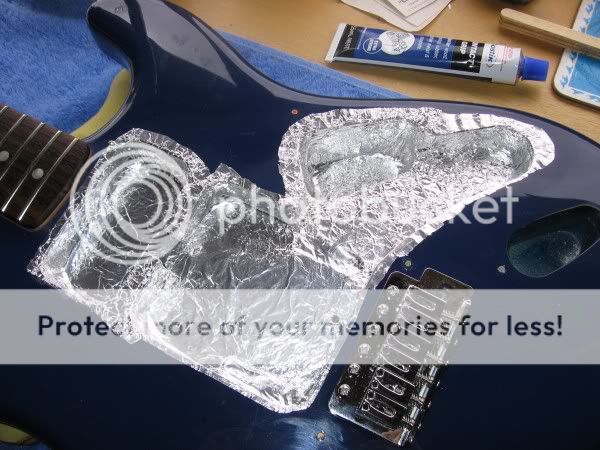 Putting a meter across various points over the foil shows I have continuity everywhere (it appears) and I don't see any more resistance than 1 or 2 ohms at the extremes. *Joy* Now to start the wiring. I intend to use an old pickguard I found upon which I'll mount all the components, so that my wire lengths, etc will be right... and I'll even be able to pop the finished wiring loom directly in the guitar for a trial, before I place the finished arrangement on the foil-backed pickguard. Getting a bit closer now ;D |
|
|
|
Post by ozboomer on Nov 1, 2008 7:11:23 GMT -5
10:11 am MEL time, 1/11/2008 Having had a bit of a think about things, I decided today to go with "Plan B", being to re-fit the standard wiring pickguard and just see what sort of difference the shielding has made. 11:32 am MEL time, 1/11/2008 Opening up the back panel, I just found it weird that there's a hole in there; you can even see where the tremolo mounting screws are coming through(!), viz:  12:12 pm MEL time, 1/11/2008 Ok, so I'm about to put everything together. Here are some photos:   Note that I have a wire with a washer coming from the circuit to 'ground' (the screw in the bottom of the cavity) and another wire with washer from the 'claw' underneath. 12:49 pm 1/11/2008 Ahhh, it works  (well, you'd expect so, given the wiring hasn't changed!) I have to get the intonation right and other things but I'm not doing a full set-up on it for now, as I'll probably pull it all apart tomorrow to start working on my circuit ...but it sounds like the shielding is doing something. Note that I haven't used the new pickguard, so there is no shielding for the front of the guitar as yet... but have a listen to the ambient noise (0.6 MB) that exists at the moment... and also some simple chords (1.31 MB). 11:04 pm 1/11/2008 Heh... I've been playing/practicing with the bullet tonight.. and it sounds pretty good to me Still, the blending, etc is the REAL reason for the mod, so I'm hoping to get onto that tomorrow. Good luck to me |
|
|
|
Post by newey on Nov 1, 2008 7:47:57 GMT -5
You won't get anywhere near the full benefit of the shielding without doing the pickguard. Since you already did the cavity and attached the wire, it would be easy enough to put some foil on the underside of your old guard. Or, just move on to the new one . . . |
|
|
|
Post by ozboomer on Nov 6, 2008 22:37:44 GMT -5
2:22 pm MEL time, 7/11/2008 I've taken the strings off and removed the pickguard and electronics and I've made an interesting discovery... These pickups appear to actually be wax potted, viz:  I guess this would explain something of how the guitar was originally relatively quiet? ...but this means I won't be changing the pickup covers this time around - I'm sure not going to try and take the covers off when the pickups are basically stuck inside 'em. So the 'Reverse Tux' look I was going for will have to wait until I get some new pickups. Pooh  A question though... Have a look at the way the pickups have been wired to the 5-way switch:  (the 'crimping' is from some heatsinks I used when de-soldering the pickups) We're looking at bridge - middle - neck pickup leads, left-to-right. Now, when the pickups were wired into the circuit, the coloured leads you see here were connected to the 5-way switch and the braided shields were all twisted together and soldered onto the shell of a pot, hence grounded. What do you think the other wire might be for? I'm guessing it's something to do with the 'other end' of the pot winding.. but I don't know that. Remember, this is a Chinese-made, 'cheapo' Squier Bullet Strat from a couple of years ago, so I doubt the other lead would be a centre-tap or something(!) Anyway, if someone would just confirm, please, that I should replicate the original wiring in my new circuit; that is, the coloured wire is 'hot' (signal) and to use the braided shielding as the ground connection... and just leave that other coloured wire 'float'. Once I get some clues about this, I'll start on the re-wiring in ernest. |
|
|
|
Post by newey on Nov 6, 2008 22:57:46 GMT -5
You have a 3-wire SC, the unused wire is the signal return, and the braided wire is the shield. Both those should be grounded. I can't tell from your photos whether they may be grounded to the shields right at the ends there.
Leaving them "as is" runs the risk that they may be a contributor to noise. If you are going to undertake any G-Nutz wiring, they may need to go elsewhere than straight to ground, meaning you'll then have to extend those wires anyway.
Also:
I see some waxy stuff inside the cover, and I see the baseplate, where's the coil?
|
|
|
|
Post by ozboomer on Nov 7, 2008 0:31:52 GMT -5
You have a 3-wire SC, the unused wire is the signal return, and the braided wire is the shield. Both those should be grounded. I can't tell from your photos whether they may be grounded to the shields right at the ends there. 'SC'? The ends of the 'second wire' are simply cut off (see the 'red' wire inside the bridge(white) lead to the left). I can be fairly certain they would not have been twisted into the shields, before they were originally soldered to the pot shell. Leaving them "as is" runs the risk that they may be a contributor to noise. Ok... So, again, referring to that left-most lead in the photo... If I strip-back the 'red' lead ('signal return') and twist that into the braided shield for that lead... and then wire the shield to a ground point, I should be Ok? As it is, I'm not doing the 'Rolls Royce' shielding treatment here, so the pickups only need to have a 'ground' and a 'hot', as I understand (see the original design); so I expect what I described above should be Ok..? I see some waxy stuff inside the cover, and I see the baseplate, where's the coil? As near as I can tell, the coil is buried inside that 'waxy stuff'; it fills the pickup cover to within 1/8"(3 mm) of the bottom of the pickup cover. I think the pickup cover is acting as a container and whatever's inside it is going to be a pain to take out (I think), viz:  Thanks for your thoughts... |
|
|
|
Post by ozboomer on Nov 7, 2008 1:01:55 GMT -5
...and I thought I'd just show a layout of all the electronics that has yet to be connected:  I also managed to maintain some of the connections to the 5-way switch, so anything that makes life easier I also worked-out how the 5-way works, somewhat:  The wiring begins... |
|
|
|
Post by andy on Nov 7, 2008 5:44:59 GMT -5
 How peculiar! It may just be the angle of the photo, but it looks as though the coil is extremely shallow- normally it would be wound around a bobbin, and be almost as deep at the cover itself. While low output is not neccessarily a bad thing, those pickups may be very low. I think it is safe to say that the coil is wax potted, although that only serves to stop the coil being able to vibrate in its position, holding off that high pitched squeal one can get at very high voulme.
|
|
|
|
Post by newey on Nov 7, 2008 6:03:07 GMT -5
"SC" means a single coil pickup, as opposed to a humbucker or "HB". Sorry for the shorthand, we use that a lot around here. I don't know what you've got there but it doesn't look like any Strat pickup I've ever seen, potted or otherwise. I can see your blue carpeting through the hole in the cover! Are there metal pole pieces protruding through the holes in the cover? Have you put a meter on these pickups (and on this one in particular) to ascertain that there is output? Are there wires protruding from the "waxy stuff"? When you say that the guitar was previously "relatively quiet", were you getting output from all 3 pickups (the screwdriver "tap test"?) Between the wiring and this pickup, you are apparently dealing with a guitar that has been heavily modified. No factory, Chinese or otherwise, would "wax pot" a Strat pickup- and what you have doesn't look like a Std Strat pickup anyway. As far as the wiring is concerned, you would want to run a separate wire for the signal return if the goal is to test for noise reduction- but that statement presupposes ordinary Strat "SC" pickups are in use, which doesn't appear to be true here. Count me thoroughly puzzled. |
|
|
|
Post by ozboomer on Nov 7, 2008 7:09:56 GMT -5
Heh... These crazy pickups are certainly causing some confusion, eh? 'tis exactly what I thought when I first pulled 'em off the original pickguard today. I don't know what you've got there but it doesn't look like any Strat pickup I've ever seen, potted or otherwise. I can see your blue carpeting through the hole in the cover! Are there metal pole pieces protruding through the holes in the cover? Ya, everything 'externally' looks sensible. These are the pickups that were installed 'stock' in the Bullet when I bought it (new) in late 2006 or so. Have a look at some of the earlier photos in this thread and you'll see the pickups look 'normal' from the outside... and all the sound files I've posted into this thread have been created by using this guitar with these weirdo pickups, including the simple chords, etc from my 1st November posting, where I played some chords with the original pickguard (and these pickups) re-installed after I did the cavity shielding... and you can hear the different pickups give different sounds. If it helps, here's another photo I took just now:  Note that if I push on the poles from the top, nothing comes out of the pickup cover. Also, the poles themselves are strongly magnetized and attract a screwdriver strongly... but the baseplate is only weakly magnetic, whether it is isolated from the pickup cover OR if it's attached. Have you put a meter on these pickups (and on this one in particular) to ascertain that there is output? Well, ALL the pickups are like this... and I measured the pickups again just now and they all have a resistance value of ~8k6... ...and yes, all of the pickups were producing output.. the 'tap test' confirms it as does the sound differences we hear, as mentioned above. Between the wiring and this pickup, you are apparently dealing with a guitar that has been heavily modified. No factory, Chinese or otherwise, would "wax pot" a Strat pickup- and what you have doesn't look like a Std Strat pickup anyway. Well, that's what I'm wondering about. I bought the guitar 'off the shelf' at a local well-known music shop here in Melbourne... but I always wondered about it.. 'coz, for example, it had a tremolo bridge installed and I thought Bullets back in 2006 were always hardtails? (trem. versions are available this year in Bullets, I think) As far as the wiring is concerned, you would want to run a separate wire for the signal return if the goal is to test for noise reduction- ...from where to where? As the circuit shows (as do most of the circuits I've seen), there's no indication of a 'second wire' from the pickups, except for the ground connection...? 'tis a puzzlement... |
|
|
|
Post by D2o on Nov 7, 2008 9:36:15 GMT -5
If this is actual wax, is there any reason you cannot "un"pot them? (i.e. apply some heat to melt the existing wax - possibly by actual potting them in hot wax again) My thought is that once the wax is soft, you may be able to safely remove the cover to see what's going on. I'm not saying ... I'm asking. D2o |
|
|
|
Post by ozboomer on Nov 7, 2008 10:22:23 GMT -5
If this is actual wax, is there any reason you cannot "un"pot them? (i.e. apply some heat to melt the existing wax - possibly by actual potting them in hot wax again) That's certainly feasible.. but not for me(!). Remember, I'm not too confident with fiddling about with these... 'more advanced'... techniques, and in some ways, I'm thinking like 'if it's not broken, don't fix it'. All I want to do with the project is to make the 'blender' and 'parallel/serial' changes ... and I'm quite Ok with leaving the 'black box' of these funny pickups alone... It all comes back to knowing what to do with the 'signal return' wire, as it was floating there in the original wiring.. I 'spose I'm just trying to keep focused or sumfin'... and not let the scope of what the project is about get too far off the track... |
|
|
|
Post by D2o on Nov 7, 2008 10:43:56 GMT -5
Oz, I hear you. I've bitten off more than I intended to chew on occasion. I believe that I benefited from it, but I acknowledge that it can consume more time and money than originally planned. By the way, I am on a first name basis with Mr. Murphy. D2o |
|
|
|
Post by newey on Nov 7, 2008 12:38:29 GMT -5
Many Strat pickups do not have a separate shield, and thus show only signal out and signal return. Where there is a braided shield, it will always go to ground, this is assumed in many diagrams.
Whether the signal return goes to ground or not depends on your wiring scheme. To wire series/parallel and/or a blender, these won't be going directly to ground, so you might as well extend the wires now if you're planning to use the same pickups, whatever they are.
Andy's right, if there's a coil in there it must be a darn small one. Since they work, there's obviously something in there, but I'm not seeing it.
IMHO, I would not want to spend a lot of time rewiring with those pickups, I'd be looking to upgrade them as long as I was doing the other work anyway. Cheap Strat replacement pups can be had for about $12-$15@ (USD). While one could spend much more for really good ones, even the cheapies might be an improvement over what you've got there.
|
|
|
|
Post by ozboomer on Nov 11, 2008 5:46:35 GMT -5
I was chatting with one of my guitar repair guru mates last night and he gave me some more info about these weirdo pickups... * It's fairly common to see this treatment of pickups on the Bullet Strats. The pickup cover does work like a container and the coil rests inside the pickup cover and is then covered in wax or epoxy; as already explained, this treatment helps to deal with the 'screech' that sometimes happens when the pickup cover resonates at high volumes; * The two wires (we've been calling 'signal' and 'return') are purely used for phase/reverse winding -styles of wiring. In this case, we have: Neck ----> white --> SIGNAL
Middle --> red ----> SIGNAL
Bridge --> white --> SIGNAL
This is how we get the noise cancelling happening currently in positions 2 and 4: the classic reverse-wound humbucking thing. So, I should probably maintain that arrangement in my wiring scheme. * As mentioned before, the unused wire should mesh-in with the shield and be taken to ground. So, it might all look weird but there's not really anything THAT unusual with the pickups. The general consensus last night was to leave these pickups alone (they're not worth the trouble to 'unwax' them and put 'em back together when there's nothing wrong with them)... and to see how the guitar sounds after the wiring mod... the ol' ScientificMethod(tm) y'know... Again, they're running around 8+ kohms, so they should have a decent output... and I might swap-in some 'better' pickups at a later time. Layout and wiring: here I come... |
|
|
|
Post by D2o on Nov 11, 2008 9:50:41 GMT -5
Layout and wiring: here I come... Go to it! Thanks for the update, sounds like you're working it out.  D2o |
|
|
|
Post by ozboomer on Nov 14, 2008 23:34:41 GMT -5
3:23 pm MEL time, 15/11/2008 I started assembling the electronic components on the old pickguard today so I can wire things up using short wires where possible. Note the DPDT switch between the volume/tone controls and the 5-way switch -- that's probably going to be fun to get my soldering iron around, I expect... ...and even though the currents around here are small, I still wonder if there would be any problem with how close the volume control is to the bridge pickup (they're only a couple of millimetres apart)... It might be different on the final pickguard.. but should I take any precautions about them being so close? Here's a photo:  Thanks for the continuing interest and suggestions, folks... |
|
|
|
Post by ashcatlt on Nov 15, 2008 1:08:39 GMT -5
Single Coil Sure they were, viz:  It's a little blurry. If'n you had a higher resolution version of this shot we could get some happier zooming going on. I'm pretty sure, though, that I see the white wire from the mid pickup poking out and mixing in with the shield wires.
|
|
|
|
Post by ozboomer on Jan 5, 2009 5:31:40 GMT -5
8:48 pm 5/01/2009, MEL time... Well, here we are, about 7 weeks since I started trying to get this thing to work... and I've taken some photos of the latest incarnation, viz:      Now, in short, it doesn't work  I guessed I might be biting off more than I could chew(!) with this project... but let's have a look... I wired it all into the guitar body (covering all the exposed joins with insulating tape, of course), connected the jack wires (x2) and the bridge/ground wire to one of the pot shells, re-strung, re-tuned (more-or-less) and plugged in ANOTHER guitar into the amp, and everything was Ok. BUT! When I plugged-in the guitar with this mod, all I heard was humming, lots of noise and some random arrangement of the 5-way/toggle/pots produced a little bit of tone but nothing to really speak of. The thing basically didn't work. If you look along with the schematic and wiring layout and follow along... I took the thing out of the guitar tonight, and attacked it with my digital meter (ohm scale). I checked the potential/continuity around the circuit and everything seems fine (although I've installed the DPDT upside-down, so when the toggle is pointing DOWN, I'm actually running the "parallel" arrangement - big deal). For example, I can place a meter probe on a pot shell and all the "green" lines show continuity and the "red" lines show no-connection. Oh... One thing to note (as I couldn't make up my mind how we decided it should run)... The 'return' wire from the pickups is left floating, as I thought that was the way it was originally done on each of the pickups... but given things aren't working at all, maybe I'm wrong? ... viz:  However... one of the things that seems to be a problem is the pots. They don't track at all properly, with the 500k pots showing something like: 0.. 2.. 10.. 23.. 100.. infinite... and the "blender" 100k pot can be sitting at-rest, fully clockwise, for example, and the meter will flip between 0.. 2.3k.. 35k.. 4.5k... 0.2k... and so on when using alligator clips between the probes and the pot terminals, keeping everything motionless. Another thing... When looking at the blender pot, if I have the toggle in either position, I will generally have some continuity between the baseplate of any pickup and the shell of the blender pot. The shell of that pot is not "used" in any part of the circuit (that is, it's not tied to ground or anything) and yet it's till grounded somehow. One thing I was going to try... was to short the terminals of the blender pot; I mean, join wiper and one of the other terminals... just to see if I could isolate/remove the variability of THAT pot. Anyway, before I chuck the silly thing away, is there anything else I can do/try to see where things might be going awry? The fact that all the wiring seems to be connected Ok seems promising but how do I tie-down why there's no sound from the thing!? Thanks in anticipation... |
|
|
|
Post by newey on Jan 5, 2009 7:17:17 GMT -5
Oz-
Welcome back!
This would be where I would first direct my attention. If the green wires are, in fact, the shield (not clear to me), and the wires left hanging are the signal returns, then those need to be wired in as shown on your diagram.
|
|
|
|
Post by ozboomer on Jan 5, 2009 7:39:16 GMT -5
This would be where I would first direct my attention. If the green wires are, in fact, the shield (not clear to me), and the wires left hanging are the signal returns, then those need to be wired in as shown on your diagram. Hmm.. in the photo of the pickup wires, the green wires are from the shielding of the pickup cables... they currently go 'into the circuit'... but the more I re-read this thread, I think what should be happening is the shielding from the pickups might (should?) be grounded and it's these 'return' wires that should go into the circuit. Not a real big deal to fix in the wiring, I think... but a fairly fundamental difference in what I understood the circuit was doing. I plan to have another go come this weekend... so we'll see, eh? |
|
|
|
Post by JohnH on Jan 5, 2009 14:56:18 GMT -5
I think Newey is right and the first thing to do is to check the function of the three wires from each pup. I would have guessed that red and white (or maybe red and green) are the ends of the coil and need to be both into the circuit, and the green (or white) is connceted to the pup base and should be grounded, but only for reasons of shielding, not of the sound signal.
If you disconnect a pup fully, you should then be able to measure several k (say 5k to 7k - depending on the pups) between the coil wires, and infinite resistance from each of them to the baseplate wire, and hence check the function of each colour. Ive never seen a red wire that wasnt something important though!
John
|
|


 ...
...

 (well, you'd expect so, given the wiring hasn't changed!) I have to get the intonation right and other things but I'm not doing a full set-up on it for now, as I'll probably pull it all apart tomorrow to start working on my circuit

 How peculiar! It may just be the angle of the photo, but it looks as though the coil is extremely shallow- normally it would be wound around a bobbin, and be almost as deep at the cover itself. While low output is not neccessarily a bad thing, those pickups may be very low.


 I guessed I might be biting off more than I could chew(!) with this project... but let's have a look...