I was having PM conversations with ChrisK about my understandings of these things, but then i decided it might be better to post to get some other inputs. -Please.

===============================
In the last post, ChrisK pointed me towards a discussion about a Gibson L-6S, and the varitone circuit. Within the thread, more insight to inductors, what they do, and Bill Lawrence's "Q" filter.
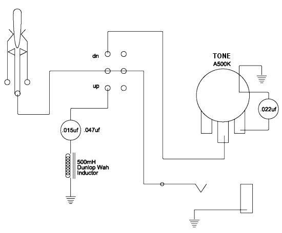
Durring the past week or so, ive been experimenting with my little "Mid-Boost" circuit, using an inductor from a Crybaby Wah (500mH). Im simply taking a parallel feed off the "hot" to a switch. With the switch engaged, it has a cap in series with an inductor, to ground. Ive been swapping out caps until i hear it "do something". -obviously, there must be a more scientific way of doing this.
But more than that, i still feel that i just dont know what im shooting for, or where to aim.
-Heres what i mean. -i read this in the aforementioned L-6S thread. -posted by Sumgai, it was in referance to someone else guessing what the inductor value was for the L-6S tone circuit. they guessed 900mH.
In my circuit, using a 500mH inductor from a Crybaby wah, and with the help of an online LCR calculator, i have stacked several caps in parallel to get a value of .008uf. This puts the center frequency right around 2.5k. According to Sumgai, thats way too high. It should be around 167hz. In that case, i need a cap value of 1.8uf. And ill admit, all my circuit seems to do is roll off the highs a tad. Maybe a slight mid boost, but nothing all that dramatic.
ive got 3 questions:
1) what center frequency really IS a good place to start?
2) i still dont know if this tone circuit is a NOTCH, (as in a scoop, or dip) -or a BOOST.
3) other than make the cap value a little more readily available, what else does a higher value inductor do for the circuit? does it have anything to do with the "Q" or how narrow (or wide) the bandwidth is around the center frequency?
I hope ypou can help. Ive been wracking my brain on this, and i feel like im on the right track, but still in the dark. I know just enough to be dangerous.
===================================================================================
ChrisK posted back:
en.wikipedia.org/wiki/RLC_circuit(If you look at the series RLC circuit figure, you'll see the pickup model that we use.)
At the bottom of the article there are some good links.
www.phy.hk/wiki/englishhtm/RLC.htm======================================================================================
Im still groping in the dark, but i think i feel something...
I was looking at the java applet ChrisK linked me too, and i think ive figgured out a few basics. Correct me if im wrong:
The higher the henry value of the inductor, the more narrow the bell curve.
The higher the resistance, the lower the amplitude of the resonant frequency.
And the value of the cap decides where on the bell curve your chosen resonant frequency actually is.
It aslo has a direct bearing on what the resonant frequency actually.
But an inductor is also a High-Pass filter isnt it? if your Cap value is low, more highs roll off. I your cap value is too high -say, 2uf, youll be below the high pass cut off point, and the lower the overall output is. Its like taking windings off the pickup. So... how do i know where the cut off point of the inductor is?
The applet must be for household electrical circuits or something... I cant plug in the values im using. But i noticed that if i lower the inductor all the way down (to 10mH) the bell curve gets very wide. Ive seen Varitone inductor values from 1.5h to 7.2h, which "should" be very tight and focused. And of course, were talking about much higher frequencies than what this applet shows, and much lower caps. Im also guessing that the resistance shown in the applet, would be the ohm reading from the pickups, in my scenario. My bridge pup is over 14k (and older Bill Lawrence L90) so that will lower the amplitude of the resonant frequency. -right? And again, i cant plug in a value that high. -bummer.
yes, i know there are mathematical formulas for all this, but i failed 9th grade math 3 years straight. I REALLY just dont get it.
In one of the threads ChrisK linked me too, Wolf said if you take the transformer out of an old dial up modem, its rated at about 1.4H. I happened to have an old dial up modem, so i tried it. I "think" im in the same ballpark as the sounds im getting with my Torres Varitone (in a different guitar.) Ive got a .0047uf cap, and the resonant frequency is right around 1900Hz. -But again... (heres me guessing) that if i go with a higher value inductor, -say the 7.2, ill get an even tighter bell curve. A more pronounced effect. I not going to get any more gain. Its set by the pickups. but the tighter the bell curve, the more percieved "effect", so in a sense, -more gain. more particular attention to that specific frequency. Ill have to revalue the cap (900pf or so) to hit the same frequency.
In my local electronics surplus store, they have some small transformers. Theyre all rated at certain voltages. step down transformers, from 120vac to 10vac. (for instance) -Most just have a part number, or maybe some fine print on a small label. Is there a way to determine its "Henry" rating by looking at the numbers? Or with an ohm meter? The inductor from the modem reads 48 ohms, If that tells you anything. -I dont think it does...
For what its worth, im getting more of the desired effect just by having a .015uf cap on my regular tone pot. Im really looking for an obvious, over the top, mid-peak/boost. Passive.


 cap in one switch, and a .047uf on the other. Both just sounded muddy, almost like a regular tone roll-off. However, with both caps engaged, and in parallel to eachother, feeding the inductor together (to ground) I got a much more obvious effect of a huge Mid-Scoop. Sort of like an accoustic guitar piezo pickup. And the overall output dropped quite a bit. -Which makes sence, since i just sucked all the 'tone" out of it.