|
|
Post by jewellworks on Feb 24, 2009 23:13:18 GMT -5
Since I was unable to get the results I was looking for in my last thread, I decided to try a different approach.  Ive got a 2 HB guitar. 2 vol/ 2 tone. (A500k's all) In the neck Ive got a Gibson 490R, 2 wire. In the bridge Ive got a Bill Lawrence L90, 2 wire. the 490 reads 7.8k. the L90 reads 14.8k. I need ideas. a Master volume? A Master tone? Leaving the other pots to do something else? Like what?? I tried separate bass cut/treble cut pots. That was cool. But what else can I do? Plus, the tone pots are both DPDT push/pull switches. Those are empty and unused right now. I tried reversing the phase, but I never really liked the sound of phase reversal. If it were more even across all the strings, that might be an option, but the tone from string to string is too erratic. Ive seen reference to a "1/2 phase reversal cap" elsewhere in this forum, but I haven't found the actual diagram anywhere. Id really like to hear what that sounds like... I know I'm limited to what I can do with both pickups being 2 wire. I'm open to ideas. -Even a total rewire. I love the sound of it wired "normal", but I'd kinda like something to do with those push pulls, if theres anything useful to be done with them. Thanx |
|
|
|
Post by cynical1 on Feb 25, 2009 0:36:47 GMT -5
I would highly recommend the Free Woman Tone mod from ChrisK. Happy Trails Cynical One |
|
|
|
Post by ChrisK on Feb 25, 2009 12:33:58 GMT -5
If the structure was parallel out of phase, then yes, it's a very thin sound. Series out of phase is much more interesting. Out of phase is going to be specific to certain areas of frequency. In essence, in parallel OOP, one is averaging the harmonic content (including the fundamental) between two generators, one of which is out of phase to the other. In series OOP one is adding ( subtracting) the harmonic content (including the fundamental) between two generators, one of which is out of phase to the other. This is where, in parallel OOP, the phase reversed pickup is capacitively coupled to the other pickup. I've typically seen it done on the neck pickup. In essence, the neck pickup is phase reversed, and the lead going to the selector switch goes thru a series cap, which is a high pass filter. I've seen values on the order of .01 to .02 uF used. If you look at the Baja Tele wiring, it's the 0.01 uF disc ceramic (bleah! ceramic  ) cap. www.fender.com/support/diagrams/pdf_temp1/telecaster/0141502A/SD0141502APg2.pdfwww.fender.com/support/diagrams/pdf_temp1/telecaster/0141502A/SD0141502APg4.pdfIf you wonder how the S-1 switch works.... look hereWhen you say 2-wire, do you mean a single conductor plus shield, or 2 wires plus shield? |
|
|
|
Post by jewellworks on Feb 25, 2009 21:34:03 GMT -5
Parallel OOP is simply reversing the leads on one pickup, correct? thats what i did, (and normally do) and i never like it. Series out of phase would be wiring the + of one pickup to the + of the other, and then one of the - leads would go to the switch.  Im trying to picture what series out of phase is... so I would have to switch from parallel to series, AND reverse the lead going to the switch... hhhmmm -sounds like I need a 3PDT for the series phase. And you wonder why im confused? adding (subtracting) Now THIS makes sence to me, because your limiting what frequencies are out of phase, and leaving the rest "intact". It looks like I need a 3PDT switch for the series phase, and a DPDT for the 1/2 phase. Do they even make a A500k pot, with a 3PDT push/pull? That way, it'd look stock.  BTW, 2 wire = 1 conductor and shield -actually, the BL L90 is a 3 wire. 2 wires plus a shield. But Im pretty sure the shield is just a "body ground". I solder it and the black to ground together. I dont think its a tap, otherwise, Id have one coil shunted to ground, and thats not whats happining. Theyre both on full and raging! ;D |
|
|
|
Post by newey on Feb 25, 2009 22:20:20 GMT -5
You have some options with this one. The Gibby pup, with one wire and a shield, pretty much just wire it up and listen to it work. That's about all you can do.
A while ago, we had some discussion about three wire (2 + shield) HBs and what could be done with them, but it was in the middle of another topic and I can't seem to find it at the moment.
You have 2 DPDT pots, so you don't need a push/pull 4PDT pot, which AFAIK doesn't exist anyway. Unless you are inclined to take the Gibby HB apart and make some added connections, you can't really do anything with that one. The question really comes down to what you can do with the BL pup and 2 dpdt switches. One of those could be used for the "woman tone" suggestion by simply bringing a cap in/out of the circuit. The other could be to put the BL OOP with the Gibby pup, but that would be parallel OOP (I think) which you don't really want.
That's all I have at the moment. I'll think on it some.
|
|
|
|
Post by ChrisK on Feb 26, 2009 17:12:56 GMT -5
Yes, and wiring it in parallel with the other pickup(s). It's exactly what you just said.  Sorry, implicit inference as in adding a negative is in actuality subtracting. Nope. Parallel to parallel half OOP takes only a DPDT (and semi-secret ChrisK knowledge). Parallel to series takes a DPDT also. However combining both depends on the structure of the rest of the circuit. But, having pickups with a single conductor with shield makes series, series OOP, and parallel OOP somewhat problematic in that the pickup cover and shield is connected to the signal output. You can play a guitar wired this way, but just don't touch the pickup covers. |
|
|
|
Post by jewellworks on Feb 26, 2009 20:53:39 GMT -5
To test what this sounds like, I just wired everything straight, no switches. Series oop. I likes it. Much more interesting indeed. Thinner, but not nasaly, and a more even response across all strings. The down-side: lower output. But i can live with it. Parallel oop, with the 1/2 phase .01uf cap. I likes it too! I likes em both!! yippie! ;D Now if ChrisK could only reveal the secret password to unlock the secrets of how to do it using a single DPDT each, Id be in bidness... I could close up the back of my guitar, and rejoin my wife in the other room after a month's absence... until my next project that is... |
|
|
|
Post by jewellworks on Feb 27, 2009 21:53:43 GMT -5
Heres what I came up with. The half plase is on the neck pup, the series phase is on the bridge. I think this'll work... WhatIim not sure about is what will happen with the different switch positions, but i think Im right...  |
|
|
|
Post by ChrisK on Feb 27, 2009 23:53:38 GMT -5
I see that you figured out how to do the normal parallel phase/half OOP parallel phase.  Unfortunately, this switch needs to be located in between the two wires from the pickup to the connections to the volume and tone pots, and not where you have it. As it is now, you are switching the phase of two connections while the ends of the neck tone and volume pots remain grounded. Likewise, the same permanent connection remains for the bridge series phase switch from its volume and tone pots. I'm not quite sure what this switch is actually supposed to do. |
|
|
|
Post by jewellworks on Feb 28, 2009 19:17:41 GMT -5
hows this? mo better? 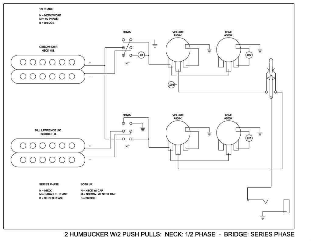 Im also concerned about Popping when switching. I know ill have to add some 10M resistors, but im not sure where, or how many. Why does it pop to begin with? |
|
|
|
Post by ChrisK on Feb 28, 2009 23:37:39 GMT -5
The popping occurs because the switched 0.01uF cap can be left with a charge (including zero) that is different than the instantaneous DC level of the AC circuit that it's switched into. For instance, if the instantaneous DC level of the AC signal was positive maximum when the cap was switched out, and the instantaneous DC level of the AC signal was negative maximum when the cap was switched back in, the signal would go instantaneously to the opposite DC level causing a "pop".
Since it is most likely that the instantaneous DC level of the AC signal WILL be different when the cap is switched back in, the pop will always occur at various degrees.
This is exacerbated in the Varitone circuit since there is an inductor (spark coil) at play.
Put a 10 Meg Ohm resistor in parallel with the 0.01uF series cap as this will dissipate the charge, IF you have a "pop" issue.
Otherwise, your design looks ok. There will be the traditional LP volume control interaction when either is turned most of the way down.
Wire it up and fire it up.
|
|


 ) cap.
 Im trying to picture what series out of phase is...


